


VT4888
Array Applications Manual
For models VT4889, VT4888, VT4887, VT4881, VT4880

TABLE OF CONTENTS
PAGE
GENERAL AMPLIFICATION NOTES & REQUIREMENTS…………………. 3
SUBWOOFER WIRING NOTES………………………………………………… 4
STANDARD AMPLIFICATION RACK
LIMITER SETTINGS NOTES …………….……………………………..…….. 5
VT4887 & VT4881
TRANSDUCER COMPLEMENT.………………………………….…….. 5
AMPLIFIER CONFIGURATION OPTIONS
VT4887 & VT4881 ARRAY WIRING……………………………………………. 7
VT4888
TRANSDUCER COMPLEMENT………………………………………… 8
AMPLIFIER CONFIGURATION OPTIONS
VT4888 ARRAY WIRING………………………………………………………... 10
VT4889
TRANSDUCER COMPLEMENT………………………………………… 11
AMPLIFIER CONFIGURATION OPTIONS
VT4880 TRANSDUCER COMPLEMENT & AMPLIFIER CONFIGURATION.. 12
VT4889 ARRAY WIRING ……………….…………………………………….. 13
VERTEC SYSTEMS SUSPENSION HARDWARE
AND ASSEMBLY NOTES………………………………………………… 14
PARTS GUIDE: VERTEC SYSTEMS SUSPENSION HARDWARE……………. 15
VERTEC VT4888, VT4887, VT4881: SYSTEM SUSPENSION FRAMES……… 16
VERTEC: SYSTEM SUSPENSION HINGE BARS………………………………. 17
PICTURE: VT4889 WITH VT4887 HANG UNDER USING VT4800-DA….…... 18
PICTURE: VT4887 CLUSTER SUSPENDED USING VT4887-AF……………… 19
VERTEC SUPPORT TEAM AND WEBLINKS…………………………….……. . 20
Page 2

GENERAL AMPLIFICATION NOTES & REQUIREMENTS
• For the purpose of this discussion: Crown MA series amplifiers are used below. HF
indicates High Frequency drivers, MF indicates Mid Frequency drivers, LF indicates
Low Frequency drivers and VLF stands for Very Low Frequency drivers (subwoofers).
• Equivalent amplifiers can be used as substitutions.
• Users should observe differences in input sensitivity and maximum available power at a
given impedance load.
• Users may choose to use the same size amplifier to power all components / passbands.
• DSP crossover presets provided by JBL assume that the same amplifier models with
equal voltage gain, are used for each bandpass.
• If different gain settings or amplifiers models are used, users may need to adjust the
output gains of the digital controller(s).
VT4889
• 4 VT4889 can be powered with (4) MA-3600, although the MA-5002 is recommended.
Two boxes are wired in parallel per NL8 circuit.
(HF: CH1 & CH2, MF: CH1 & CH2, LO1: CH1 & CH2, LO2: CH1 & CH2)
• Using MA-5002’s would provide enough power to drive up to 6 VT4889.
Three boxes are wired in parallel per NL8 circuit.
• MA-2402 or MA-3600 can be used for the HF section to power 2 or 3 boxes.
VT4888
• 4 VT4888 can be powered with (4) MA-3600, although the MA-5002 is recommended.
Two boxes are wired in parallel per NL8 circuit.
(HF: CH1 & CH2, MF: CH1 & CH2, LO1: CH1 & CH2, LO2: CH1 & CH2)
• Using MA-5002’s would provide enough power to drive up to 6 VT4888.
Three boxes are wired in parallel.
• MA-2402 or MA-3600 can be used for the HF section to power 2 or 3 boxes.
VT 4887
• 4 VT4887 can be powered with one (1) MA-5002.
If four boxes are wired in parallel per NL8 circuit then
CH1: LF @ 2 ohms & CH2: MH/HF @ 2 ohms.
• MA-2402 or MA-3600 or MA-36x12 can be used if 2 boxes are wired in parallel instead.
VT4880
• 2 VT4880 are usually wired to (1) MA-3600 or (1) MA-5002.
If two boxes are wired in parallel using NL4 cables then
CH1: 2258 left, pin 1+
• Up to 3 boxes could be wired in parallel with loads of 2.7 ohms per amp channel.
VT4881
• 2 VT4881 are usually wired to (1) MA-3600 or (1) MA-5002.
If two boxes are wired in parallel using NL8 cables then
CH1: 2256G coil 1, pin 1+
• Up to 3 boxes could be wired in parallel with loads of 2.7 ohms per amp channel.
• Make parallel connections at amplifier rack to minimize cable losses.
@ 4 ohms & CH2: 2258 right, pin 2+ @ 4 ohms.
@ 4 ohms & CH2: 2256G coil 2, pin 2+ @ 4 ohms.
Page 3

NOTES ON SUBWOOFER WIRING
• VT4880: Users may choose to wire both 2258 (18”) components in parallel to one (1)
channel of a MA-3600 or MA-5002 for (4) ohms load. In this case each amplifier
channel drives one VT4880. If two VT4880 are wired in parallel, the load is two ohms
and there will be no amplifier power headroom.
• VT4881: Users may choose to wire both coils
one (1)
channel drives one VT4881. If two VT4881 are wired in parallel, the load is two ohms.
USERS MUST NOT WIRE THE VOICE COILS ON A 2256G (VT4881) OUT OF
POLARITY TO EACH OTHER.
NL8: PIN 1 +
NL8: PIN 2 +
channel of a MA-3600 or MA-5002 for (4) ohms load. In this case each amplifier
= RED CONNECTOR A & BLACK CONNECTOR A
= RED CONNECTOR B & BLACK CONNECTOR B
in a single 2256G component in parallel to
STANDARD AMPLIFICATION RACK
For those users looking to minimize amplifier rack configurations, one rack with 4 MA-5002
and 2 NL8 output circuits can power up to:
• 4 to 6 VT4889 (2 or 3 boxes per circuits AMPS: HF, MF, LF1, LF2)
OR
• 4 to 6 VT4888 (2 or 3 boxes per circuits AMPS: HF, MF, LF1, LF2)
OR
• 8 VT4887 & 4 VT4881
(4 VT4887 & 2 VT4881 per circuit AMPS: MF/HF, LF, VLF1, VLF2)
This rack would use the same input signal path from the digital controller of choice. Users
would only need to recall the appropriate DSP file on the unit.
• VT4889 or VT4888
DSP outputs: LO, MID, HIGH (stereo)
• VT4887 & VT4881
DSP outputs: SUB, LO, MID/HIGH (stereo)
Page 4
NOTES REGARDING LIMITER SETTINGS
• The recommended limiter threshold settings provide 3 dB of headroom before the
component or bandpass peak voltage is reached.
• The component or bandpass peak voltage is 6 dB above the voltage used at
continuous maximum power.
• These settings assume the use of a Crown MA-5002 in stereo mode with input
sensitivity of 1.4V for a voltage gain of 37 dB. Amplifier limiter and Offset
Integration switches are set to the off
• If a different amplifier is used or if the input sensitivity is changed, the limiter
threshold must be re-calculated.
• Not all DSP controllers behave the same way. Please study your unit accordingly.
• Users must take into consideration that the digital controller gain outputs are not
all “0” dB, i.e. for VT4889/4880, the VLF is at +6 dB, the LF is at 0 dB, the MF is
at -2.5 dB and the HF is at - 4 dB. Hence, the actual headroom before limiter
threshold is effectively greater than it may seem from the above charts.
• Users should carefully test these settings, and lower or raise the thresholds for a
given type of program material as required.
position.
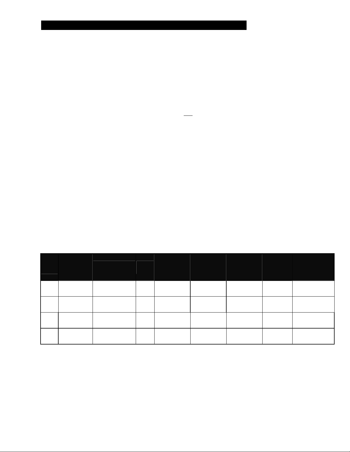
VT4887 & VT4881 Transducer Complement:
Nominal
Model
HF
MF
LF
VLF
1
PASSIVELY CROSSED OVER MID/HIGH FREQUENCY SECTION.
2
LF SECTION HAS TWO 8” COMPONENTS WIRED IN PARALLEL.
3
SINGLE COMPONENT WITH TWO VOICE COILS INDEPENDENTLY WIRED.
2407H
2104H
2168J
2256G
Speakon NL8
Terminals
Pins 4±
Pins 4±
Pins 3±
Pins 1± & 2±
2
Per
box
1
1
3
Impedance
per
Transducer
x 2
x 4 8Ω 8Ω 50W 200W 450W
x 2
x 1 2 x 8Ω 8Ω + 8Ω 600W 2400W 1200W
8Ω 8Ω
16Ω 8Ω
Nominal
Impedance
per
Passband
AES Power
100 HR
Rating per
Transducer
25W 100W 450W
350W 1400W 1000W
Peak
Power
Rating per
Transducer
Recommended
Power per
Passband
Page 5
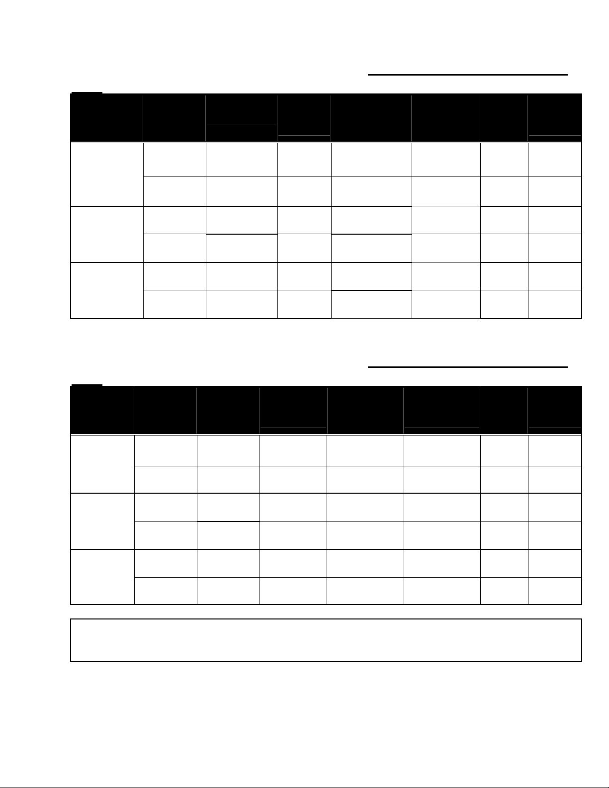
Amplifier Configurations:
5002
Amplifier
Channel
Ch 1.
MA-5002VZ
Ch2.
Ch 1.
MA-5002VZ
Ch2.
Ch 1.
MA-5002VZ
Ch2.
Speakon NL8
Terminals
Pins 4±
Pins 4±
Pins 3± 4 x 2168J
Pins 3± 4 x 2168J
Pins 1± & 2± 1 x 2256G
Pins 1± & 2± 1 X 2256G
Driving
4 x 2407H
& 8 x 2104H
4 x 2407H
& 8 x 2104H
Nominal
Impedance
at Pins
4Ω
4Ω
4Ω
4Ω
4Ω
4Ω
* 6 dB of headroom required for extended bandpass.
Amplifier Power
Rating at
Nominal
Impedance
1800W 900W 54V -3
1800W 900W 54V -3
1800W 900W 134V 4
1800W 900W 134V 4
1800W 900W 86V -2*
1800W 900W 86V -2*
4 x VT4887 & 2 VT4881 / 3 MA-
Power
Available to
each
Bandpass
Bandpass
Peak
Voltage
Vac
Limiter
Threshold
dBu
Amplifier Configurations: 4 x VT4887 & 2 VT4881 / 3 MA-
3600
Amplifier
Channel
Ch 1.
MA-3600 VZ
Ch2.
Ch 1.
MA-3600 VZ
Ch2.
Ch 1.
MA-3600 VZ
Ch2.
EASY: 1 X MA-3600 = 2 VT4887
1 X MA-3600 = 2 VT4881
Speakon NL8
Terminals
Pins 4±
Pins 4±
Pins 3± 4 x 2168J
Pins 3± 4 x 2168J
Pins 1± & 2± 1 x 2256G
Pins 1± & 2± 1 X 2256G
Driving
4 x 2407H
& 8 x 2104H
4 x 2407H
& 8 x 2104H
Nominal
Impedance at
Pins
4Ω
4Ω
4Ω
4Ω
4Ω
4Ω
Amplifier Power
Rating at
Nominal
Impedance
1120W 560W 54V -3
1120W 560W 54V -3
1565W 783W 134V 4
1565W 783W 134V 4
1565W 1565W 86V 1
1565W 1565W 86V 1
Power Available
to each
Bandpass
Bandpass
Peak
Voltage
Vac
Limiter
Threshold
dBu
Page 6
 Loading...