


 Loading...
LSR4328P, LSR4326P
Studio Monitors
Owner’s Manual
ii

Important
Safety Instructions
1.Read these instructions.
2.Keep these instructions.
3.Heed all warnings.
4.Follow all instructions.
5.Do not use this apparatus near water.
6.Clean only with dry cloth.
7.Do not block any ventilation openings. Install in accordance with manufacturer’s instructions.
8.Do not install near any heat sources such as radiators, heat registers, stoves or other apparatus that produce heat.
9.Do not defeat the safety purpose of the grounding type plug. A polarized plug has two blades with one wider than the other. A grounding type plug with two blades and a third grounding prong. The wide blade or the third prong is provided for your safety. If the provided plug does not fit into your outlet, consult an electrician for replacement of the obsolete outlet.
10.Protect the power cord from being walked on or pinched particularly at plugs, convenience recepticle and the point where the power cord connects to the apparatus.
11.Only use attachments/accessories specified by the manufacturer.
12.Use only with the cart, stand, tripod bracket, or table specified by the manufacturer, or sold with the apparatus. When a cart is used, use caution when moving the cart /apparatus combination to avoid injury from tip-over.
13.Unplug this apparatus during lightning storms or when unused for long periods of time.
14.Refer all servicing to qualified service personnel. Servicing is required when the apparatus has been damaged in any way, including: power-supply cord or plug is damaged, liquid has been spilled or objects have fallen into the apparatus, the apparatus has been exposed to rain or moisture, does not operate normally, or has been dropped.
15.The appliance coupler of the power supply cord is used as the ultimate disconnect device from the mains. The appliance coupler shall remain readily operable.
16.The apparatus shall be connected to mains socket outlet with a protective earthing connection.
WARNING:
•To reduce the risk of fire or electrical shock, do not expose the apparatus to rain or moisture.
•The apparatus shall not be exposed to dripping or splashing and no objects filled with liquids, such as vases, shall be placed on the apparatus. As with any electronic product, use care not to spill liquids into any part of the system. Liquids can cause a failure and/or a fire hazard.
Explanation of Graphic Symbols
The exclaimation point within an equilateral triangle is intended to alert the users to the presence of important operating and maintenance (servicing) instructions in the literature accompanying the product.
The lightning flash with the arrowhead symbol, within an equilateral triangle, is to alert the user to the presence of insulated “dangerous voltage” within the products enclosure that may be of sufficient magnatude to constitute a risk of electric shock to humans.
CAUTION: TO REDUCE THE RISK OF
ELECTRONIC SHOCK - DO NOT REMOVE
COVER. NO USER SERVICEABLE PARTS
INSIDE. REFER SERVICING TO QUALI-
FIED PERSONNEL. DO NOT EXPOSE
THIS APPARATUS TO RAIN OR MOIS-
TURE.
ATTENTION: POUR EVITER LES RIS-
QUES DE CHOC ELECTRIQUE, NE PAS
ENLEVER LE COUVERCLE. AUCUN
ENTRETIEN DE PIECES INTERIEURES
PAR L’USAGER. CONFIER L’ENTRETIEN
AU PERSONNEL QUALIFIE. AVIS: POUR
EVITER LES RISQUES D’INCENDIE
OU D’ELECTROCUTION, N’EXPOSEZ
PAS CET ARTICLE A LA PLUIE OU A
L’HUMIDITE.
iii
Table Of Contents |
|
Safety Instructions....................................................................... |
iii |
Introduction.................................................................................... |
1 |
Quick Start ..................................................................................... |
5 |
Reference....................................................................................... |
9 |
Front Panel............................................................................................. |
9 |
Rear Panel............................................................................................ |
16 |
Remote Control .................................................................................... |
18 |
Speaker Placement .............................................................................. |
20 |
AC Power Connections ........................................................................ |
21 |
Network Connections and DIP Switch Settings.................................... |
21 |
Audio Connections ............................................................................... |
23 |
RMC Room Mode Correction ............................................................... |
24 |
Performing An RMC Calibration ........................................................... |
25 |
Equalization.......................................................................................... |
28 |
Restoring Factory Settings ................................................................... |
30 |
LSR4300 Control Center Software....................................................... |
30 |
Appendix A: EQ Presets ............................................................. |
31 |
Appendix B: System Block Diagram ......................................... |
33 |
Appendix C: Wiring Requirements............................................ |
34 |
Appendix D: Mounting Specifications....................................... |
37 |
Appendix E: SPL Calibration...................................................... |
38 |
Appendix F: Error Messages and Troubleshooting................. |
39 |
Specifications.............................................................................. |
41 |
Warranty Statement..................................................................... |
44 |
JBL Professional Contact Information...................................... |
46 |
iv
Introduction - Manual Conventions
Introduction
Congratulations on your purchase of JBL LSR4300 Series Studio Monitors, the most advanced loudspeaker system ever developed for critical listening.
We know that very few people read owner’s manuals from cover to cover, so we’ve organized this one to make it easy to find the information you need.
The Features section on the next page provides a brief overview of the exceptional features of the LSR4300 Series. It’s followed by a QuickStart section, which will get you up and running in a matter of minutes.
Once you’ve got your LSR4300 system powered up and delivering sound, you should turn to the Reference section, which describes every feature and function of the LSR4300 in detail. Finally, we’ve included a number of technical appendices and specifications at the end of this manual.
Note that this manual covers the model LSR4328P and LSR4326P Studio Monitors. Separate owner’s manuals are provided for the model LSR4312SP Subwoofer and for the LSR4300 Control Center software.
Manual Conventions
The following conventions will be used in this owner’s manual:
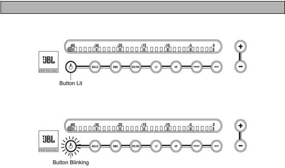
Especially important tips and cautions will be presented like this.
Indicates that a button is lit.
Indicates that a button is blinking.
1

Introduction - Features
Indicates that an LED is lit green.
Indicates that an LED is lit red.
Features
The LSR4300 Series combines stunning sound and legendary JBL design with innovative new technologies. The end result is a product that is nothing short of revolutionary – a monitoring system suitable for use in the most demanding music, broadcast, and postproduction applications.
RMC™ Room Mode Correction
The biggest challenge for anyone producing audio is creating a mix that sounds great on all playback systems. If you think of a monitoring system as a kind of “lens” through which you hear sound, the object is to have the lens be crystal-clear and transparent so that it imparts no coloration whatsoever to the signal being played back. However, every loudspeaker system, no matter how well designed, interacts with the room in which it is installed. Lack of correct acoustic treatment (or, worse yet, lack of any treatment at all) can result in anomalies such as resonant frequencies and low-frequency “standing waves” – the aural equivalent to the lens being “smeared.” Trying to create a mix in such an environment can be as frustrating and difficult as trying to paint a masterpiece while blindfolded.
JBL’s exclusive second generation RMC™ Room Mode Correction technology is designed to solve the problem. Apowerful onboard computer in each LSR4300 Series monitor automatically analyzes the frequency response of your room and compensates for low frequency inaccuracies in the listening space by precisely inserting filters so that low frequency signals arrive at the mix position with the intended frequency response. In effect, the LSR4300 Series goes “beyond accurate,” allowing you to eliminate the guess-work and create reliable mixes that translate to any environment. Additionally, the RMC system trims the level of each speaker to compensate for differences in placement relative to the mix position, ensuring balanced mixes.
2
Introduction - Features
HiQnet™ Networking
The LSR4300 Series also incorporates the new Harman HiQnet™ protocol that networks all the speakers in a system together and allows full control from the provided wireless remote control or from any computer via a standard USB connection and LSR4300 Control Center Software. With the push of a button or the click of a mouse you can change the system level, choose from any of three different inputs (one analog and two digital), mute and solo individual speakers, and make low and high frequency EQ adjustments.
LSR Linear Spatial Reference Design
The LSR4300 builds on the Linear Spatial Reference technology that has made our LSR6300 Series of studio monitors so popular in recording, broadcast, and postproduction facilities worldwide. The exact geometry of the wave guide, the interaction of the woofer and tweeter, and the final assembly of the injection-molded parts has been redesigned from the ground up to provide accurate off-axis as well as on-axis listening, within a window of +/-30 degrees horizontal, +/- 15 degrees vertical. Attention to these critical aspects results in neutral mid and high frequency response at the mix position and a sound which is smooth and accurate in a wide variety of acoustic spaces.
Surround Smart
The LSR4300 Series is ideal for surround sound use. Up to eight main speakers – any combination of LSR4326 6-inch and LSR4328 8-inch models – and up to two LSR4312SP subwoofers can be easily configured for LCRS, 5.1, 6.1, 7.1 SDDS and larger mixing and monitoring applications.
Once all LSR4300 monitors are in place, RMC and HiQNet automatically aligns the entire system, setting relative volume so that the sound from all channels is balanced when it arrives at the mix position. The end result is precise imaging regardless of each monitor’s actual physical placement.
In addition, the ability to centrally control the volume of all the speakers (via the supplied wireless remote control or LSR4300 Control Center software) is particularly useful in surround sound applications where the recording system does not provide a multi-channel monitor volume control, or where adjustable volume is not available when using the
mixing system’s digital outputs. Similarly, the ability to selectively mute or solo channels and to remotely switch between three digital and analog input sources enhances system capabilities by allowing you to monitor not only the main recording system, but also any two additional connected sources such as DVD and CD players, multi-channel processors and encode-decode units. This alleviates the need to purchase additional outboard monitoring hardware.
Selectable Inputs
In this age of digital workstations and control surfaces, it isn’t enough to simply provide an input jack. The LSR4300 offers three separate inputs: stereo high-resolution 96 kHzAES/ EBU and S/PDIF digital inputs, as well as dual balanced analog XLR and ¼-inch inputs with selectable +4dBu / -10dBV sensitivity. This allows it to accommodate a wide range of input sources, including digital workstations, CD players, DVD players, and multi-channel processors. What’s more, you can easily select between inputs with the push of a single button (on either the front panel or the wireless remote) or click of a mouse (via an attached computer and the included LSR4300 Control Center software).
3
Introduction - Features
Onboard Bi-amplification
LSR4300 Series monitors are self-powered, eliminating the need for external amplifiers. Perfectly matched bi-amplification is provided onboard, with 150 watts of power for the woofer and 70 watts for the high frequency transducer.
Other Features
•Custom designed transducers specially engineered to deliver clean, crisp sound. The LSR4328P model features an 8-inch low frequency woofer, while the LSR4326P model offers a 6.25-inch woofer, both coupled with a 1-inch soft-dome high frequency transducer. All transducers are self-shielded, with Neodymium motor structures for exceptional transient response and superb power handling.
•Advanced front-panel user interface allows control of system functions such as volume, input selection, user EQ and EQ presets, RMC calibration and bypass, individual speaker solo, and brightness level of the meter and buttons.
•Front panel meters show continuous output levels in dBFS to serve as a visual reference of the speaker’s contribution when measured at the mix position.
•Integrated mounting points allow wall mounting of speakers when space limitations prohibit the use of speaker stands.
•Built-in side handles make positioning and transporting of speakers easier.
4

Quick Start
Quick Start
Each LSR4300 speaker includes:
•One speaker
•CAT5 networking cable
•AC power cord
•This owner’s manual
The LSR4326/PAK and the LSR4328P/PAK include:
•Two speakers, each with the above items
•LSR4300Accessory Kit containing:
oCalibration microphone and mic clip
oInfrared wireless remote control
oLSR4300 Control Center Software
o16-foot USB Cable
oTwo network terminators
oTwoAAABatteries
Here are simple step-by-step instructions to get you up and running quickly:
1.Unpack the speakers. To avoid damage to the speaker elements, open the top of the box, keep the Styrofoam end cap on, and roll the box upside down. The box can then be slipped off. (This also works in reverse for repacking the units.)
Be sure to not grasp the monitors from the front. A stray hand or finger can cause damage to the high frequency transducer that is located near the top of the cabinet on the front baffle.
2.Position each speaker in the room. (See page 30 in this manual for speaker placement tips.)
5
Quick Start
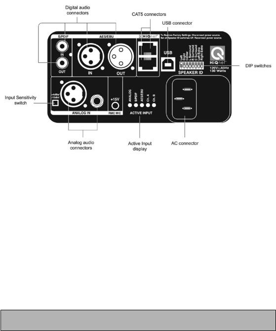
LSR4300 Rear Panel
3.Connect each speaker to a suitable power source using the suppliedAC power cable. (See page 23 in this manual for more information.)
4.Connect the speakers together in any order using the supplied CAT5 cable. Plug one end of the cable into either of the two HiQnet ports on one speaker and the other end into a HiQnet port on another speaker until all speakers are connected. Connect the two supplied ethernet terminators to the first and last speakers in the chain. (See page 21 in this manual for more information on networking your LSR4300 monitors.)
5.Set the Network ID DIP switch on the rear panel of each speaker so that it corresponds to the channel for which the speaker is to be used. For example, place the DIP switch labeled LEFT in the up (ON) position for the speaker reproducing the left channel, and place the DIP switch labeled RIGHT in the up (ON) position for the speaker reproducing the right channel. (See page 22 in this manual for more information.)
Make sure that one, and only one, DIP switch is placed in the up (ON) position for each speaker. One speaker in the system must have the LEFT DIP switch set to the ON position.
6.Make all required audio connections to the rear panel of your monitors. Both the LSR4328P and LSR4326P models are both able to accommodate one analog and two digital input signals. (See page 23 in this manual for more information on audio connections.)
a.If you are connecting an analog signal (i.e. from the line level analog outputs of a mixing console, workstation, CD player, or DVD player), use
appropriate cabling to make a connection between the device and either the rear panelAnalog XLR connector or ¼″ connector, then set the rear panel Input Sensi-
6
Quick Start
tivity switch to +4dBV (switch IN) or -10dBu (switch OUT) to match the nominal level of the signal source. If you don’t know how to set the switch, consult the documentation for the signal source. Most professional devices operate at +4dBV while most consumer devices operate at -10dBu. (See page 24 in this manual for a wiring diagram.)
Do NOT make connections to both the XLR and ¼″ analog connectors; use one or the other.
b.If you are connecting digital signals (i.e., from a digital console or workstation, or from the digital outputs of a CD or DVD player or processor), use appropriate cabling to make a connection between the device and the rear panelAES/EBU (XLR) or S/PDIF (phono) input of the speaker designated to carry the LEFT channel (i.e., the left speaker in a stereo setup). Then use appropriate cabling to make a connection between the rear panelAES/EBU (XLR) or S/PDIF (phono) output of the left speaker and the rear panelAES/EBU or S/PDIF input of the speaker designated to carry the RIGHT channel (i.e., the right speaker in a stereo setup). (See page 24 in this manual for a wiring diagram.)
When using digital audio inputs, the rear panel DIP switch settings determine which channel of the stereo AES/EBU or S/PDIF signal will be reproduced by each speaker.
LSR4300 Front Panel
7.Press the front panel INPUT button on any speaker so that it begins blinking. While it is still blinking, press the + / - controls on any speaker to select the desired input. The front panel LEDs and the rear panelACTIVE INPUT display shows which of the three inputs (Analog, S/PDIF, orAES/EBU) is currently selected. If a digital input is selected, the rear panelACTIVE INPUT display also shows which channel is being reproduced by that speaker.
7

Quick Start
8.Power up your signal source, then press the front panel POWER button on any speaker. All speakers in the system will power on (the JBL Logo will go from dimly to brightly lit.)
To avoid “thumps” which can damage your speakers, always power up the signal source FIRST and your LSR4300 monitors LAST.
9.Set the initial speaker volume by pressing the + / - controls on any speaker. All speakers in the system will go to the designated volume. As the volume is increased, additional LEDs light. We recommend beginning with a modest volume setting, so that only the first ten LEDs or so (up to the “-20”) mark are lit.
10.Play a signal source and adjust the final speaker volume to a comfortable listening level by pressing the + / - controls on any speaker.
11.If your LSR4300 system is brand new, the RMC button on the front panel of all speakers will be lit, indicating that Room Mode Correction has not yet been performed. To calibrate your speakers with RMC, begin by attaching the provided calibration microphone to a mic stand and place the mic at the mix position, oriented vertically. Then connect the microphone to the Left speaker’s RMC MIC rear panel input.
To perform an RMC analysis, the calibration microphone must be connected to the speaker designated as “Left” (LEFT DIP switch up).
12.Press and hold the RMC button on any speaker, then walk to a spot in the room where you are not blocking the path between the microphone and any speaker. Each speaker will emit a reference tone in turn and its meter will show a left-to-right “chase” pattern that indicates the system is calibrating. When the “chase” pattern on the meters stops, the process is complete. You can compare the effects of RMC with the uncorrected response by pressing the RMC button on the front panel of any speaker. When the button is lit, RMC correction is being bypassed and you hear the uncorrected response; when the RMC button is unlit, the RMC is active and compensating for any acoustic deficiencies in your listening environment. (See page 25 in this manual for a step-by-step description of the RMC calibration procedure.)
The RMC procedure produces a fairly loud swept sine wave calibration tone that can surprise you when you hear it for the first time. After pressing the RMC button, move away from the speaker. There is a five second delay prior to the sounding of the calibration tone.
13.Place the provided batteries in the wireless remote control, and, if you want to establish computer control over your LSR4300 system, make a USB connection between your computer and the LEFT speaker and then install the provided LSR4300 Control Center Software.
14.Finally, put on some good music to listen to and take a few moments to read the rest of this manual to acquaint yourself with all the features of your JBL LSR4300 system. Enjoy!
8
Reference - Overview/Front Panel
Reference
Overview
LSR4328P/4326P Front |
LSR4328P/4326P Rear |
Front Panel
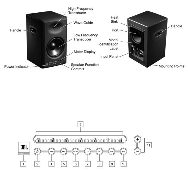
LSR4328P/4326P Front Panel
The controls and displays on the front panel of the LSR4300 allow you to adjust and view various speaker settings. Below is a listing and description of each.
1.Power Indicator – The JBL logo lights at two different levels. It is illuminated dimly whenever the LSR4300 is connected to anAC power source, indicating the speaker is in “standby” status. It is illuminated at full brightness when the speaker is powered up and active.
9
Reference - Front Panel
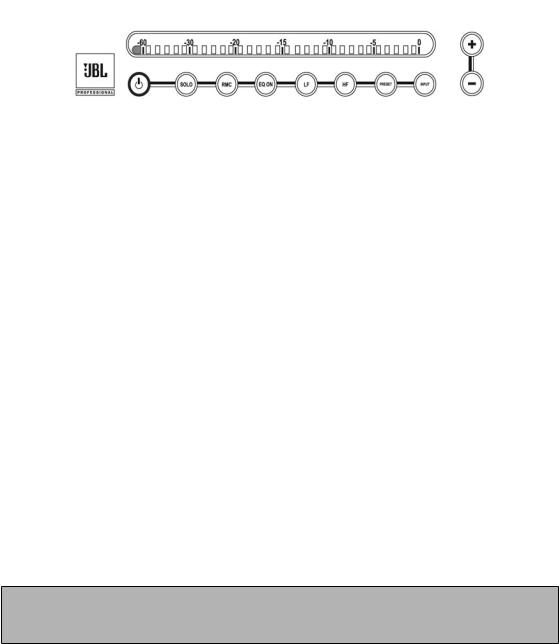
2.Power –After connection to anAC power source, press this button to turn the speaker on. If networked together with other speakers, all speakers will turn on simultaneously. Press the button again to return the speaker to a low-power stand-by mode, where the internal amplifiers are turned off and all user functions are deactivated. As shown below, when the speaker is powered on and active, the JBL logo will be brightly lit (see #1 above) and the left-most meter segment will be lit:
3.Meter Display – In combination with front panel buttons, the meter is used to display the current setting and status of the following functions:
•SOLO function (see #4 below)
•Progress of RMC calibration process (see #5 below)
•LF and HF EQ boost and attenuation (see #6, #7 and #8 below)
•EQ preset selection (see #9 below)
•Input source selection (see #10 below)
•Overall system volume (see #11 below)
•Meter and button brightness (see #11 below)
•Error conditions
The meter has 31 three-color segments that can illuminate in green, amber or red. For many of the above operations, all 31 segments light green only. However, when audio signal is being reproduced by the speaker, all three colors are used and the meter is calibrated to indicate the continuous output in decibels (dB) below the speaker’s full output capability. Green LEDs indicate signal 8 dB (or more) below clipping; amber, approximately 7 to 4 dB below clipping; and red, approximately 3 to 0 dB below clipping. The segment furthest to the right (“0”) illuminates red when the input signal is has reached its maximum value (greater than -1.5 dBFS) and causes clipping of the electronics.
The LSR4300 models include protective limiting. Limiting occurs when the output signal exceeds -2 dBFS or the second LED from the right is illuminated (in the LSR4328P) or
-5 dbFS or the fifth LED from the right is illuminated (in the LSR4326P).
10

Reference - Front Panel
You can calibrate your LSR4300 system so that the meter display will show how much SPL the speaker is contributing at the listening position. For more information, see Appendix E on page 38 in this manual.
4.SOLO – Press this button to mute the signal on all other speakers.As shown below, when this function is active, the SOLO button will flash on the selected speaker.
At the same time, the SOLO buttons on all other networked speakers (those that are muted) will light steadily, and their left-most meter segments will flash to indicate a muted state:
To end solo and unmute all other networked speakers, press the SOLO button for that speaker again.
All front panel button actions can be cancelled at any time simply by pressing the button a second time.
5.RMC Room Mode Correction – This button is used both to initiate an RMC calibration and to bypass it after it has been performed (in order to compare the results of
RMC with the uncorrected signal). To initiate RMC calibration, press this button and hold it for three seconds or longer. (During calibration, the button flashes.) For more information about RMC and the RMC calibration procedure, see pages 24 through 28 in this manual.
11
Reference - Front Panel
When a brand new LSR4300 speaker is first powered on or if its factory settings have been recalled (see page 30 in this manual), the RMC button lights steadily to indicate that an RMC calibration needs to be performed. For more information, see page 25 in this manual.
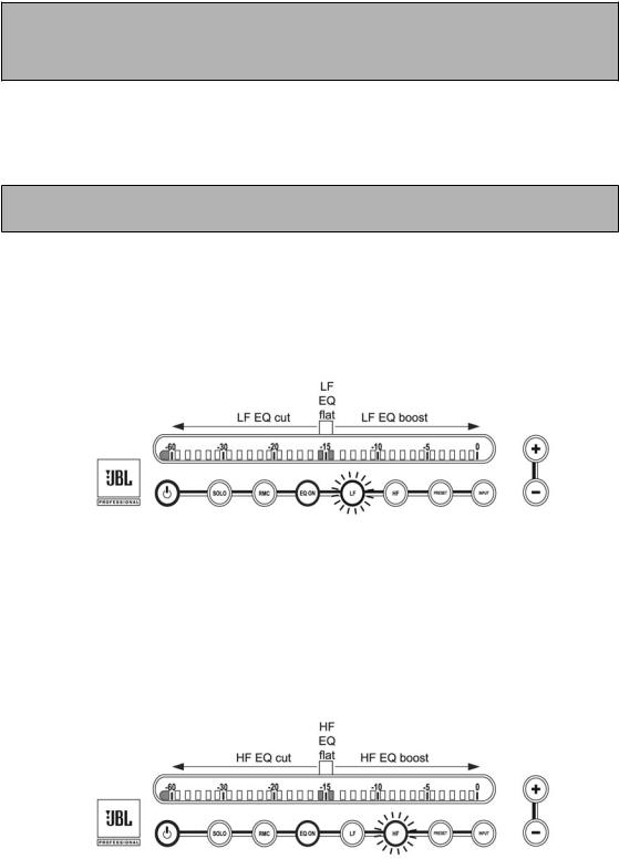
6.EQ – Pressing this button allows you to enable or bypass the LSR4300 equalization. When the button is lit, EQ is active.
When EQ is ON, the LF and/or HF buttons will also light if the current setting includes LF or HF boost or cut.
7.LF (Low Frequency) boost / cut –Allows you to apply +/- 2 dB of low frequency equalization. Press this button to activate LF EQ; it will flash. While flashing, press the + button to increase the amount of LF EQ in 0.25 dB steps or press the – button to decrease the amount of LF EQ in 0.25 dB steps. For more information, see page 28 in this manual.
Once set, the LF and EQ buttons will remain illuminated to indicate that LF equalization has been applied.
8.HF (High Frequency) boost / cut –Allows you to apply +/- 2 dB of high frequency equalization. Press this button to activate HF EQ; it will flash. While flashing, press the + button to increase the amount of HF EQ in 0.25 dB steps or press the – button to decrease the amount of HF EQ in 0.25 dB steps. For more information, see page 28
in this manual.
Once set, the HF and EQ buttons will remain illuminated to indicate that HF equalization has been applied.
12
Loading...