


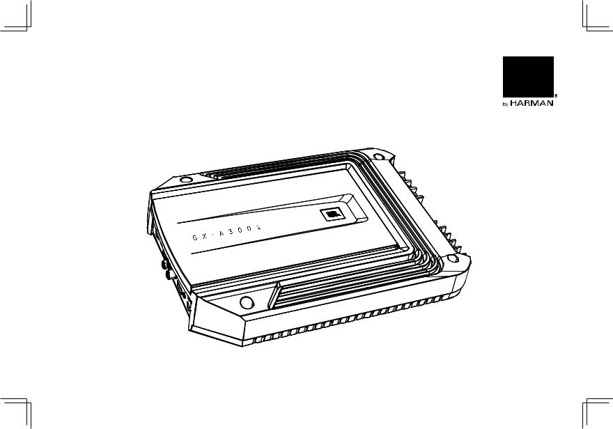
GX-A604/GX-A602/GX-A3001
power amplifier
OWNER’S MANUAL
Svenska Nederlands Русский Italiano Deutsch Español Français English
Dansk
introduction
THANK YOU for purchasing a JBL® GX-series amplifier. So we can better serve you should you require warranty service, please retain your original sales receipt and register your amplifier online at www.jbl.com.
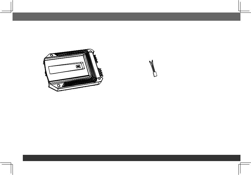
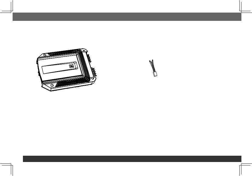
included items
GX-Series Amplifier (x 1) |
Speaker-level input harness |
(GX-A602, GX-A3001 x 1) |
|
|
(GX-A604 x 2) |
location and mounting
Although these instructions explain how to install GX-series amplifiers in a general sense, they do not show specific installation methods that may be required for your particular vehicle. If you do not have the necessary tools or experience, do not attempt the installation yourself. Instead, please ask your authorized JBL car audio dealer about professional installation.
Installation Warnings and Tips
IMPORTANT: Disconnect the vehicle’s negative (–) battery terminal before beginning the installation.
•Always wear protective eyewear when using tools.
•Check clearances on both sides of a planned mounting surface. Be sure that screws or wires will not puncture brake lines, fuel lines or wiring harnesses, and that wire routing will not interfere with the safe operation of the vehicle.
•When making electrical connections, make sure they are secure and properly insulated.
•If you must replace any of the amplifier’s fuses, be sure to use the same type of fuse and current rating as that of the original.
2
 English
INSTALLATION LOCATION
Amplifiers need air circulation to stay cool. Select a location that provides enough air for the amp to cool itself.
•Suitable locations are under a seat (provided the amplifier doesn’t interfere with the seat adjustment mechanism), in the trunk, or in any other location that provides enough cooling air.
•Do not mount the amplifier with the heatsink facing downward, as this interferes with the amplifier’s convection cooling.
•Mount the amplifier so that it will not be damaged by the feet of backseat passengers or shifting cargo in the trunk.
•Mount the amplifier so that it remains dry – never mount an amplifier outside the car or in the engine compartment.
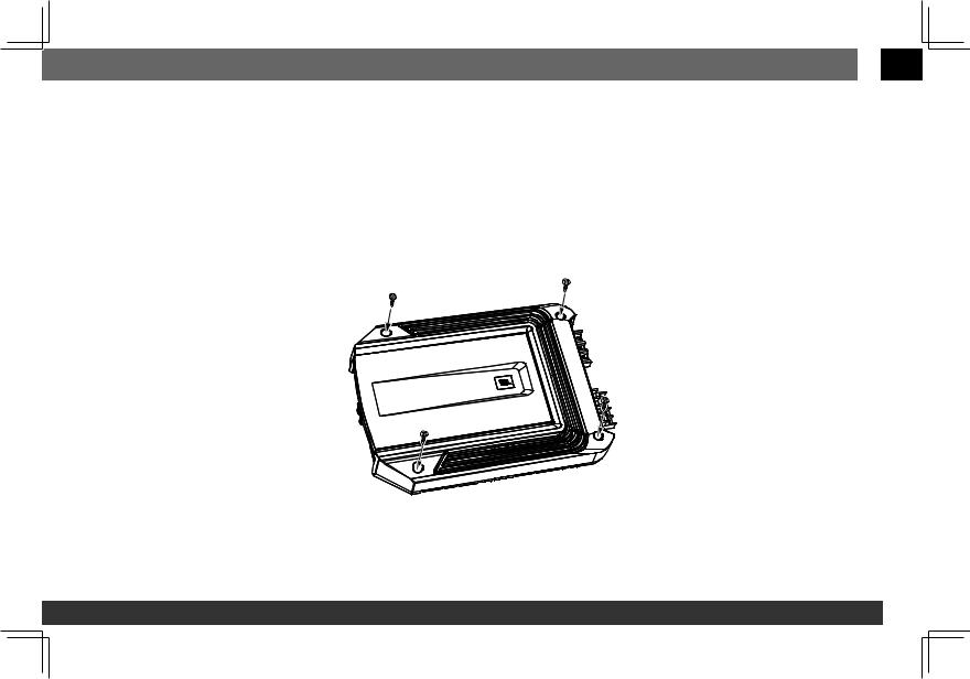
MOUNTING THE AMPLIFIER
NOTE: You may find it more convenient to make all of the connections to the amplifier before you permanently mount it to the vehicle.
1.Select a suitable mounting location as described above.
2.Using the amplifier as a template, mark the locations of the mounting holes on the mounting surface.
3.Drill pilot holes in the mounting surface.
4.Attach the amplifier to the mounting surface with four appropriate mounting screws of your own choice. We suggest using #8 Phillips-head sheet metal screws. Make sure the amplifier is mounted securely.
www.jbl.com 3
power and ground connections
important: Disconnect the vehicle’s negative (–) battery terminal before beginning the installation.
The GX series amplifiers are capable of delivering high power levels, and require a heavy-duty and reliable connection to the vehicle’s electrical system to achieve optimal performance. Please adhere to the following instructions carefully.
Using the Connectors
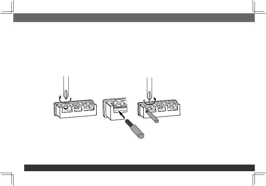
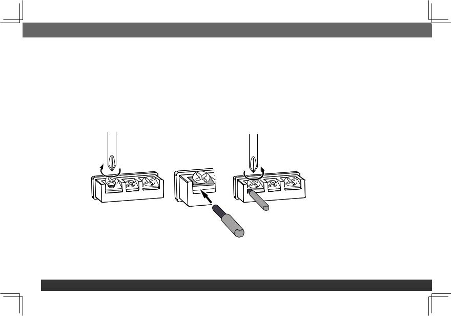
GX-series amplifiers use the same type of screw terminals for power and speaker connections. This type of terminal is easy to use and allows the easy connection of large-gauge wire.
To use the connectors, use a Phillips screwdriver to loosen the connector’s set screw, insert the bare wire and tighten the set screw to secure the wire in the connector, as shown in the illustration below.
Loosen Screw |
Insert Wire |
Tighten Screw |
|
Under Washer |
|
IMPORTANT: Make sure the (+) and (–) speaker bare wires do not touch each other or the other terminal at both the amplifier terminals and speaker terminals. Touching wires can cause a short circuit that can damage the amplifier.
4
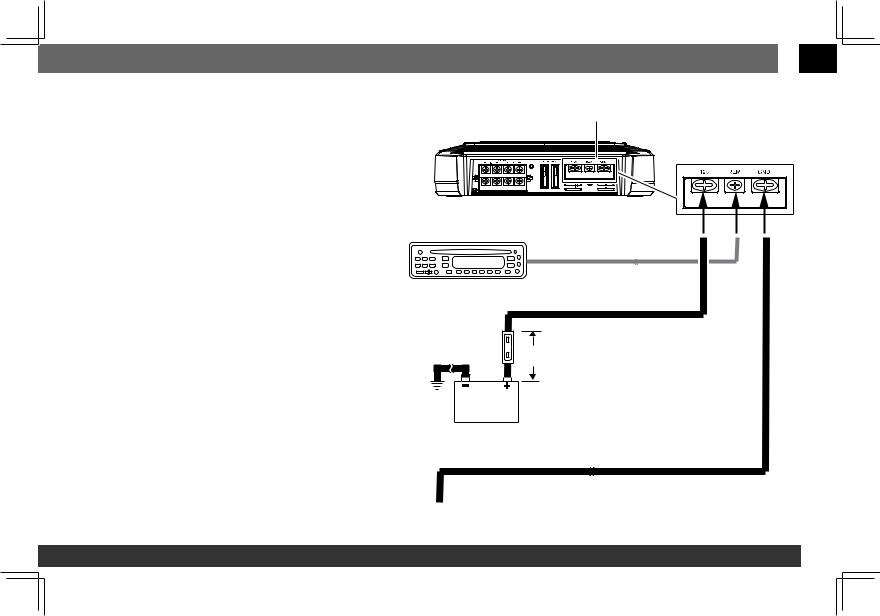
GROUND (GND) CONNECTION
Connect a wire (minimum 10 AWG – 5.3 mm2) from the amplifier’s GND terminal directly to a solid point on the vehicle’s chassis.
•For a good connection, use sandpaper to clear the paint from the metal surface at this chassis location. Use a star-type lock washer to secure the wire’s connection.
POWER (12 V) CONNECTION
1.Connect a wire (minimum 10 AWG – 5.3 mm2) directly to the battery’s positive (+) terminal.
2.Install a fuse holder for a 50 A fuse (GX-A604, GX-A3001) or a 30 A fuse (GX-A602) on this wire within 18" (46 cm) of the battery’s (+) terminal. Do not install the fuse in the holder at this time.
3.Route this wire to the amplifier’s location and connect it to the amplifier’s +12 V terminal.
Be sure to use appropriate grommets whenever routing wires through the firewall or other sheet metal. IMPORTANT: Failure to adequately protect the positive wire from potential damage may result in a vehicle fire.
4.When you are finished routing and connecting this wire, install the appropriate fuse in the holder you installed near the battery.
(GX-A604, GX-A3001 – 50 A fuse; GX-A602 – 30 A fuse)
 English
Power
Connectors
Audio System
Head Unit Remote Turn-On
(optional)
>#18 AWG (0.82 mm2) Wire
>#10 AWG (5.26 mm2) Wire
50 A Fuse (GX-A604/GX-A3001) |
|
30 A Fuse (GX-A602) |
18" (46 cm) |
|
>#10 AWG (5.26 mm2) Wire
Chassis Ground
 (bare metal)
www.jbl.com 5
speaker and input connections
Always connect the (+) speaker terminal on the amplifier to the (+) terminal on the speaker and the (–) speaker terminal on the amplifier to the (–) terminal on the speaker.
IMPORTANT: Make sure the (+) and (–) bare wires do not touch each other or the other terminal at both the amplifier terminals and speaker terminals. Touching wires can cause a short circuit that can damage the amplifier.
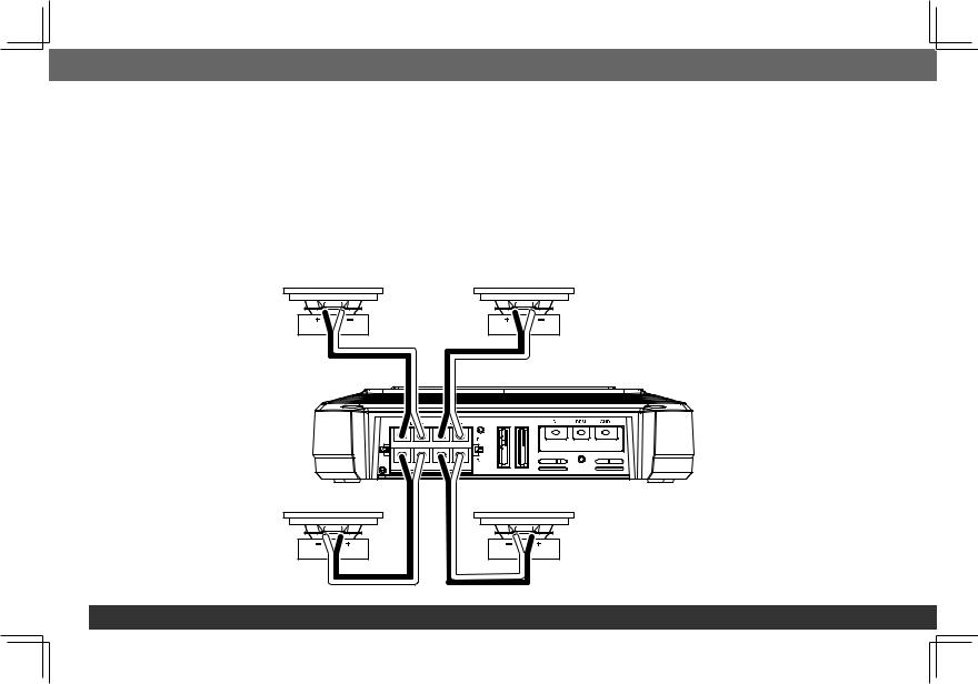
GX-A604 speaker connections: 4-Channel operation
Minimum speaker impedance: 2 ohms (each)
•Connect the front speakers to the FL and FR (+) and (–) terminals.
•Connect the rear speakers to the RL and RR (+) and (–) terminals.
Front Left Speaker |
Front Right Speaker |
Speaker |
Rear Left Speaker |
Rear Right Speaker |
6
 English
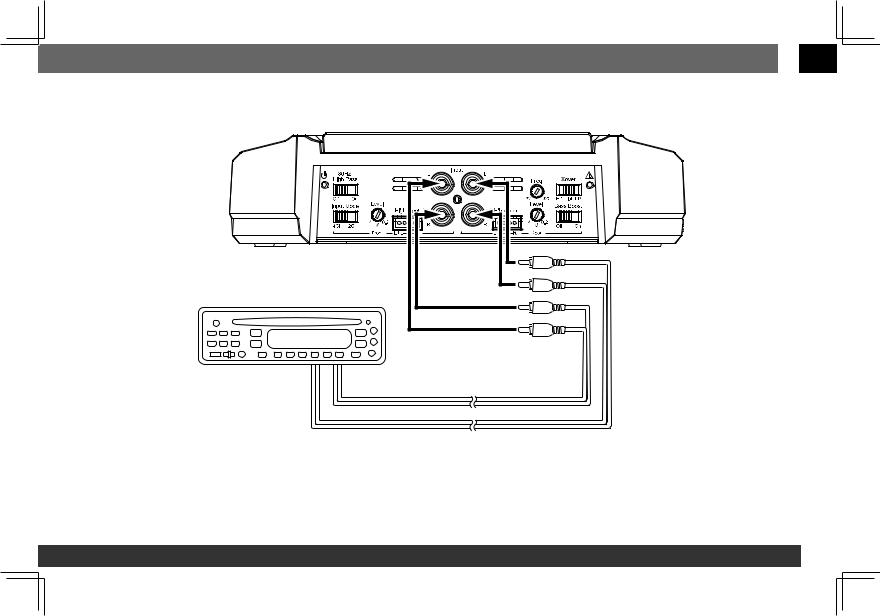
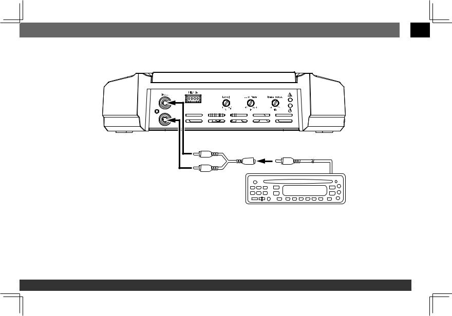
GX-A604 INPUT CONNECTIONS: 4-CHANNEL OPERATION
Connect your source unit or processor’s front and rear left and right outputs to the amplifier’s inputs as shown in the illustration.
Source Unit |
Front Line Outputs
Rear Line Outputs
See Set The Crossover Controls, on page 20, for information about setting the amplifier’s controls for 4-channel operation.
To use the speaker-level inputs instead of the line-level inputs, see Using The Speaker-Level Inputs, on page 12.
www.jbl.com 7
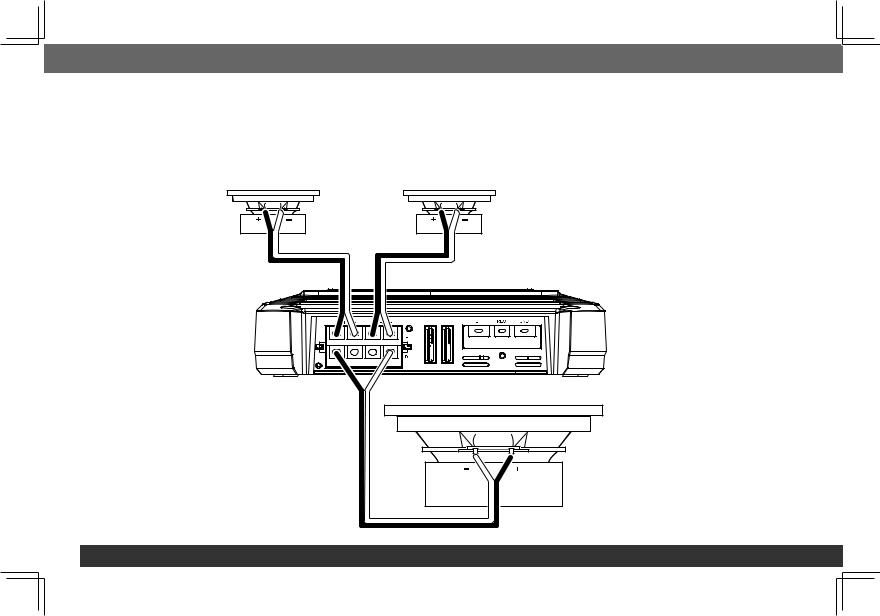
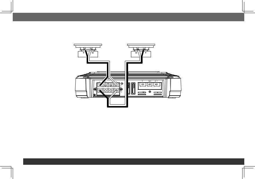
GX-A604 SPEAKER CONNECTIONS: 3-CHANNEL OPERATION
Minimum speaker impedance: 2 ohms each (left & right speakers); 4 ohms (subwoofer)
•Connect the left and right speakers to the FL and FR (+) and (–) terminals
•Connect the subwoofer to the RL (+) and RR (–) terminals. (The rear-channel Bass Boost control makes the rear channels preferable for subwoofer connection. See Set The Bass Boost, on page 23.) NOTE: You can connect two 2-ohm subwoofers in series to maintain the required 4-ohm mimimum impedance for the subwoofer channel.
Front Left Speaker |
Front Right Speaker |
Speaker |
Subwoofer
8
 English
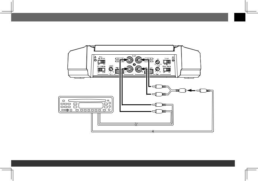
GX-A604 INPUT CONNECTIONS: 3-CHANNEL OPERATION
Connect your source unit or processor’s line outputs as shown in the illustration below. Set the input mode switch in the "4CH" position NOTE: Use a "Y"-adapter to connect the source unit’s subwoofer output to the amplifier’s rear left and right input jacks.
"Y"-Adapter |
Source Unit |
Front Line Outputs
Subwoofer Line Output
See Set The Crossover Controls, on page 20, for information about setting the amplifier’s controls for 3-channel operation.
To use the speaker-level inputs instead of the line-level inputs, see Using The Speaker-Level Inputs, on page 12.
www.jbl.com 9
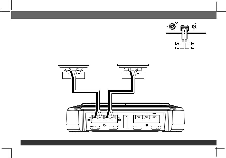
GX-A604 speaker connections: 2-channel operation
Minimum speaker impedance: 4 ohms (each)
Connect the left and right speakers as shown in the illustration below.
Left Speaker |
Right Speaker |
10
 English
GX-A604 INPUT CONNECTIONS: 2-CHANNEL OPERATION
Connect your source unit or processor’s line outputs as shown in the illustration below. Use only the front left and right input connections and make sure that the Input Mode switch is set in the "2CH" position.
Source Unit |
Front Line Outputs
See Set The Crossover Controls, on page 20, for information about setting the amplifier’s controls for 2-channel operation.
To use the speaker-level inputs instead of the line-level inputs, see Using The Speaker-Level Inputs, on page 12.
www.jbl.com 11
Using the speaker-level inputs
If your source unit doesn’t have line-level outputs you can use the included speaker-level input harness to connect the amplifier to the source unit’s speaker outputs. From left to right, the conductors are: L+, L–, R–, R+ (see the illustration to the right). The speaker-level connectors on all GX-series amp models follow this wiring configuration.
Follow the instructions in the previous sections, substituting the speaker-level connectors for the line-level connectors.
GX-A602 speaker Connections; 2-channel operation
Minimum speaker impedance: 2 ohms (each)
Connect the left and right speakers to the FL and FR (+) and (–) terminals.
Front Left Speaker |
Front Right Speaker |
+12V
Speaker
12

 English
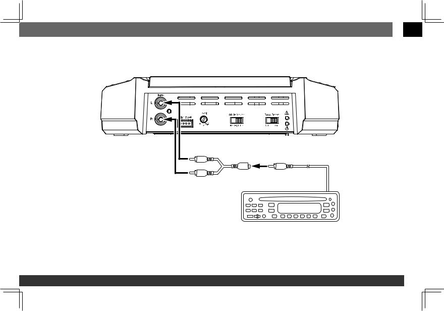
GX-A602 INPUT CONNECTIONS: 2-CHANNEL OPERATION
Connect your source unit or processor’s line outputs as shown in the illustration below.
L+L–R–R+
Line Outputs
Source Unit
See Set The Crossover Controls, on page 20, for information about setting the amplifier’s controls for 2-channel operation.
To use the speaker level inputs instead of the line-level inputs, see Using The Speaker-Level Inputs, on page 12.
www.jbl.com 13
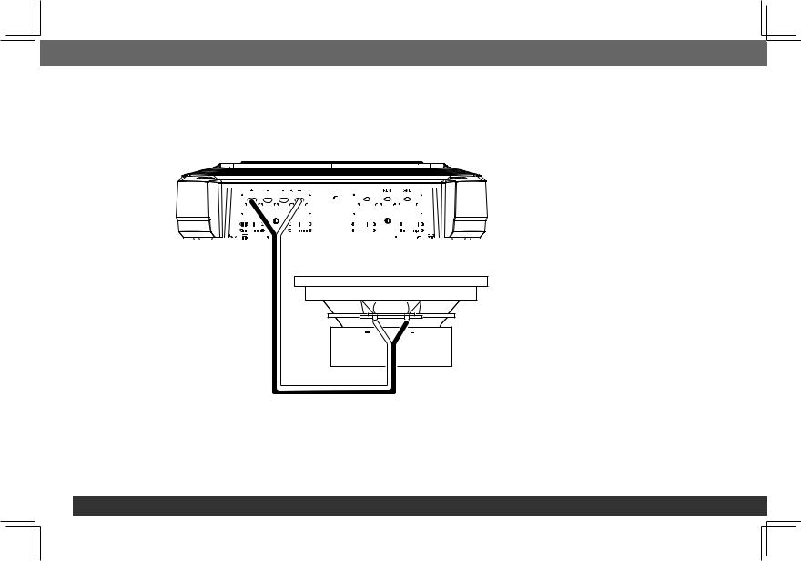
GX-A602 speaker connections: bridged operation
Bridged operation provides a single high-power channel for a subwoofer
Minimum speaker impedance: 4 ohms
Connect the subwoofer to the RL (+) and RR (–) terminals. NOTE: You can connect two 2-ohm subwoofers in series to maintain the required 4-ohm impedance for bridged operation.
|
|
|
|
|
|
|
|
|
|
|
|
|
|
|
|
|
|
|
|
Fuse 25A |
|
+12V |
|
||||||||||||
|
|
|
|
|
|
|
|
|
|
|
|
|
|
|
|
|
|
|
|
|
|
|
|
|
|
|
|
|
|
|
|
|
|
|
|
|
|
|
|
|
|
|
|
|
|
|
|
|
|
|
|
|
|
|
|
|
|
|
|
|
|
|
|
|
|
|
|
|
|
|
|
|
|
|
|
|
|
|
|
|
|
|
|
|
|
|
|
|
|
|
|
|
|
|
|
|
|
|
|
|
|
|
|
|
|
|
|
|
|
|
|
|
|
|
|
|
|
|
|
|
|
|
|
|
|
|
|
|
|
|
|
|
|
|
|
|
|
|
|
|
|
|
|
|
|
|
|
|
|
|
|
|
|
|
|
|
|
|
|
|
|
|
|
|
|
|
|
|
|
|
|
|
|
|
|
|
|
|
|
|
|
|
|
|
|
|
|
|
|
|
|
|
|
|
|
|
|
|
|
|
|
|
|
|
|
|
|
|
|
|
|
|
|
|
|
|
|
|
|
|
|
|
|
|
|
|
|
|
|
|
|
|
|
|
|
|
|
|
|
|
|
|
|
|
|
|
|
|
|
|
|
|
|
|
|
|
|
|
|
|
|
|
|
|
|
|
|
|
|
|
|
|
|
|
|
|
|
|
|
|
|
|
|
|
|
|
|
|
|
|
|
|
|
|
|
|
|
|
|
|
|
|
|
|
|
|
|
|
|
|
|
|
|
|
|
|
|
|
|
|
|
|
|
|
|
|
|
|
|
|
|
|
|
|
|
|
|
|
|
|
|
|
|
|
|
|
|
|
|
|
|
|
|
|
|
|
|
|
|
|
|
|
|
|
|
|
|
|
|
|
|
|
|
|
|
|
|
|
|
|
|
|
|
|
|
|
|
|
|
|
|
|
|
|
|
Subwoofer
14
 English
GX-A602 INPUT CONNECTIONS: BRIDGED OPERATION
Connect your source unit or processor’s subwoofer line output to the amplifier’s left input, as shown in the illustration below. NOTE: Use a "Y"-adapter to connect the source unit to the amplifier’s left and right input jacks.
L+L–R–R+ |
|
"Y"-Adapter |
Subwoofer |
Output |
|
Source Unit |
|
See Set The Crossover Controls, on page 20, for information about setting the amplifier’s controls for bridged operation.
To use the speaker-level inputs instead of the line-level inputs, see Using The Speaker-Level Inputs, on page 12.
www.jbl.com 15

gx-a3001 speaker connections
Minimum speaker impedance; 2 ohms (single subwoofer); 4 ohms (2 subwoofers)
The GX-A3001 has two parallel sets of speaker connectors, allowing you to connect two subwoofers.
|
|
|
|
|
|
|
|
|
|
|
|
|
|
|
|
|
|
|
Fuses 20A |
|
|
+12V |
|
|
|
|
|
|
|
|||||||||||||
|
|
|
|
|
|
|
|
|
|
|
|
|
|
|
|
|
|
|
|
|
|
|
|
|
|
|
|
|||||||||||||||
|
|
|
|
|
|
|
|
|
|
|
|
|
|
|
|
|
|
|
|
|
|
|
|
|
|
|
|
|
|
|
|
|
|
|
|
|
|
|
|
|
|
|
|
|
|
|
|
|
|
|
|
|
|
|
|
|
|
|
|
|
|
|
|
|
|
|
|
|
|
|
|
|
|
|
|
|
|
|
|
|
|
|
|
|
|
|
|
|
|
|
|
|
|
|
|
|
|
|
|
|
|
|
|
|
|
|
|
|
|
|
|
|
|
|
|
|
|
|
|
|
|
|
|
|
|
|
|
|
|
|
|
|
|
|
|
|
|
|
|
|
|
|
|
|
|
|
|
|
|
|
|
|
|
|
|
|
|
|
|
|
|
|
|
|
|
|
|
|
|
|
|
|
|
|
|
|
|
|
|
|
|
|
|
|
|
|
|
|
|
|
|
|
|
|
|
|
|
|
|
|
|
|
|
|
|
|
|
|
|
|
|
|
|
|
|
|
|
|
|
|
|
|
|
|
|
|
|
|
|
|
|
|
|
|
|
|
|
|
|
|
|
|
|
|
|
|
|
|
|
|
|
|
|
|
|
|
|
|
|
|
|
|
|
|
|
|
|
|
|
|
|
|
|
|
|
|
|
|
|
|
|
|
|
|
|
|
|
|
|
|
|
|
|
|
|
|
|
|
|
|
|
|
|
|
|
|
|
|
|
|
|
|
|
|
|
|
|
|
|
|
|
|
|
|
|
|
|
|
|
|
|
|
|
|
|
|
|
|
|
|
|
|
|
|
|
|
|
|
|
|
|
|
|
|
|
|
|
|
|
|
|
|
|
|
|
|
|
|
|
|
|
|
|
|
|
|
|
|
|
|
|
|
|
|
|
|
|
|
|
|
|
|
|
|
|
|
|
|
|
|
|
|
|
|
|
|
|
|
|
|
|
|
|
|
|
|
|
|
|
|
|
|
|
|
|
|
|
|
|
|
|
|
|
|
|
|
|
|
|
|
|
|
|
|
|
|
|
|
|
|
|
|
|
|
|
|
|
|
|
|
|
|
|
|
|
|
|
|
|
|
|
|
|
|
|
|
|
|
|
|
|
|
|
|
|
|
|
|
|
|
|
|
|
|
|
|
|
|
|
|
|
|
|
|
|
|
|
|
|
|
|
|
|
|
|
|
|
|
|
|
|
|
|
|
|
|
|
|
|
|
|
|
|
|
|
|
|
|
|
|
|
|
|
|
|
|
|
|
|
|
|
|
|
|
|
|
|
|
4-Ohm Subwoofer |
4-Ohm Subwoofer |
•If you are using a single subwoofer you can connect it to either set of GX-A3001 speaker connectors.
•If you are using two 2-ohm subwoofers you can connect them to one of the sets of connectors in series to be above the required 2-ohm minimum impedance.
16
 English
GX-A3001 INPUT CONNECTION
Use a "Y"-adapter to connect your source unit or processor’s subwoofer line output to the amplifier’s left and right inputs, as shown in the illustration below. If your source unit does not have a dedicated subwoofer output you can connect the rear left/right outputs to the amplifier’s left and right inputs.
L+L–R–R+ |
|
"Y"-Adapter |
Subwoofer Output |
Source Unit
See Set The Crossover Controls, on page 20, for information about setting the amplifier’s controls.
To use the speaker-level inputs instead of the line-level inputs, see Using The Speaker-Level Inputs, on page 12.
www.jbl.com 17
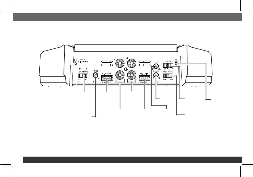
Controls, input connections and Indicators
GX-A604
|
|
|
|
|
|
|
|
|
|
|
|
|
|
|
|
|
|
|
|
|
|
|
|
|
|
|
|
|
|
|
|
|
|
|
|
|
|
|
|
|
|
|
|
|
|
Input |
|
|||
|
|
|
|
|
|
|
|
|
|
|
|
|||||
|
|
|
|
|
|
|
|
|
|
|
|
|||||
|
|
|
|
|
|
|
|
|
|
|
|
|||||
|
Power |
|
|
|
|
|
|
|
|
|
||||||
|
|
|
|
|
|
|
Mode |
|||||||||
|
Indicator |
|
|
|
|
|||||||||||
|
|
|
|
Switch |
||||||||||||
|
|
|
|
|
|
|
|
|
|
|
||||||
|
|
Front |
|
|
|
|
|
Front |
||||||||
|
Crossover |
|
|
|
|
|
|
|
Level |
|||||||
|
|
|
|
|
|
|
||||||||||
|
Filter Switch |
|
|
|
Control |
|||||||||||
Front |
Rear |
Rear |
Speaker-Level |
Line-Level |
Level |
Input |
Input |
Control |
Connector |
Connectors |
|
Front |
Rear |
Rear |
Line-Level |
Speaker-Level |
Crossover |
Input |
Input |
Control |
Connectors |
Connector |
|
Rear |
Protection |
Crossover |
|
Filter Switch |
Indicator |
Bass |
|
Boost |
|
Switch |
|
18

 English
GX-A602
|
L+L–R–R+ |
|
|
|
|
Line-level |
Speaker-Level |
Crossover |
Bass Boost |
Protection |
|
Input Connectors |
Input Connector |
Filter Switch |
Switch |
||
Indicator |
|||||
|
|
|
|
||
|
Level Control |
Power Indicator |
|
||
GX-A3001
L+L–R–R+ |
Line-Level |
Speaker-Level |
Level |
Crossover |
Bass Boost |
|
Protection |
Input Connectors |
Input Connector |
Control |
Control |
Control |
|
Indicator |
|
Power Indicator
www.jbl.com 19
set the crossover controls
GX-A604: 4-Channel Operation
Input Mode switch: Set the Input Mode switch in the "4CH" position.
Front Crossover Filter switch: Set the Front Crossover Filter switch in the "ON" (high-pass) position. This will limit the amount of low-frequency energy sent to the speakers, significantly reducing distortion and preventing the speakers from damage. Exception: If you have connected large full-range speakers (6" x 9" or larger) that can handle significant bass to the amplifier’s front channels and you are not using a subwoofer in the system, set the Front Crossover Filter switch to the "OFF" (full-range) position.
Rear Crossover Filter switch: Set the Rear Crossover Filter switch in the "HP" (high-pass) position. This will limit the amount of low-frequency energy sent to the speakers, significantly reducing distortion and preventing the speakers from damage. Exception: If you have connected large full-range speakers (6" x 9" or larger) that can handle significant bass to the amplifier’s front channels and you are not using a subwoofer in the system, set the Rear Crossover Filter switch to the "FLAT" (full-range) position.
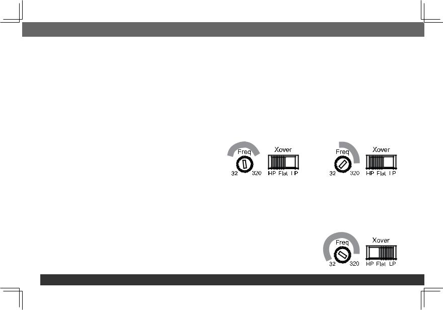
Rear Crossover control: When the Rear Crossover switch is set in |
6" and 5" Speakers |
4" and Smaller Speakers |
the "HP" position, the Rear Crossover control determines the frequency |
|
|
where the low frequencies sent to the speakers begin to be reduced in |
|
|
volume. |
|
|
When running the amplifier in the 4-channel mode you should set the |
|
|
Rear Crossover control according to the size of the speakers connected |
|
|
to the amplifier channels – the smaller the speakers the higher you |
|
|
need to set the control to protect the speakers from damage. After |
|
|
initially setting the crossover frequency, listen to music with strong bass |
|
|
that you are familiar with. If the speakers sound distorted or distressed, move the crossover frequency control to a higher setting to eliminate the distortion/ distress. The illustration to the right shows the recommended crossover filter frequency ranges for different speaker sizes.
GX-A604: 3-Channel Operation
Input Mode switch: Set the Input Mode switch in the "4CH" position.
Front Crossover switch: Set the Front Crossover switch in the "ON" (high-pass) position. This will limit the amount of low-frequency energy sent to the speakers, significantly reducing distortion and preventing the speakers from damage.
Rear Crossover Filter switch: When connecting a subwoofer or woofer to the rear channels, set the Rear Crossover Filter switch in the "LP" (low-pass) position. This will limit the amount of high-frequency energy sent to the woofers or subwoofer, improving the clarity of vocals and other midrange sounds.
Low-Pass Operation:
Subwoofers and Woofers
20
English
Rear Crossover control: The Rear Crossover control setting you use for subwoofers will depend on the type and location of your system’s subwoofer. Start by setting the Rear Crossover control to a frequency somewhat lower than the 80 Hz setting on the front channels. After listening to music on the system for a time, fine-tune the Rear Crossover control setting to achieve a smooth transition from the subwoofer to the rest of the system’s speakers while avoiding a "hole", where the sounds that occur between the subwoofer and other speakers seem to drop out. The illustration to the right shows the recommended Rear Crossover control frequency range.
GX-A604: 2-CHANNEL OPERATION
Input Mode switch: Set the Input Mode switch in the "2CH" position.
Front Crossover Filter switch: Set the Front Crossover Filter switch in the "ON" (high-pass) position. This will limit the amount of low-frequency energy sent to the speakers, significantly reducing distortion and preventing the speakers from damage. Exception: If you have connected large fullrange speakers (6" x 9" or larger) that can handle significant bass to the amplifier’s front channels and you are not using a subwoofer in the system, set the Front Crossover Filter switch to the "OFF" (full-range) position.
Rear Crossover Filter switch: Set the Rear Crossover Filter switch in the "HP" (high-pass) position. This will limit the amount of low-frequency energy sent to the speakers, significantly reducing distortion and preventing the speakers from damage. Exception: If you have connected large fullrange speakers (6" x 9" or larger) that can handle significant bass to the amplifier’s front channels and you are not using a subwoofer in the system, set the Rear Crossover Filter switch to the "FLAT" (full-range) position.
Rear Crossover control: When the Rear Crossover switch is set in |
6" and 5" Speakers |
4" and Smaller Speakers |
|
the "HP" position, the Rear Crossover control determines the frequency |
|||
|
|
||
where the low frequencies sent to the speakers begin to be reduced in |
|
|
|
volume. |
|
|
|
When running the amplifier in the 4-channel mode you should set the |
|
|
|
Rear Crossover control according to the size of the speakers connected |
|
|
|
to the amplifier channels – the smaller the speakers the higher you |
|
|
|
need to set the control to protect the speakers from damage. After |
|
|
|
initially setting the crossover frequency, listen to music with strong bass |
|
|
that you are familiar with. If the speakers sound distorted or distressed, move the crossover frequency control to a higher setting to eliminate the distortion/ distress. The illustration to the right shows the recommended crossover filter frequency ranges for different speaker sizes.
www.jbl.com 21
GX-A602: 2-Channel Operation
Crossover Filter switch:
•If you have connected the amplifier to a pair of 6" or smaller full-range speakers, set the Crossover Filter switch in the "HP" (high-pass) position.
This will limit the amount of low-frequency energy sent to the speakers, significantly reducing distortion and preventing the speakers from damage.
•If you have connected the amplifier to a pair of large full-range speakers (6" x 9" or larger) that can handle significant bass and you are not using a subwoofer in the system, set the Crossover Filter switch to the "FLAT" (full-range) position.
•If you have connected the amplifier to a pair of woofers or subwoofers, set the Crossover Filter switch in the "LP" (low-pass) position. This will limit the amount of high-frequency energy sent to the woofers/subwoofers, improving the clarity of vocals and other midrange sounds.
GX-A602: Bridged Operation
Crossover Filter switch: When operating the amplifier in bridged mode into a subwoofer, set the Crossover Filter switch in the "LP" (low-pass) position. This will limit the amount of high-frequency energy sent to the subwoofer.
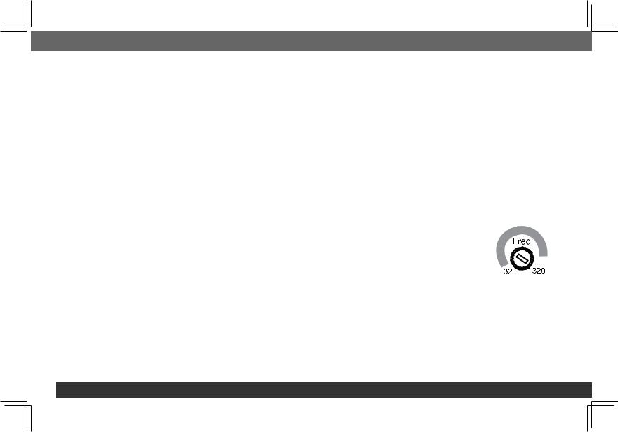
GX-A3001
NOTE: The GX-A3001’s internal crossover is permanently set for low-pass operation.
Crossover control: The Crossover control limits the amount of high-frequency energy sent to the woofers or subwoofer. The Crossover control setting you use for subwoofers will depend on the type and location of your system’s subwoofer. Start by setting the Crossover control to a frequency somewhat lower than the high-pass crossover setting you used for the system’s other speakers. After listening to music on the system for a time, fine-tune the Crossover control setting to achieve a smooth transition from the subwoofer to the rest of the system’s speakers while avoiding a "hole", where the sounds that occur between the subwoofer and other speakers seem to drop out. The illustration to the right shows the recommended
Crossover control frequency range.
Subwoofers
and Woofers
Set the Input level
1.Turn all the Level controls on all amplifiers fully counter-clockwise.
2.Play some dynamic music through your source unit and turn its volume up to 3/4 volume.
3.Slowly turn the Level control on the front-channel amplifier clockwise until the music begins to sound distorted.
4.Turn the Level control counter-clockwise slightly until the music no longer sounds distorted.
5.If you’re using more than one amplifier or are using the GX-A604, repeat Steps 3 – 4 for all remaining amplifier Level controls.
22
 English
SET THE BASS BOOST
GX-A604: When you’re using the amplifier’s rear channels to power a subwoofer, the Bass Boost switch can provide 12 dB of bass boost at 45 Hz.
(The switch only affects the amplifier’s rear channels.) Set this switch according to your personal taste, but if using it causes audible distortion or bottoming of your subwoofer we recommend setting it to "OFF". CAUTION: Only use the Bass Boost switch if you’ve configured the rear channels to power a subwoofer. Using the Bass Boost switch with full-range speakers can damage the speakers.
GX-A602: When you’re using the amplifier in bridged mode to power a subwoofer, the Bass Boost switch can provide 12 dB of bass boost at 45 Hz.
(Set this switch according to your personal taste, but if using it causes audible distortion or bottoming of your subwoofer we recommend setting it to "OFF". CAUTION: Only use the Bass Boost switch if you’re using the amplifier to power a subwoofer. Using the Bass Boost switch with full-range speakers can damage the speakers.
GX-A3001: The Bass Boost control can provide up to 12 dB of bass boost at 45 Hz. Set this control according to your personal taste, but be careful not to set the control at a high enough level to cause audible distortion or bottoming of your subwoofer.
POWER AND PROTECTION LEDS
POWER LED
•LED Illuminates orange: Normal operation (power is on).
•LED is off: Amplifier is in standby mode.
PROTECTION LED
The amplifier’s Protection LED should remain off during normal operation. If there is no sound from the amplifier and the Protection LED illuminates red, see Troubleshooting, on page 24.
www.jbl.com 23

TROUBLESHOOTING
If your amplifier isn’t performing the way you think is should, check to see if the problem is covered in this section before calling your dealer or contacting JBL customer service.
PROBLEM |
CAUSES AND SOLUTIONS |
|
|
No sound (the amplifier’s Power LED is off) |
• Check that the amplifier’s +12 V and GND connections have been properly made. |
|
• Check if the fuse on the +12 V wire located near the battery is blown: If so, replace it with an |
|
identical fuse. |
|
• Check all amplifier fuses; if any are blown, replace them with identical fuses. |
|
• If you are using the amplifier’s REM connection for turn-on, check that the wire is properly |
|
connected to the audio system’s remote turn-on wire or to the vehicle’s ACC power terminal. |
|
|
No sound (the amplifier’s Power LED is orange) • Check that all amplifier input and speaker connections have been properly made.
•Check that the amplifier’s Level controls are not turned all the way down (counter-clockwise).
•Check that the vehicle audio system’s source unit’s volume control is not turned all the way down.
No sound (the amplifier’s Protection LED is red) • Confirm that the vehicle’s electrical system is supplying between 9 V and 16 V DC to the amplifier. If the supply voltage is outside of this range, correct the condition before attempting to use the amplifier.
•If the amplifier has overheated, wait until it has cooled down before attempting to use it again.
•Disconnect all speakers from the amplifier and attempt to turn it on again:
–If the amplifier turns on (the Power LED is orange), there is a short circuit in one or more of the speaker wires. Correct all short circuits before reconnecting the speakers to the amplifier.
–If the amplifier does not turn on (the Protection LED is still red and the Power LED is off), contact your authorized JBL dealer for assistance.
24
 English
PROBLEM |
CAUSES AND SOLUTIONS |
Sound only comes from some of the speakers connected to the amplifier
•Check that the vehicle audio system’s source unit’s balance and fader controls are set to their center (midpoint) positions.
•(GX-A604): Check that the setting of the amplifier’s Mode Switch matches the input and speaker connections made to the amplifier
Sound is too quiet, even with the vehicle audio |
• Check that the amplifier’s Level controls are not turned too low. See Set The Input Level, on |
system’s source unit volume all the way up |
page 22, for information about setting the Level controls. |
|
|
Sound in the front/rear speakers is distorted |
• Make sure the amplifier’s Crossover Filter switch for the distorted channels is set to HP. |
|
• Set the Crossover control for the distorted channels to a higher setting. |
|
• Check that the distortion is not originating from the vehicle audio system’s source unit. |
|
|
Sound in the subwoofer is distorted |
• (GX-A604, GX-A602): Set the Bass Boost switch to "OFF". |
|
• (GX-A3001): While listening to bass-heavy music, turn the Bass Boost control all the way down, |
|
and then gradually increase it until the distortion begins to return. Reduce the Bass Boost |
|
control setting slightly to eliminate the distortion and leave it set there. |
|
• Check that the distortion is not originating from the vehicle audio system’s source unit. |
|
|
www.jbl.com 25
Specifications
|
GX-A604 |
GX-A602 |
GX-A3001 |
|||
|
|
|
|
|||
Max power (15.5 V, 1 kHz, 10% THD, |
435 W |
280 W |
415W (15.5 V, 50 Hz, 10% THD, |
|||
total ch, 2 ohms) |
|
|
|
|
2 ohms) |
|
Rated power output @ 4 ohms |
60 |
W x 4 |
60 |
W x 2 |
200 W x 1 |
|
|
|
|
|
|
|
|
Bridged power output |
170 W x 2 |
170 W x 1 |
N/A |
|||
(4 ohms, 1% THD) |
||||||
|
|
|
|
|
||
|
|
|
|
|||
THD+N at rated power |
<1% |
<1% |
<1% |
|||
|
|
|
|
|||
Signal-to-noise (2 V @ 4 ohms) |
>75 dB |
>75 dB |
>75 dB |
|||
|
|
|
|
|||
Effective damping factor (4 ohms) |
>50 |
>50 |
>50 |
|||
|
|
|
|
|
|
|
Frequency response (–3 dB) |
20 |
Hz – 20 kHz ±1 dB |
20 |
Hz – 20 kHz ±1 dB |
10 Hz – 320 Hz |
|
|
|
|
|
|
|
|
Maximum input voltage |
20 |
V |
20 |
V |
20 V |
|
|
|
|
|
|||
Maximum input sensitivity |
200 mV |
200 mV |
200 mV |
|||
|
|
|
|
|
|
|
Fuse size |
20 |
A x 2 |
25 |
A |
20 A x 2 |
|
|
|
|
|
|||
Dimensions (H x W x D) |
2-1/16" x 11-13/16" x 8-1/8" |
2-1/16" x 7-13/16" x 8-1/8" |
2-1/16" x 11-7/16" x 8-1/8" |
|||
(52 mm x 300 mm x 206 mm) |
(52 mm x 198 mm x 206 mm) |
(52 mm x 291 mm x 206 mm) |
||||
|
||||||
|
|
|
|
|||
Weight |
5.3 lb (2.4 kg) |
3.8 lb (1.7 kg) |
5.3 lb (2.4 kg) |
|||
|
|
|
|
|
|
|
26
GX-A604/GX-A602/GX-A3001
Verstärker
BEDIENUNGSANLEITUNG
Einleitung
VIELEN DANK für Ihren Kauf eines JBL®-Verstärkers der GX-Serie. Damit wir Sie im Falle einer Garantieleistung schneller bedienen können, bewahren Sie bitte den Original-Kaufbeleg auf und registrieren Sie Ihren Verstärker online unter www.jbl.com.
Mitgelieferte Bauteile

Verstärker der GX-Serie (x 1) |
Kabelbaum Lautsprecher-Pegeleingang |
|
(GX-A602, GX-A3001 x 1) (GX-A604 x 2) |
||
|
Aufstellung und Montage
Obwohl in dieser Anleitung die Installation der Verstärker der GX-Serie im Allgemeinen erklärt wird, werden keine spezifischen Installationsmethoden angegeben, die möglicherweise für Ihr Fahrzeug benötigt werden. Wenn Sie nicht über die notwendigen Werkzeuge oder die Erfahrung verfügen, versuchen Sie nicht, die Installation selbst durchzuführen. Fragen Sie dann bitte bei Ihrem autorisierten JBL-Fahrzeug-Audio-Händler nach einer professionellen Installation.
Warnungen und Tipps zur Installation
WICHTIG: Trennen Sie den Minus-(-)-Pol der Fahrzeugbatterie vor Beginn der Installation.
•Tragen Sie immer eine Schutzbrille, wenn Sie mit Werkzeugen arbeiten.
•Prüfen Sie die Abstände auf beiden Seiten einer geplanten Montagefläche. Achten Sie darauf, dass Schrauben oder Kabel keine Bremsleitungen, Kraftstoffleitungen oder Kabelbäume durchstechen und dass die Kabelführung nicht den sicheren Betrieb des Fahrzeugs beeinträchtigt.
•Achten Sie beim Herstellen von elektrischen Verbindungen darauf, dass diese sicher und korrekt isoliert sind.
•Wenn eine der Verstärker-Sicherungen ersetzt werden muss, achten Sie darauf, den gleichen Sicherungstyp und die korrekten Nennwerte wie beim Original zu verwenden.
2

 Deutsch
INSTALLATIONSORT
Verstärker benötigen eine Luftzirkulation, um kühl zu bleiben. Wählen Sie einen Ort an dem für den Verstärker ausreichend Luft für die Kühlung zur Verfügung steht.
•Geeignete Installationsorte befinden sich unter einem Sitz (sofern der Verstärker nicht mit der Sitzverstellung stört), im Kofferraum oder an einem anderen Ort, der ausreichend Kühlluft bietet.
•Montieren Sie den Verstärker nicht mit dem Kühlkörper nach unten, da dies die Konvektionskühlung des Verstärkers beeinträchtigt.
•Montieren Sie den Verstärker so, dass er nicht durch die Füße der Mitfahrer auf dem Rücksitz oder durch ein Verschieben der Ladung im Kofferraum beschädigt werden kann.
•Montieren Sie den Verstärker so, dass er trocken bleibt. Installieren Sie niemals einen Verstärker außerhalb des Autos oder im Motorraum.
MONTAGE DES VERSTÄRKERS
HINWEIS: Möglicherweise ist es bequemer, erst alle Anschlüsse am Verstärker herzustellen, bevor Sie ihn dauerhaft am Fahrzeug montieren.
1.Wählen Sie einen geeigneten Montageort, wie oben beschrieben.
2.Verwenden Sie den Verstärker als Schablone und markieren Sie die Positionen der Bohrungen auf der Montagefläche.
3.Bohren Sie Führungslöcher in die Montagefläche.
4.Befestigen Sie den Verstärker mit vier entsprechenden Befestigungsschrauben Ihrer Wahl an der Montagefläche. Wir empfehlen die Verwendung von M8 Kreuz-Blechschrauben. Stellen Sie sicher, der Verstärker sicher montiert ist.
www.jbl.com 3
Stromversorgungsund Erdungsanschlüsse
Wichtig: Trennen Sie den Minus-(-)-Pol der Fahrzeugbatterie vor Beginn der Installation.
Die Verstärker der GX-Serie können hohe Leistungspegel liefern und erfordern eine strapazierfähige und zuverlässige Verbindung mit dem elektrischen System des Fahrzeugs, um eine optimale Leistung zu erzielen. Beachten Sie bitte die folgenden Anweisungen sorgfältig.
Handhabung der Anschlüsse
Die Verstärker der GX-Serie verwenden die gleiche Art von Schraubanschlüssen für Strom und Lautsprecher. Dieser Anschlusstyp ist einfach zu handhaben und ermöglicht die einfache Verbindung von Kabeln mit großem Querschnitt.
Um die Anschlüsse zu verwenden, verwenden Sie einen Kreuzschlitz-Schraubendreher, um die Stellschraube des Anschlusses zu lösen. Führen Sie das blanke Kabel ein und ziehen Sie die Stellschraube fest, um das Kabel im zu sichern, wie in der Abbildung unten gezeigt.
Schraube |
Kabel unter |
Schraube |
lösen |
Scheibe legen |
festziehen |
WICHTIG: Achten Sie darauf, dass die nicht isolierten (+) und (-)-Lautsprecherkabel sich nicht gegenseitig und andere Anschlüsse am Verstärker und an den Lautsprechern berühren. Ein Berühren der nicht isolierten Kabel kann zu einem Kurzschluss und dadurch zu Schäden am Verstärker
führen.
4
 Loading...