


EON610
User’s Guide
EON 618S

2

3
CONTENTS
Safety Instructions .....................................................................................................................................4
Declaration Of Conformity ......................................................................................................................... 5
Quick Setup Guide ......................................................................................................................................6
Back Panel ..................................................................................................................................................8
Overview - EON Family .............................................................................................................................10
EON Family - Block Diagram ....................................................................................................................11
EON615 Specifications ............................................................................................................................13
EON612 Specifications ............................................................................................................................14
EON610 Specifications ............................................................................................................................15
EON618S Specifications ..........................................................................................................................16
Purposeful Product Design.......................................................................................................................17
Coverage .................................................................................................................................................. 18
Bluetooth Integration ................................................................................................................................19
Loudspeaker Placement and Suspension ...............................................................................................20
Application Examples .............................................................................................................................. 21
Trouble Shooting ....................................................................................................................................... 24
Warranty Information .............................................................................................................................. 25
Contact Information ................................................................................................................................. 26

4
Before You Begin - Important Information
Before using your EON® speaker system please review the following for important
information on safety and protection of your investment in quality loudspeakers.
1. Read these instructions.
2. Keep these instructions.
3. Heed all warnings.
4. Follow all instructions.
5. Do not use this apparatus near water.
6. Clean only with dry cloth.
7. Do not block any ventilation openings. Install in accordance with the manufacturer’s instructions.
8. Do not install near any heat sources such as radiators, heat registers, stoves, or other apparatus
(including amplifiers) that produce heat.
9. Do not defeat the safety purpose of the polarized or grounding-type plug. A polarized plug has two blades with one wider than
the other. A grounding-type plug has two blades and a third grounding prong. The wide blade or the third prong is provided
for your safety. If the provided plug does not fit into your outlet, consult an electrician for replacement of the obsolete outlet.
10. Protect the power cord from being walked on or pinched, particularly at plugs, convenience receptacles, and the point where
they exit from the apparatus.
11. Only use attachments/accessories specified by the manufacturer.
12. Use only with the cart, stand, tripod, bracket, or table specified by the manufacturer, or sold with the
apparatus. When a cart is used, use caution when moving the cart/apparatus combination to avoid injury
from tip-over.
13. Unplug this apparatus during lightning storms or when unused for long periods of time.
14. Refer all servicing to qualified service personnel. Servicing is required when the apparatus has been
damaged in any way, such as power supply cord or plug is damaged, liquid has been spilled or objects
have fallen into the apparatus, the apparatus has been exposed to rain or moisture, does not operate normally,
or has been dropped.
15. Service Instruction in Owner’s Manual: “CAUTION - THESE SERVICING INSTRUCTIONS ARE FOR USE BY QUALIFIED SERVICE
PERSONNEL ONLY. TO REDUCE THE RISK OF ELECTRIC SHOCK DO NOT PERFORM ANY SERVICING OTHER THAN THAT
CONTAINED IN THE OPERATING INSTRUCTIONS UNLESS YOU ARE QUALIFIED TO DO SO.”
16. To completely disconnect this apparatus from the AC mains, disconnect the power supply cord plug from
the AC receptacle.
17. “WARNING – TO REDUCE THE RISK OF FIRE OR ELECTRIC – SHOCK, DO NOT EXPOSE THIS APPARATUS TO RAIN
OR MOISTURE.”
18. Do not expose this equipment to dripping or splashing and ensure that no objects filled with liquids, such as vases, are
placed on the equipment.
19. The mains plug of the power supply cord shall remain readily operable.
SAFETY INSTRUCTIONS

5
DECLARATION OF CONFORMITY
Safety And EMC Compliance Specifications
EN 55103-1:1997 Electromagnetic Compatibility - Product Family Standard for Audio, Video, Audio-Visual and Entertainment Lighting Control
Apparatus for Professional Use, Part 1: Emissions
EN 55103-1:1997 Magnetic Field Emissions-Annex A@ 10 cm and 20 cm
EN 55022:2003 Limits and Methods of Measurement of Radio Disturbance Characteristics of ITE: Radiated, Class B Limits; Conducted, Class A
EN 55103-2:1997 Electromagnetic Compatibility - Product Family Standard for Audio, Video, Audio-Visual and Entertainment Lighting Control
Apparatus for Professional Use, Part 2: Immunity
EN 61000-4-2: A2:2001 Electrostatic Discharge Immunity (Environment E2-criteria B, 4 kV Contact, 8 kV Air discharge)
EN 61000-4-3:2003 Radiated, Radio-frequency, Electromagnetic Immunity (Environment E2, criteria A)
EN61000-4-4:2005 Electrical Fast Transient/Burst Immunity (criteria B)
EN 61000-4-5:2001 Surge Immunity (criteria B)
EN 61000-4-6:1996 Immunity to Conducted Disturbances Induced by Radio-Frequency Fields (criteria A)
EN 61000-4-11:2004 Voltage Dips, Short Interruptions and Voltage Variation
UL 6500 2nd Edition 1999 Audio/Video and Musical Instruments Apparatus for Household, Commercial, and Similar General Use
IEC 60065_2001 / EN 60065_2002 + A1:2006 + A11:2008
UL Compliance Specifications
UL 60065 7th Ed. CAN/CSA 22.2 No.60065_2003
FCC Statement IC Warning
1. This device complies with Part 15 of the FCC Rules.
Operation is subject to the following two conditions:
(1) This device may not cause harmful interference.
(2) This device must accept any interference received,
including interference that may cause undesired operation.
2. Changes or modifications not expressly approved by the party
responsible for compliance could void the user’s authority to
operate the equipment.
NOTE: This equipment has been tested and found to comply
with the limits for a Class B digital device, pursuant to Part 15 of
the FCC Rules. These limits are designed to provide reasonable
protection against harmful interference in a residential installation.
This equipment generates uses and can radiate radio frequency
energy and, if not installed and used in accordance with
the instructions, may cause harmful interference to radio
communications. However, there is no guarantee that interference
will not occur in a particular installation. If this equipment does
cause harmful interference to radio or television reception, which
can be determined by turning the equipment off and on, the user is
encouraged to try to correct the interference by one or more of the
following measures:
• Reorient or relocate the receiving antenna.
• Increase the separation between the equipment and receiver.
• Connect the equipment into an outlet on a circuit different from
that to which the receiver is connected.
• Consult the dealer or an experienced radio/TV technician for help.
FCC Radiation Exposure Statement
This equipment complies with FCC radiation exposure limits set forth for
an uncontrolled environment. This equipment should be installed and
operated with minimum distance 20cm between the radiator & your body
1. This device complies with Industry Canada’s license-exempt RSSs.
Operation is subject to the following two conditions:
(1) this device may not cause interference, and
(2) this device must accept any interference, including interference
that may cause undesired operation of the device.
2. Changes or modifications not expressly approved by the party
responsible for compliance could void the user’s authority to operate
the equipment.
Le présent appareil est conforme aux CNR d’Industrie Canada applicables
aux appareils radio exempts de licence. L’exploitation est autorisée aux
deux conditions suivantes :
(1) l’appareil ne doit pas produire de brouillage, et
(2) l’utilisateur de l’appareil doit accepter tout brouillage
radioélectrique subi, même si le brouillage est susceptible d’en
compromettre le fonctionnement.”
6
QUICK SETUP GUIDE
Congratulations on your purchase of JBL Professional EON600 Series loudspeakers! We know you are anxious to get up and
running as fast as possible, which is why you are reading this section. The following will help you get set up as soon as possible.
Packaging Contents
Your EON600 system should include the following:
1 x EON600 speaker
1 x 10'(3m) IEC Power Cable
1 x Quick Start Guide
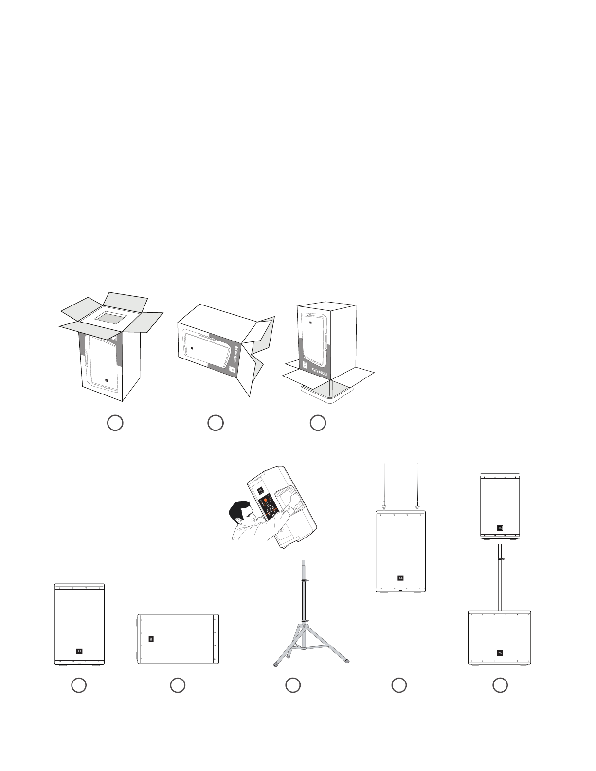
Unbox it
Open the top of the box. Turn box upside down, then lift box up to reveal speaker.Lay box on its side.
Configuration Options
Floor Standing Monitor Position Pole Mounted Suspended Subwoofer Mounted
1
1
2
2
3 4 5
3
7
GAIN
LIMITSIGNAL SIGNAL
GAIN
MAIN
IN 1
MONITOR
SUB
BLUETOOTH
MASTER
VOLUME
MIC
LINE
IN 2
THRU
EQ +
EQ
PRESETS
BOOT
SPEECH
SYNC
FRONT LED
POWER
ON OFF
MIC
LINE
EON 615
CH1 CH2
THIS DEVICE COMPLIES WITH PART 15 OF THE FCC RULES.
OPERATION IS SUBJECT TO THE FOLLOWING TWO CONDITIONS:
(1) THIS DEVICE MAY NOT CAUSE HARMFUL INTERFERENCE.
(2) THIS DEVICE MUST ACCEPT ANY INTERFERENCE THAT MAY CAUSE UNDESIRED OPERATION.
FUSE TYPE: T3.15L250V
FOR CONTINUED PROTECTION AGAINST RISK OF FIRE, REPLACE FUSE ONLY WITH SAME TYPE OF RATING.
430W Max
100-120VAC 50/60Hz
230-240VAC 50/60Hz
MODEL: EON615
SERIAL NO:
JBL PROFESSIONAL
NORTHRIDGE, CA. USA
A HARMAN INTERNATIONAL COM PANY
DESIGNED AND ENGINEERED IN THE USA
Made in
Mexico
A
B
E
F
K
M
N
O
D
G
H
L
I
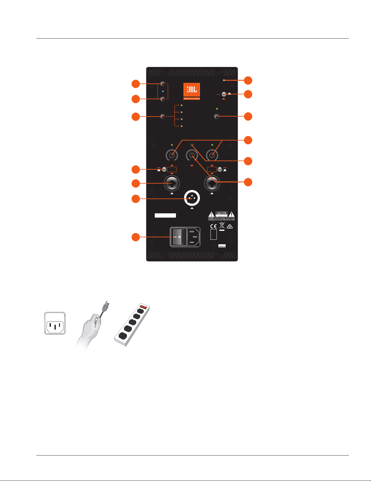
Power LED
Bluetooth Sync
Bluetooth Boot
EQ Presets
Mic/Line Button
XLR-1/4” Combo Inputs
XLR Male Loop Thru
Power Switch
Front LED On/Off
EQ+ On/Off
CH1 & CH2 Gain
Master Volume
Limit LED
SET OUTPUT LEVEL
1. Using the EQ Preset ( F ) button, select the
appropriate preset to match your application ( Full-
Range Only ).
2. Set the gain level for the input using the Channel
Gain ( H ) controls. A good starting point is to set
the pot at 12 o’clock.
3. Slowly turn Master Volume ( L ) to the right until
the desired volume is reached.
POWER IT ON
1. Confirm the Power Switch ( O ) is in the OFF position.
2. Connect the supplied power cord to the power receptacle
on the rear of the speaker.
3. Connect the power cord to an available power outlet.
4. Flip on the Power Switch ( O ) and the Power LED ( A ) and
the Power LED on the front of the speaker will illuminate.
PLUG IN THE INPUTS
1. Turn Channel Gain Controls ( H ) and Master
Volume Control ( L ) all the way to the left before
connecting any inputs
2. Connect XLR or TRS cable from audio source to
CH1 or CH2 inputs ( M )
3. Select Mic or Line via the Mic/Line Button ( K;
Full-Range Only )
QUICK SETUP GUIDE
8
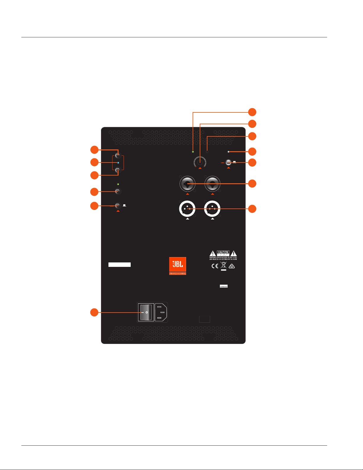
SUBWOOFER BACK PANEL
LIMITSIGNAL
IN 1
BLUETOOTH
MASTER VOLUME
IN 2
EQ +
BOOT
SYNC
POLARITY
POWER
0
º
180
º
FRONT LED
ON OFF
THRU 1 THRU 2
THIS DEVICE COMPLIES WITH PART 15 OF THE FCC RULES.
OPERATION IS SUBJECT TO THE FOLLOWING TWO CONDITIONS:
(1) THIS DEVICE MAY NOT CAUSE HARMFUL INTERFERENCE.
(2) THIS DEVICE MUST ACCEPT ANY INTERFERENCE THAT MAY CAUSE UNDESIRED OPERATION.
FUSE TYPE: T3.15L250V
FOR CONTINUED PROTECTION AGAINST RISK OF FIRE, REPLACE FUSE ONLY WITH SAME TYPE OF RATING.
430W Max
100-120VAC 50/60Hz
230-240VAC 50/60Hz
MODEL: EON618S
SERIAL NO:
JBL PROFESSIONAL
NORTHRIDGE, CA. USA
A HARMAN INTERNATIONAL COMPANY
DESIGNED AND ENGINEERED IN THE USA
Made in
China
EON 618S
J
B
E
C
G
P
M
N
O
D
L
I
A
Signal Indicator
Bluetooth Sync
Bluetooth Boot
Bluetooth Indicator
EQ+ On/Off
Polarity Switch
XLR-1/4”Combo Inputs
XLR Male Loop Thru
Power Switch
Front LED On/Off
Master Volume
Limit LED
Power LED

9
BACK PANEL
A. Power LED
This LED (White) lights to indicate that the speaker is plugged in and
switched ON.
B. Bluetooth Sync
Depress this button in order to initiate pairing with your
Bluetooth enable device.
C. Bluetooth Indicator
This LED will illuminate blue to indicate that your Bluetooth
connection is established.
D. Front LED On/Off
Toggles the LED (Blue) on front of speaker On or Off.
E. Bluetooth Boot
Depress this button to reset the pairing with your Bluetooth enabled device
without having to turn the speaker off.
F. EQ Presets (Full-Range Only)
Use this button to toggle through the four different settings.
MAIN:
This is the default setting for the EON600 loudspeakers. Use this
setting when your EON600 loudspeaker is being used either on a
tripod or pole and facing towards your audience.
MONITOR:
Use this setting when your EON600 loudspeaker is being used as a
stage monitor facing towards you.
SUB:
Use this setting when your EON600 loudspeaker is being used in
conjunction with a separate subwoofer. This preset enables a High
Pass Filter (HPF) set at 100Hz.
SPEECH:
Use this setting when your EON600 loudspeaker is being used for
Speech only or Spoken Word only applications and is facing towards
the audience.
G. EQ+ Button
Once enabled via the app, the EQ+ toggles the applied EQ settings on/off.
H. CH1 & CH2 Gain (Full-Range Only)
Controls the gain of CH1 & CH2 respectively. By turning the signal counter-
clockwise you will be lowering the gain of your source material. By turning
the control clockwise you will be increasing the gain.
I.
Limit Indicator
The LIMIT LED (Red) illuminates to indicate that the system is approaching
limit. If this LED is on for more than the duration of brief dynamic peaks,
the system is being over-driven. Continuously over-driving the system will
result in unpleasant and fatiguing distortion and may lead to premature
failure of your speaker system.
J. Signal Indicators
The SIGNAL LEDs (Green) illuminates to indicate a usable signal is
present at connected INPUTS.
K. Mic/Line Toggle (Full-Range Only)
The MIC/LINE buttons selects between two sensitivity ranges. The buttons
are used to match the input sensitivity with the output level of the devices
connected to CH1 or CH2. Depressing the MIC/LINE switch selects
MIC (High Sensitivity).
CAUTION: Before adjusting this switch, be certain to rotate the control fully counter-clockwise.
After the MIC/LINE switch has been depressed, slowly rotate the control clock-wise until the
desired volume has been reached.
• Use the MIC position (depressed) when a microphone is
connected.
• Use the LINE position (disengaged) when a line level source
such as an audio mixing console, audio playback device or
electronic musical instrument is connected.
L. Master Volume
Controls the master volume of the unit. By turning the knob counter-
clockwise you will be lowering the overall volume of the speaker. By turning
the control clockwise you will be increasing the overall volume of the
speaker.
M. XLR-1/4” Combo Inputs
These balanced inputs accepts a standard XLR (female) connector and
also a 1/4” TRS phone plug. A broad range of signals from microphones,
audio mixing consoles and electronic musical instruments may be
connected here. The sensitivity of these inputs are controlled by the MIC/
LINE SWITCHES.
N. XLR Male Loop Thru
This XLR (male) output connector provides a method of sending audio
out to an external source. If signal is present on both inputs, the inputs will
be summed and sent out as a 50/50 mix
O. Power Switch
Enables the AC power to the unit on and off.
P. Polarity Switch (Subwoofer Only)
Switches the polarity of the subwoofer between 0 and 180 degrees. Useful
for correcting summing issues between the subwoofer and the top boxes.
Users should experiment with the switch at both positions and select the
best sounding option for their specific application.
 Loading...