


CONTROL 26CT
Control Contractor
Ceiling Loudspeakers
Owner’s Manual

1
Table of Contents
Product Description.........................................................................................2
Product Feature Identification.........................................................................3
Installation Preparations.................................................................................. 4
Step-By-Step Installation and Wiring.............................................................6
Painting the Speaker...................................................................................... 15
Safety Agency Compliance...........................................................................16
Maintenance.................................................................................................. 16
Replacement Parts.........................................................................................17
Contacting JBL.............................................................................................. 17

2
Thank you for purchasing JBL Control Contractor ceiling loudspeakers.
Read through this manual to familiarize yourself with the features, applications and
precautions before you use these products.
Product Descriptions
The JBL Control Contractor ceiling loudspeakers utilize innovative design and
materials to provide premium level performance from compact in-ceiling speakers.
CONTROL 24C & 24CT
– Most compact of the JBL ceiling speakers, the Control
24C contains a coaxially mounted 4” woofer and ¾” titanium-coated tweeter,
providing high-fidelity full-range sound over an extremely wide coverage area. The
optional Control 24C
T
includes a multi-tap transformer for 70V or 100V systems.
CONTROL 26C & 26CT
– The Control 26C is a powerhouse ceiling speaker
containing a coaxially mounted 6.5” woofer and ¾” titanium-coated tweeter, able to
deliver maximum sound level over a wide coverage area. The optional Control 26C
T
includes a multitap transformer for a 70V or 100V line distribution system.
CONTROL 19CS & 19CST Subwoofer
– The unique Nested Chamber design and
Linear Dynamics port allows powerful low-frequency reinforcement from a
compact in-ceiling enclosure. The Control 19CS is an ideal addition to any system,
resulting in full-fidelity high level sound. The optional Control 19CS
T
includes a
special subwoofer-band transformer for use on 70V or 100V line distribution systems.
3
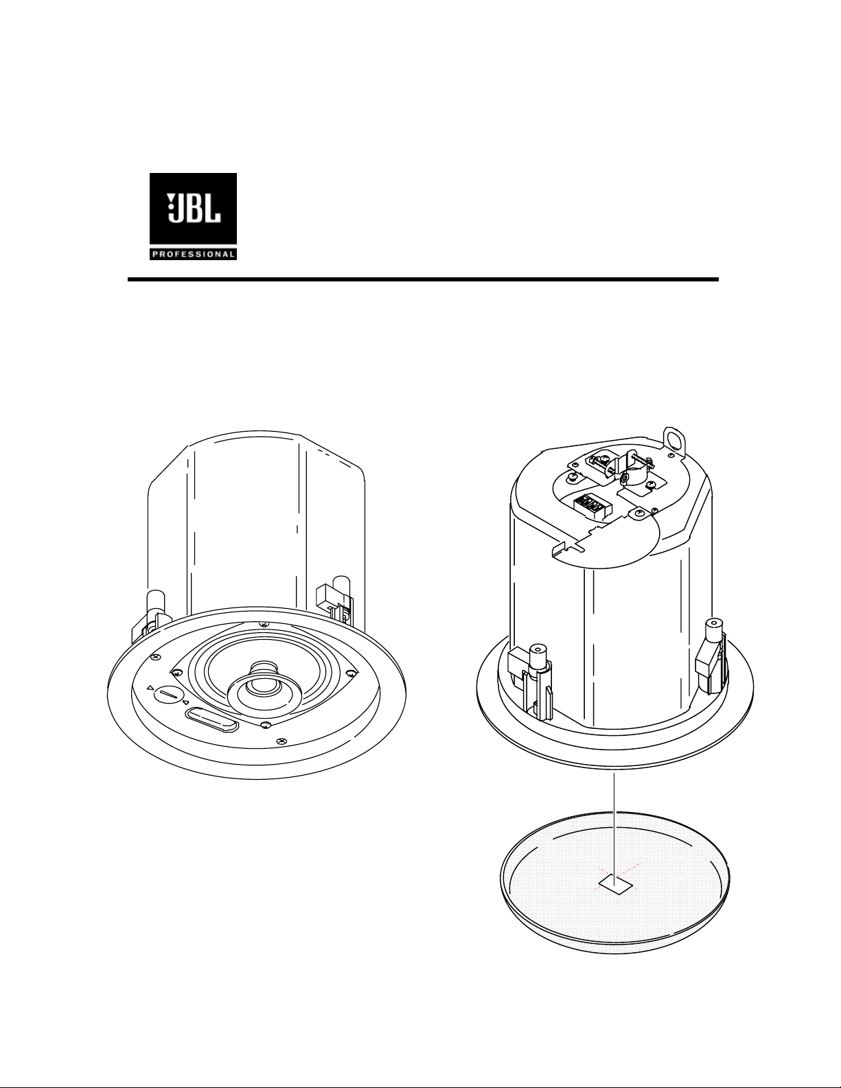
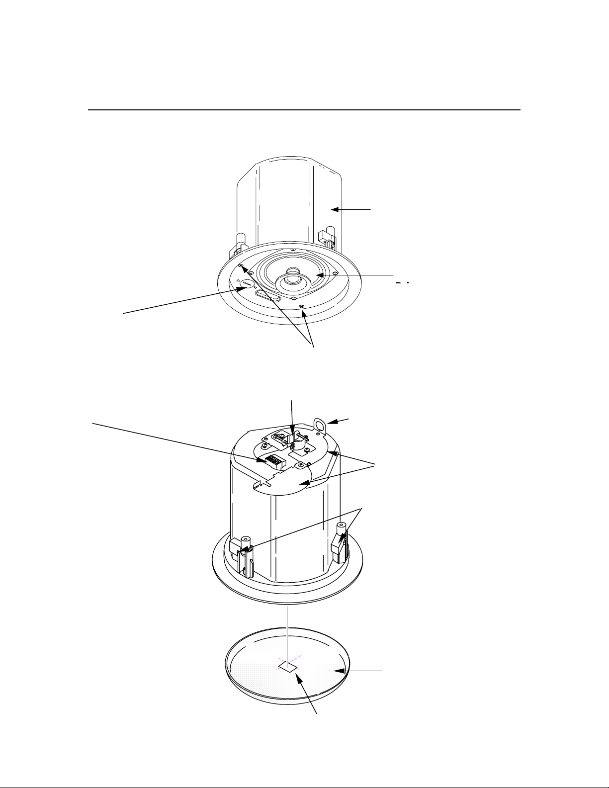
Product Feature Identification
Attachment Screws
Tap Selector (on T-versions)
Loudspeaker
Seismic Tab
(secondary support point)
-
Steel Backcan
Rotating Mounting Tabs
JBL Logo
Removable Lockin
g
In
p
ut Connector
Strain Relief Fitting
Terminal Cover Plate Assembly
(
Control 24C Shown)

4
Installation Preparations
The entire installation can be accomplished, if necessary, without requiring access
above the ceiling. Bracketry for use with either suspended ceilings or sheetrock
ceilings is included. The speaker is held securely in place via mounting ears which
lock into place. Inputs are attached to a removable locking connector (included)
which can be prewired before installing the speaker for ultra-fast snap-on installation.
OPTIONAL PRE-INSTALLATION BRACKETS
IN MOST CASES, NO BRACKETS OTHER THAN THE ONES INCLUDED WITH
YOUR SPEAKER ARE REQUIRED. Everything needed for most installations of
these loudspeakers is provided with your Control Contractor ceiling speaker.
However, a particular procedure that is sometimes used for installation into sheet rock
(typically gypsum board) can be facilitated by the use of JBL’s optional preinstallation
brackets before the sheetrock is installed. The preinstallation bracket provides a
bracket to which wiring can be tied behind the sheetrock and it can function as a
cutout template when many cutouts are to be made in a production-line style
installation. Two types of pre-installation brackets are available from JBL
Professional as optional accessories:
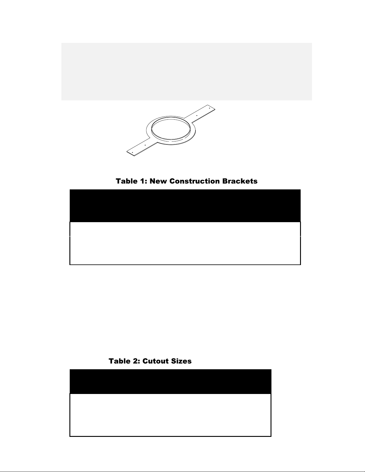
1) The optional
NEW-CONSTRUCTION BRACKET
is made of flat sheetmetal,
with wings to attach to the building structure. Holes are drilled for nails or screws at
16 inches (406 mm) and 24 inches (610 mm) on-center. Additional holes can be
drilled by the installer at other spacings up to a maximum of 24-3/4 inches (630 mm)
apart. Sheet rock installs over the bracket, and the bracket provides a template for
blind cutout of the hole in the sheet rock. The sheet rock is typically cut with a router-
type cutting tool, using the bracket ring as a cutout guide.
Figure 1:
Optional New -Construction Bracket
5
2) The optional
PLASTER-RING BRACKET
(or “mud ring”) contains a circular
offset, forming a edge guide for sheet rock plastering. The bracket has wings that
attach to the building structure. Sheet rock is typically either precut or cut with a
rotary cutting tool using the outside of the plaster ring circle as a guide. The sheet
rock hole is then plastered (or “mudded”) up to the ring to create a seamless cutout.
Mod el
New
Con structio n
Bra cket
Pla ster- Rin g
Bra cket
Control 24C & 24CT MTC-24NC MTC-24MR
Control 26C & 26CT MTC-26NC MTC-26MR
Control 19CS & 19CST MTC-19NC MTC-19MR
USING INCLUDED C-BRACKET WITH SHEETROCK
For most installations, the INCLUDED C-shaped backing plate to provides adequate
reinforcement to the ceiling material, spreading out the clamping force from the tab
clamps.
CUTOUT SIZES
Packaged with the speakers are cardboard cutout templates for scribing the cutout hole
onto your ceiling surface.
Mod el Cut out S ize
(di amet er)
Control 24C & 24CT 168 mm (6.6 in)
Control 26C & 26CT 220 mm (8.75 in)
Control 19CS & 19CST 305 mm (12.0 in)
Figure 2:
Optional Plaster Ring Bracket
 Loading...