


FlexaTwin
• Manuale d’installazione
CONSERVARE CON CURA
• Installation manual
KEEP CAREFULLY
• Notice d’installation
GARDEZ SOIGNEUSEMENT
• Installations Anweisung
SORGFÄLTIG AUFBEWAHREN
• Manual de instalación
CONSERVAR CON CUIDADO
• Manual de instalação
CONSERVAR COM CUIDADO
1 |
2 |
3 |
DISEGNI ALL’INTERNO • DRAWINGS INSIDE
DESSINS A L’INTERIEUR • ZEICHNUNGEN INNEN
DIBUJOS EN EL INTERIOR • DESENHOS EM ANEXO

FlexaTwin
• CARATTERISTICHE TECNICHE . . . . . . . . . . . . . . . . . |
4 |
• TECHNICAL CHARACTERISTICS . . . . . . . . . . . . . . . 4
• CARACTERISTIQUES TECHNIQUES . . . . . . . . . . . . 4
• TECHNISCHE ANGABEN . . . . . . . . . . . . . . . . . . . . . . 5
• CARACTERÍSTICAS TÉCNICAS . . . . . . . . . . . . . . . . . . 5
• CARACTERÍSTICAS TÉCNICAS . . . . . . . . . . . . . . . . . . 5
• Italiano . . . . . . . . . . . . . . . . . . . . . . . . . . . . . . . . . . . . . 6
• English . . . . . . . . . . . . . . . . . . . . . . . . . . . . . . . . . . . . 11
• Français . . . . . . . . . . . . . . . . . . . . . . . . . . . . . . . . . . . 16
• Deutsch . . . . . . . . . . . . . . . . . . . . . . . . . . . . . . . . . . . 21
• Español . . . . . . . . . . . . . . . . . . . . . . . . . . . . . . . . . . . 49
• Português . . . . . . . . . . . . . . . . . . . . . . . . . . . . . . . . . 54
ITALIANO |
|
CARATTERISTICHE TECNICHE |
|
|
|
(j) potenza assorbita (max. 2,5 kW) |
|||||||||
|
|
|
|
(k) a 230V |
|
||||||||||
|
|
|
|
|
|
||||||||||
|
|
|
|
|
|
|
|
|
|
|
|
|
|
||
|
Modello |
Alimentazione |
|
Ampére |
|
Ampére |
kW/HP |
|
kW |
(*) 21 psi min - 70 psi max |
|||||
|
|
(pompa) |
(bagno turco) |
(pompa) |
|
(bagno turco) |
|||||||||
|
|
|
|
|
|
|
|||||||||
|
|
|
|
|
|
|
|
|
|
|
|
|
(x) vasca: 4+6 |
|
|
|
|
Hz |
|
Volt |
|
A |
|
A |
kW/HP |
|
kW |
|
|||
|
|
|
|
|
|
(y) idrogetti (a 2,5 bar) |
|
||||||||
|
|
|
|
|
|
|
|
|
|
|
|
|
|
||
|
ST2 |
50 |
220/240 |
|
6(18) |
|
- |
|
1,2 (j)/1,2 |
|
- |
|
|||
|
|
|
|
|
(z) rotodoccia (a 2,5 bar) |
|
|||||||||
|
|
|
|
|
|
|
|
|
|
|
|
|
|
||
|
ELT10 - ELT11 |
50 |
220/240 |
|
6(18) |
|
11 (k) |
1,2 (j)/1,2 |
|
2,5 (j) (k) |
|
||||
|
|
|
|
|
|
|
|||||||||
|
|
|
|
|
|
|
|
|
|
|
|
||||
|
|
|
|
|
CARATTERISTICHE IDRAULICHE |
|
|
|
|||||||
|
|
|
|
|
|
|
|
|
|
|
|
|
|
|
|
|
Modello |
Pressione |
|
Pressione |
|
Bocchette |
|
Consumo d'acqua |
Collegamenti |
||||||
|
di esercizio |
|
ottimale |
|
idromassaggio |
|
max. |
|
|||||||
|
|
|
|
|
|
|
|
||||||||
|
|
Bar (*) |
|
Bar |
|
|
N° |
|
l/min |
|
H2O calda/fredda |
Piletta di scarico |
|||
|
ST2 |
1,5 min |
|
5 max |
|
2 3 |
|
16 + 8 (x) |
|
12 (y) |
|
1/2" |
1 1/2" |
||
|
ELT10 - ELT11 |
1,5 min |
|
5 max |
|
2 3 |
|
16 + 8 (x) |
|
11 (z) |
|
1/2" |
1 1/2" |
||
ENGLISH |
|
TECHNICAL CHARACTERISTICS |
|
|
|
|
(j) power absorption (max. 2.5 kW) |
||||||||||
|
|
|
|
|
(y) hydronozzles (at 2,5 bar) |
|
|||||||||||
|
|
|
|
|
|
|
|
|
|
|
|
|
|
(k) at 230V |
|
||
|
Model |
Power supply |
|
Ampére |
|
Ampére |
kW/HP |
|
kW |
|
(*) 21 psi min - 70 psi max |
|
|||||
|
|
(pump) |
(steam bath) |
(pump) |
|
(steam bath) |
|
|
|||||||||
|
|
|
|
|
|
|
|
|
|
|
|
|
|
(x) tub: 4+6 |
|
||
|
|
Hz |
|
Volt |
|
A |
|
A |
kW/HP |
|
kW |
|
|
||||
|
|
|
|
|
|
|
|
|
|
|
|||||||
|
|
|
|
|
|
|
|
|
|
|
|
|
|
|
|
|
|
|
ST2 |
50 |
220/240 |
|
6(18) |
|
- |
|
1,2 (j)/1,2 |
|
- |
|
(z) rotoshower (at 2,5 bar) |
|
|||
|
|
|
|
|
|
|
|
|
|
|
|
|
|
|
|||
|
ELT10 - ELT11 |
50 |
220/240 |
|
6(18) |
|
11 (k) |
1,2 (j)/1,2 |
|
2,5 (j) (k) |
|
|
|||||
|
|
|
|
|
|
|
|
|
|||||||||
|
|
|
|
|
|
|
|
|
|
|
|
|
|
||||
|
|
|
|
|
HYDRAULIC CHARACTERISTICS |
|
|
|
|
||||||||
|
|
|
|
|
|
|
|
|
|
|
|
|
|
|
|
|
|
|
Model |
Operating |
|
Optimum |
|
Hydromassage |
|
Max. water |
|
Connections |
|||||||
|
pressure |
|
pressure |
|
nozzles |
|
consumption |
||||||||||
|
|
|
|
|
|
|
|
||||||||||
|
|
Bar (*) |
|
Bar |
|
|
N° |
|
l/min |
|
Hot/cold water |
|
Drain |
||||
|
|
|
|
|
|
|
|
|
|
|
|
|
|
|
|
|
|
|
ST2 |
1,5 min |
|
5 max |
|
2 3 |
|
16 + 8 (x) |
|
12 (y) |
|
1/2" |
|
1 1/2" |
|||
|
ELT10 - ELT11 |
1,5 min |
|
5 max |
|
2 3 |
|
16 + 8 (x) |
|
11 (z) |
|
1/2" |
|
1 1/2" |
|||
FRANÇAIS
|
CARACTERISTIQUES TECHNIQUES |
|
|
(j) puissance absorbée (max. 2,5 kW) |
|||||
|
|
|
(k) à 230V |
||||||
|
|
|
|
|
|
|
|
|
|
Modèle |
|
Alimentation |
Ampére |
Ampére |
|
kW/HP |
kW |
(*) 21 psi min - 70 psi max |
|
|
(pompe) |
(bain turc) |
|
(pompe) |
(bain turc) |
||||
|
|
|
|
|
|||||
|
|
|
|
|
|
|
|
|
(x) baignoire: 4+6 |
|
|
Hz |
Volt |
A |
A |
|
kW/HP |
kW |
|
|
|
|
(y) buses hydro vertical (à 2,5 bar) |
||||||
|
|
|
|
|
|
|
|
|
|
ST2 |
|
50 |
220/240 |
6(18) |
- |
|
1,2 (j)/1,2 |
- |
|
|
|
(z) douche tournant (à 2,5 bar) |
|||||||
|
|
|
|
|
|
|
|
|
|
ELT10 - ELT11 |
|
50 |
220/240 |
6(18) |
11 (k) |
|
1,2 (j)/1,2 |
2,5 (j) (k) |
|
|
|
|
|||||||
CARACTERISTIQUES HYDRAULIQUES
Modèle |
Pression |
Pression |
Buses |
Consommation |
Raccordements |
|||
de service |
optimal |
hydromassage |
d'eau |
|||||
|
|
|
||||||
|
Bar (*) |
Bar |
N° |
l/min |
H2O chaude/froide |
Vidage |
||
ST2 |
1,5 min |
5 max |
2 3 |
16 + 8 (x) |
12 (y) |
1/2" |
1 1/2" |
|
ELT10 - ELT11 |
1,5 min |
5 max |
2 3 |
16 + 8 (x) |
11 (z) |
1/2" |
1 1/2" |
|
4
|
|
|
|
|
|
|
|
|
|
|
|
(j) Leistungsaufnahme (max.2,5 kW) |
DEUTSCH |
||||
|
TECHNISCHE ANGABEN |
|
|
|
|
||||||||||||
|
|
|
|
(k) hat 230V |
|
|
|
|
|||||||||
|
|
|
|
|
|
|
|
|
|
|
|
|
|
|
|
||
Modell |
Netzanschluß |
Ampére |
|
Ampére |
kW/HP |
|
kW |
(*) 21 psi min - 70 psi max |
|
|
|||||||
(Pumpe) |
(Dampfbad) |
(Pumpe) |
|
(Dampfbad) |
|
|
|||||||||||
|
|
|
|
|
|
|
|
||||||||||
|
|
|
|
|
|
|
|
|
|
|
|
(x) Wanne: 4+6 |
|
|
|
|
|
|
Hz |
|
Volt |
A |
|
A |
kW/HP |
|
kW |
|
|
|
|
||||
|
|
|
|
(y) Massagedüsen (hat 2,5 bar) |
|
||||||||||||
|
|
|
|
|
|
|
|
|
|
|
|
|
|||||
ST2 |
50 |
220/240 |
|
6(18) |
|
- |
|
1,2 (j)/1,2 |
|
- |
|
||||||
|
|
|
|
(z) Rotordusche (hat 2,5 bar) |
|
|
|||||||||||
|
|
|
|
|
|
|
|
|
|
|
|
|
|
||||
ELT10 - ELT11 |
50 |
220/240 |
|
6(18) |
|
11 (k) |
1,2 (j)/1,2 |
|
2,5 (j) (k) |
|
|
||||||
|
|
|
|
|
|
|
|
|
|||||||||
|
|
|
|
|
|
|
|
|
|
|
|
|
|
|
|||
|
|
|
|
|
WASSERANSCHLUSSWERTE |
|
|
|
|
|
|
||||||
|
|
|
|
|
|
|
|
|
|
|
|
|
|
|
|
|
|
Modell |
Betriebsdruck |
|
Optimaler |
|
Massagedüsen |
|
Wasserverbrauch |
|
Anschlüsse |
|
|||||||
|
Wasserdruck |
|
|
|
|||||||||||||
|
|
|
|
|
|
|
|
|
|
|
|
|
|
|
|||
|
Bar (*) |
|
Bar |
|
|
|
N° |
|
l/min |
|
Kalt-/Warmwasser |
|
Ablauf |
|
|||
|
|
|
|
|
|
|
|
|
|
|
|
|
|
|
|
|
|
ST2 |
1,5 min |
|
5 max |
|
2 3 |
|
|
16 + 8 (x) |
|
12 (y) |
|
1/2" |
|
|
1 1/2" |
|
|
ELT10 - ELT11 |
1,5 min |
|
5 max |
|
2 3 |
|
|
16 + 8 (x) |
|
11 (z) |
|
1/2" |
|
|
1 1/2" |
|
|
|
|
|
|
|
|
|
|
|
|
|
|
(j) potencia absorbida (max. 2,5 kW) |
ESPAÑOL |
|||
|
CARACTERÍSTICAS TÉCNICAS |
|
|
|
|
|||||||||||
|
|
|
|
(k) a 230V |
|
|
||||||||||
|
|
|
|
|
|
|
|
|
|
|
|
|
|
|||
Modelo |
Alimentación |
Ampére |
Ampére |
kW/HP |
|
kW |
(*) 21 psi min - 70 psi max |
|
|
|||||||
(bomba) |
(baño turco) |
(bomba) |
|
(baño turco) |
|
|
||||||||||
|
|
|
|
|
|
|
|
|||||||||
|
|
|
|
|
|
|
|
|
|
|
|
(x) bañera: 4+6 |
|
|
||
|
Hz |
|
Volt |
A |
|
A |
kW/HP |
|
kW |
|
|
|||||
|
|
|
|
(y) boquillas hidro vertical (a 2,5 bar) |
|
|||||||||||
|
|
|
|
|
|
|
|
|
|
|
|
|
||||
ST2 |
50 |
220/240 |
|
6(18) |
|
- |
|
1,2 (j)/1,2 |
|
- |
|
|||||
|
|
|
|
(z) rotoducha (a 2,5 bar) |
|
|
||||||||||
|
|
|
|
|
|
|
|
|
|
|
|
|
|
|||
ELT10 - ELT11 |
50 |
220/240 |
|
6(18) |
11 (k) |
1,2 (j)/1,2 |
|
2,5 (j) (k) |
|
|
||||||
|
|
|
|
|
|
|
||||||||||
|
|
|
|
|
|
|
|
|
|
|
|
|||||
|
|
|
CARACTERÍSTICAS HIDRÁULICAS |
|
|
|
|
|
||||||||
|
|
|
|
|
|
|
|
|
|
|
|
|
|
|
|
|
Modelo |
Presión |
|
Presión óptima |
|
Boquillas |
|
Consumo de agua |
Conexiones |
|
|||||||
de funcionamento |
|
|
de hidromasaje |
|
|
|||||||||||
|
|
|
|
|
|
|
|
|
|
|
|
|||||
|
Bar (*) |
|
Bar |
|
|
|
N° |
|
l/min |
|
Agua caliente/fria |
|
Desagüe |
|
||
|
|
|
|
|
|
|
|
|
|
|
|
|
|
|
|
|
ST2 |
1,5 min |
|
5 max |
|
2 3 |
|
|
16 + 8 (x) |
|
12 (y) |
|
1/2" |
|
1 1/2" |
|
|
ELT10 - ELT11 |
1,5 min |
|
5 max |
|
2 3 |
|
|
16 + 8 (x) |
|
11 (z) |
|
1/2" |
|
1 1/2" |
|
|
|
|
|
|
|
|
|
|
|
(j) potência absorvida (max. 2,5 kW) |
PORTOGUÊS |
|||||||
ELT10 - ELT11 |
50 |
220/240 |
|
6(18) |
11 (k) |
1,2 (j)/1,2 |
|
2,5 (j) (k) |
|||||||||
|
CARACTERÍSTICAS TÉCNICAS |
|
|
|
|
||||||||||||
|
|
|
|
(k) a 230V |
|
|
|
|
|||||||||
|
|
|
|
|
|
|
|
|
|
|
|
|
|
|
|
||
Modelo |
Alimentação |
Ampére |
Ampére |
kW/HP |
|
kW |
(*) 21 psi min - 70 psi max |
|
|
||||||||
(bomba) |
(banho turco) |
(bomba) |
|
(banho turco) |
|
|
|||||||||||
|
|
|
|
|
|
|
|
||||||||||
|
|
|
|
|
|
|
|
|
|
|
|
(x) banheira: 4+6 |
|
|
|
|
|
|
Hz |
|
Volt |
A |
|
A |
kW/HP |
|
kW |
|
|
|
|
||||
|
|
|
|
(y) bocas hidro vertical (a 2,5 bar) |
|
||||||||||||
|
|
|
|
|
|
|
|
|
|
|
|
|
|||||
ST2 |
50 |
220/240 |
|
6(18) |
|
- |
|
1,2 (j)/1,2 |
|
- |
|
||||||
|
|
|
|
(z) rotoduche (a 2,5 bar) |
|
|
|||||||||||
|
|
|
|
|
|
|
|
|
|
|
|
|
|
||||
|
|
|
|
|
|
|
|
|
|
|
|
|
|
||||
|
|
|
|
|
|
|
|
|
|
|
|
|
|
|
|
|
|
|
|
|
|
|
|
|
|
|
|
|
|
|
|||||
|
|
|
CARACTERÍSTICAS HIDRÁULICAS |
|
|
|
|
|
|
||||||||
|
|
|
|
|
|
|
|
|
|
|
|
|
|
|
|
|
|
Modelo |
Pressão |
|
Pressão óptima |
|
Bocas |
|
Consumo de água |
|
Ligações |
|
|||||||
de funcionamento |
|
|
hidromassagem |
|
|
|
|||||||||||
|
|
|
|
|
|
|
|
|
|
|
|
|
|||||
|
Bar (*) |
|
Bar |
|
|
|
N° |
|
l/min |
|
Agua quente/fria |
|
Descarga |
|
|||
|
|
|
|
|
|
|
|
|
|
|
|
|
|
|
|
|
|
ST2 |
1,5 min |
|
5 max |
|
2 3 |
|
|
16 + 8 (x) |
|
12 (y) |
|
1/2" |
|
|
1 1/2" |
|
|
ELT10 - ELT11 |
1,5 min |
|
5 max |
|
2 3 |
|
|
16 + 8 (x) |
|
11 (z) |
|
1/2" |
|
|
1 1/2" |
|
|
5

LEGGERE COMPLETAMENTE LE ISTRUZIONI |
Prevedere, inoltre, l’allacciamento della cassetta elettrica (fissata |
PRIMA DI PROCEDERE ALL’INSTALLAZIONE |
al telaio della vasca, 2), alla rete elettrica ed all’impianto di |
|
terra. Il cavo può seguire vari percorsi, purché non vi siano giun- |
|
zioni volanti; fare riferimento al cap. “Sicurezza elettrica”. |
Info
I box doccia “Flexa Twin” sono disponibili nelle seguenti versioni: ELT10 - ELT11 - ST2; per un maggior dettaglio sulle funzioni di cui dispone ogni singolo modello, si rimanda al listino prezzi e al catalogo generale.
Flexa Twin si compone di elementi imballati in tre colli:
•la vasca idromassaggio + tetto trasparente (il tetto è optional nella versione ST2)
•la parete attrezzata + la parete con specchio
•i cristalli (uno fisso ed uno scorrevole) + le guide ed i profili.
Installazione della vasca
Togliere dall’imballo della vasca il tetto e metterlo temporaneamente da parte.
Posizionare la vasca nell’angolo predisposto e verificare che sia in bolla e all’altezza di 57 cm da terra, agendo su tutti i piedini (centrali ed esterni, 3, part.1 e 2).
Segnare sul pavimento la posizione di un foro per ogni piedino anteriore, spostare la vasca, forare il pavimento ed inserire i tasselli in dotazione ( 3, part.2).
IMPORTANTE: verificare all’arrivo l’integrità Verificare inoltre la perpendicolarità dei muri, per consentire il cor- della merce, per un eventuale e tempestivo retto montaggio delle varie parti; i compensatori (montati alle
reclamo allo spedizioniere.
È prevista l’installazione solamente ad angolo, su pareti finite (già rivestite) e prive di zoccolo battiscopa.
Per eventuali manutenzioni si deve rimuovere il frontale della vasca e/o il pannello d’ispezione del box doccia: lasciare quindi uno spazio libero di almeno 50 cm, che consenta di operare agevolmente ( 1a).
Si raccomanda di verificare che le predisposizioni siano conformi alle indicazioni riportate nella scheda tecnica di preinstallazione.
Predisposizioni allacciamenti idraulici ed elettrici
Per il regolare funzionamento dell’impianto devono essere garantiti portate e pressioni dell’acqua calda e fredda (vedi tabella “Caratteristiche tecniche e dimensionali”).
Prevedere un’unica coppia di uscite a muro per l’acqua calda e fredda (tubo rame Ø 14 mm), che devono sporgere e terminare con un gomito a 90° (1/2” M) rivolto verso il basso ( 2). A queste uscite verranno collegati i flessibili provenienti dal gruppo miscelazione (modello con miscelatore monocomando) o dai filtri (modello con miscelatore termostatico).
Lo scarico a pavimento (o anche a muro, a filo pavimento), dovrà essere predisposto alla giusta distanza dal foro di scarico della vasca, in funzione del sifone (non fornito) che si vuole utilizzare ( 2).
Se si desidera collegare un modello ELT ad un circuito d’allarme, bisognerà predisporre il relativo collegamento.
Nei modelli dotati di telefono si deve predisporre un’apposita traccia sotto muro, o canalina esterna, per il passaggio del cavo telefonico a corredo. Questo cavo è già collegato all’interno della “cassetta telefono” (vedere schema elettrico) e viene lasciato lungo circa 10 metri per il collegamento alla presa telefonica predisposta dal Cliente.
estremità dei cristalli) consentono di recuperare fino a 5 mm. Eventuali errori di perpendicolarità dei muri di notevole entità si possono recuperare utilizzando distanziali in legno o altro materiale, staccando eventualmente la vasca dal muro ( 4).
Prima di iniziare le operazioni di montaggio, controllare la perfetta funzionalità della vasca e l’assenza di eventuale perdite in punti non accessibili con la sola rimozione del frontale.
Installazione della parete attrezzata
Spostare la vasca dall’angolo d’installazione quanto serve per operare agevolmente.
Mettere un filo di silicone attorno ai fori, come indicato in 5.
Aprire il relativo imballo, mettere da parte la parete con specchio e prelevare la parete attrezzata.
Nell’imballo è presente un sacchetto contenente la viteria necessaria nelle successive fasi di montaggio.
Posizionare la parete attrezzata in modo che i fori del telaio coincidano con quelli sulla vasca ( 6, part.1 e 2).
Da sotto il bordo della vasca, montare le viti e le rondelle, senza però stringerli del tutto ( 6, part.1 e 2).
Collegare il tubo della cascata al raccordo presente sulla vasca ( 7).
Collegare il flessibile proveniente dal gruppo di miscelazione al raccordo dell’erogatore ( 8).
Con una fascetta metallica, collegare il tubo in silicone dello scarico caldaia al raccordo (già collegato alla piletta di scarico della vasca) indicato in 9, part.1.
Collegare il tubo (A) dell’uscita vapore in vasca ( 9, part.3) all’altro raccordo presente sul bordo vasca (part.2).
6

L’altra bocchetta di uscita vapore (montata sulla parete attrezzata) è già stata collegata in fabbrica.
ATTENZIONE!: Non invertire tra loro i due tubi.
ALLACCIAMENTO ELETTRICO DELLA CABINA DOCCIA
(MOD.ELT10/11)
Togliere le protezioni isolanti dal cavo elettrico posizionato sull’angolo della vasca (proveniente dalla cassetta elettrica della vasca), e collegarlo alla cassetta di derivazione ( 10, part.1 e 2), rispettando la polarità (marrone: fase, blu: neutro, giallo/verde: terra).
•Effettuare i collegamenti dei due cavi provenienti dalla cassetta elettrica della vasca e posizionati sull'angolo sinistro (
10, part.1).
•Rimuovere il coperchio della cassetta di derivazione, togliere le protezioni isolanti dai conduttori del cavo B e collegarlo alla morsettiera (part.2), rispettando la polarità (marrone: fase, blu: neutro, giallo/verde: terra).
•Ripetere le medesime operazioni per il cavo (A) con due soli conduttori, collegandolo alla morsettiera di destra.
Accertarsi di serrare accuratamente il pressacavo e di richiudere la cassetta di derivazione, facendo attenzione che il coperchio venga posizionato correttamente.
COLLEGAMENTO EQUIPOTENZIALE (MOD.ST2)
Nei modelli ST2, far passare il cavo giallo-verde con faston (proveniente dal morsetto avvitato sul telaio della parete attrezzata e contraddistinto dal simbolo  ), attraverso il pressacavo sul bordo vasca ( 10,
part.3) e collegarlo al morsetto presente nei pressi della pompa e contraddistinto anch’esso dal simbolo  .
.
Serrare accuratamente il pressacavo, per evitare possibili gocciolamenti sotto la vasca.
Installazione della parete con specchio
Mettere un filo di silicone attorno i fori indicati in 11, part.1.
Posizionare la parete con specchio, portarla in battuta sulla parete attrezzata e fissarla a quest’ultima con 6 viti, 6 dadi e 12 (6+6) rondelle ( 11, part.2).
Assemblaggio del cristallo fisso
Togliere dalla gabbia in legno il cristallo fisso, l’anta scorrevole, il montante, le guide superiore ed inferiore e i due compensatori per il fissaggio a muro.
La guida inferiore è quella con la guarnizione.
( 12): Siliconare la guida inferiore per tutta la lunghezza del cristallo (fase 1) e in testa (fase 2).
Posizionarla sopra il cristallo (capovolto). Tenendo in battuta la guida contro il montante del cristallo, fissarla con 1 vite (fase 3) e al montante con 2 viti (fase 4).
Capovolgere la struttura e posizionare la guida superiore sul cristallo fisso. Ripetere le stesse operazioni descritte per la guida inferiore (fase 5, 6, 7, 8).
Stendere del silicone sulle teste delle guide rimaste libere (fase 9) e fissare quindi il montante alle guide con 4 (2+2) viti (fase 10).
Installazione del cristallo fisso
Porre del silicone attorno i fori del bordo vasca ( 13, part.1, 4, 5 e 5a).
Posizionare il cristallo assiemato sopra il bordo vasca e fissarlo ai montanti della parete attrezzata e di quella con specchio con 10 (5+5) viti ( 13, part.2 e 3).
Da sotto il bordo vasca fissare il cristallo con: 4 viti per la guida inferiore ( 13, part.4).
2 (1+1) viti per i montanti ( 13, part.5 e 5a).
Fissare in modo definitivo la parete attrezzata alla vasca serrando totalmente le viti del telaio ( 6, part.1 e 2).
Stendere un filo di silicone lungo tutto il profilo di accoppiamento della parete attrezzata con la parete specchio (
14, part.1).
Siliconare accuratamente l’accoppiamento tra le pareti e il bordo vasca ( 14, part.2 e 4) e tra le pareti e i montanti cristalli (part.3).
Queste siliconature garantiscono la tenuta idraulica durante l’uso normale e anche in particolari condizioni, ad esempio quando si punta direttamente la doccia sui punti di giunzione dei vari elementi.
Installazione (eventuale) del tetto
Operando almeno in due persone, posizionare il tetto sopra la parete attrezzata, la parete con specchio e la guida cristalli ( 15): il bordo del tetto deve stare all’interno della gola della guida superiore (part.1).
Far passare il tubo di gomma telata (unico tubo non collegato e proveniente dal gruppo elettrovalvole), attraverso il foro presente sul tetto (part.2) e fissarlo al raccordo della rotodoccia, avvitando la ghiera (part.3).
Collegamento (eventuale) del telefono
La versione ELT10 è dotata di telefono “viva voce” i cui comandi sono incorporati nel display elettronico.
Per attivarlo, lo si dovrà collegare ad una presa telefonica opportunamente predisposta, usando il cavo avvolto e fascettato sul retro del box doccia (~10 m).
Per effettuare il collegamento dovrà essere stata predisposta una traccia sotto muro (o una canalina esterna), nella quale verrà fatto scorrere il cavo fino alla presa telefonica.
Sarà cura del Cliente scegliere l’ubicazione della presa telefonica, compatibilmente con la lunghezza del cavo fornito; sarà altresì cura dell’installatore effettuare il collegamento di
7

questo cavo (e/o montare la spina telefonica) nonché garantire il rispetto delle norme vigenti in materia d’impiantistica elettrica e di telefonia.
Collegamento (eventuale) dell’allarme
Le versioni ELT10 e ELT11 sono state progettate con una predisposizione “allarme”, individuabile sul display dal tasto (  ). Qualora l’immobile disponga di un circuito di chiamata/soccorso, questo può essere collegato al box doccia e comandato tramite il tasto suddetto.
All’interno della cassetta elettronica, nelle vicinanze del presacavo stagno “ALLARME”, ci sono due morsetti identificati dalla scritta “ALL”, corrispondenti ai contatti normalmente aperti di un relé, ai quali l’installatore può collegare il circuito di chiamata/soccorso, che deve essere conforme alle disposizioni di legge ed alle specifiche norme nazionali.
Quando sul display viene premuto il tasto allarme, un relé, già monato all’interno della cassetta elettronica, attiva il dispositivo di chiamata/soccorso per circa 15 secondi. L’avvisatore di chiamata (suonerie, ronzatori, lampade, ecc.) può essere alimentato sia a 220-240V che a bassa tensione, ma ci si deve accertare che l’assorbimento sia inferiore a 10 A.
Il collegamento del circuito allarme dovrà essere effettuato utilizzando un cavo avente caratteristiche non inferiori al tipo H 05 VV-F 2x2,5 mm2. L’uso di questo cavo è indispensabile al fine di assicurare che il pressacavo montato sulla cassetta garantisca l’adeguato grado di protezione (tenuta stagna) previsto dalle normative.
Avvitare il flessibile alla doccetta e all’attacco presente sulla parete attrezzata ( 18), quindi montare la doccetta sul relativo supporto.
Collegare provvisoriamente la piletta della vasca allo scarico a pavimento tramite un tubo, facendo attenzione ai possibili trafilamenti d’acqua.
Collegare la cassetta elettrica della vasca alla rete elettrica, (vedi cap. “Sicurezza Elettrica”), rispettando la simbologia (fase-neutro-terra) e ricordandosi di serrare accuratamente il pressacavo; si consiglia di controllare il funzionamento dell’interruttore diferenziale premendo il tasto “T” (test).
Verificare tutti i collegamenti (idraulici ed elettrici) ed effettuare un ciclo di prova di tutte le funzioni, sia della vasca che della parete attrezzata.
Il deviatore ( 1, part.2) consente di dirigere il flusso d’acqua alla cascata “Power Fall” o all’i- dromassaggio in vasca.
Installazione dei compensatori
Dopo essersi accertati dell’assenza di perdite e del buon funzionamento dell’apparecchiatura, rimuovere il collegamento provvisorio dello scarico ed eventualmente smontare anche l’anta scorrevole, per agevolare i successivi spostamenti del box doccia.
Accostare il box doccia ai muri ed inserire il compensatore sul montante cristallo fisso.
Per garantire la protezione contro i getti d’acqua, il Utilizzando come guida i fori presenti sul compensatore, forare pressacavo dell’uscita allarme viene chiuso in fab- il montante cristallo e fissare il tutto con 3 viti con cappucci
brica con un tappo, che deve essere rimosso SOLO se viene effettuato il collegamento “Allarme”.
Completamenti e verifiche
Avvicinare il box doccia all’angolo d’installazione in modo da collegare i flessibili, provenienti dal gruppo di miscelazione ( 16, part.1) o, nel caso di miscelatore termostatico, dai filtri (part.2), agli attacchi a muro dell’acqua calda e fredda.
Il box doccia deve essere comunque tenuto distanziato dai muri, in modo da verificarne la perfetta tenuta idraulica durante il ciclo di prova delle varie funzioni.
Far entrare trasversalmente l’anta scorrevole all’interno del box doccia ( 17); si raccomanda di mettere una protezione adeguata sul fondo della vasca.
Montare l’anta scorrevole, infilando prima le rotelline in alto; verificare quindi che anche le rotelline inferiori si posizionino nella rispettiva guida ( 17).
Verificare la perpendicolarità e scorrevolezza del cristallo; se si rendesse necessario un’eventuale regolazione, allentare la vite che blocca il pomello, ruotarlo quanto necessario e riavvitare saldamente la vite (part.3 e 4).
( 19, fasi 1, 2 e 3).
Avvitare i nottolini (presenti nel sacchetto viterie) nel montante della parete attrezzata ( 20, part.1).
Posizionare l’altro compensatore sull’angolo della vasca secondo la quota data in 20, part.2; regolarne la perpendicolarità e segnare la posizione dei fori (part.3 e 4).
Togliere il compensatore, forare in corrispondenza dei segni e riposizionare il compensatore, fissandolo a muro con 3 viti + tasselli ( 21).
Installazione del pannello d’ispezione
Montare il pomello attaccapanni sul pannello d’ispezione con 2 viti ( 22, part.1).
Montare il pannello d’ispezione, infilandolo prima nel compensatore e agganciandolo poi ai nottolini ( 22, part.2-4).
Prendendo come riferimento i fori presenti sul compensatore, forare il pannello d’ispezione e applicare quindi 3 viti con relativi cappucci ( 23).
8

Fissaggio ai muri e al pavimento
Montare la squadretta ( 24, part.1) sul telaio della parete attrezzata, segnare il foro a muro e forare; fissare la squadretta:
•al muro con 1 vite + tassello;
•al telaio con 2 dadi ( 24, part.3).
Montare l’altra squadretta ( 25) all’angolo opposto, segnare il foro a muro e forare; fissare la squadretta:
•al muro con 1 vite + tassello (part.2);
•al montante della parete c/specchio con 1 vite (part.3).
Rimontare l’anta scorrevole (se era stata smontata) seguendo le indicazioni date nel cap. “Completamenti e verifiche”. Collegare definitivamente la piletta allo scarico a pavimento.
Fissare in modo definitivo la vasca, con le viti in dotazione, utilizzando i tasselli inseriti precedentemente a pavimento ( 1, part.3).
Installazione del frontale sulla vasca
Fissare i 2 supporti metallici (A) ai tasselli (B) sotto il bordo della vasca ( 1, part.4).
Infilare a scatto le molle (C) ( 1, part.5) sui puntelli agli angoli della vasca; farle scorrere verso l’alto, fino a portarle in battuta, forzandole ai lati in modo che si dispongano all’interno del bordo vasca.
Inserire l’anello (D) nell’apposita gola del puntello.
Dopo aver posizionato le squadrette (E), secondo le quote date ( 1, part.6), bloccarle tramite i dadi (F).
Accostare il pannello alla vasca e, premendo sul bordo superiore del pannello stesso, infilarlo tra le molle centrali-laterali ed il bordo vasca ( 1, part.7).
Sollevare il pannello verso l’alto ed allineare i fori presenti sul pannello con le asole delle staffe.
Fissare il pannello con 4 viti ( 1, part.7) e montare i cappucci in dotazione.
I box doccia Flexa Twin sono apparecchi di classe “I” e devono essere fissati stabilmente e collegati in modo permanente, senza giunzioni intermedie, alla rete elettrica ed all’impianto di terra.
L’impianto elettrico e quello di terra dell’immobile devono essere efficienti e conformi alle disposizio-
ni di legge ed alle specifiche norme nazionali.
Per l’allacciamento alla rete, s’impone l’installazione di un interruttore di sezionamento omnipolare, da collocare in una zona che rispetti le prescrizioni di sicurezza dei locali bagno. L’interruttore omnipolare, di tipo normalizzato, dovrà garantire un’apertura dei contatti di almeno 3 mm, ed essere idoneo a tensioni di 220-240 V e correnti fino a 16 A.
Interruttore e dispositivi elettrici, nel rispetto delle norme, vanno collocati in zona non raggiungibile
dall’utente che sta usando l’apparecchiatura.
L’installazione di dispositivi elettrici ed apparecchi (prese, interruttori, ecc.) nelle sale da bagno dev’essere conforme alle disposizioni di legge e norme di ogni Stato; in particolare, non è ammessa alcuna installazione elettrica nella zona circostante il box doccia, per una distanza di 60 cm ed un’altezza di 225 cm ( 30).
Per il collegamento all’impianto elettrico dell’immobile, dovrà essere utilizzato un cavo con guaina avente caratteristiche non inferiori al tipo H 05 VV-F 3x2,5 mm2.
L’impianto elettrico dell’immobile deve essere provvisto di interruttore differenziale da 0,03 A.
I box doccia FLEXA TWIN sono provvisti di un morsetto, posto sul telaio e contraddistinto dal simbolo  , per il collegamento equipotenziale delle masse metalliche circostanti, come previsto dalle norme EN 60335.2.60.
JACUZZI EUROPE S.p.A. declina ogni responsabilità qualora:
L’installazione venga eseguita da personale non qualificato e/o non abilitato ad eseguire l’installazione stessa.
Non vengano rispettate le norme e disposizioni di legge relative agli impianti elettrici degli immobili in vigore nello Stato in cui viene eseguita l’installazione.
Non vengano rispettate le disposizioni di installazione e manutenzione riportate sul presente manuale.
Sicurezza elettrica
I prodotti per idromassaggio Jacuzzi® sono apparecchi sicuri, costruiti nel rispetto delle norme EN 60335.2.60, EN 61000, EN 55014 e TS 2000/01 ed approvati dall’Istituto di Certificazione TÜV. Essi sono collaudati durante la produzione per garantire la sicurezza dell’utente. L’installazione dev’essere eseguita da personale qualificato, che deve garantire il rispetto delle disposizioni nazionali vigenti, nonché essere abilitato ad effettuare l’installazione.
Vengano usati per l’installazione materiali non idonei e/o non certificati.
I box doccia Flexa Twin vengano posti in opera non conformemente alle norme succitate.
Vengano eseguite operazioni non corrette che riducano il grado di protezione contro i getti o modifichino la protezione contro l’e- lettrocuzione per contatti diretti ed indiretti, o altresì generino
È responsabilità dell’installatore la scelta dei mate- condizioni di isolamento, dispersioni di corrente e surriscalda- riali in relazione all’uso, l’esecuzione corretta dei mento anomali.
lavori, la verifica dello stato dell’impianto a cui si
allaccia l’apparecchio e l’idoneità dello stesso a Vengano cambiati o modificati componenti o parti dell’apparec-
garantire la sicurezza d’uso. |
chio rispetto allo stato di fornitura, facendo decadere la respon- |
|
sabilità del Costruttore. |
9

L’apparecchio venga riparato da personale non autorizzato o usando parti di ricambio non originali della Jacuzzi Europe S.p.A.
Avvertenze e note
Flexa Twin non è un giocattolo: NON LASCIARE MAI BAMBINI INCUSTODITI ALL’INTERNO DEL BOX DOCCIA, IN PARTICOLARE DURANTE LA FUNZIONE BAGNO TURCO.
I box doccia Jacuzzi® possono essere impiegati per uso domestico e similare e non devono essere installati all’e- sterno. Accertarsi che l’installazione sia stata eseguita da personale qualificato, nel rispetto delle leggi e delle disposizioni vigenti, proprie dei Paesi in cui viene installato il box doccia.
È pericoloso l’uso o l’accessibilità di apparecchi alimentati dall’impianto elettrico stando all’interno del box doccia.
Nel bagno turco, la temperatura raggiunta a regime massimo, all’altezza del busto di chi sta usando la funzione, è pari a 45 °C circa, considerando la temperatura del locale pari a 20 °C circa.
ATTENZIONE! il vapore esce a temperature prossime ai 100 °C. Durante il bagno turco non tenere le
gambe, o altre parti del corpo, sulla traiettoria di uscita del vapore, o tenerle ad almeno 40 cm dalle bocchette di uscita.
Dopo aver usato qualsiasi funzione “a getto d’acqua”, chiudere il miscelatore e/o il rubinetto d’arresto; si consiglia, inoltre, di posizionare la manopola del deviatore sulla posizione “caricamento vasca”.
Se Flexa Twin viene alimentato con acqua calda prodotta da uno scaldabagno a gas di tipo economico, con modulazione di fiamma di tipo meccanico, può succedere che lo scaldabagno non riesca ad adeguarsi al prelievo con continuità e la temperatura dell’acqua subisca variazioni.
In questo caso, se non è possibile la sostituzione dello scaldabagno con uno a modulazione elettronica, conviene far bloccare, da personale qualificato, la modulazione di fiamma dello scaldabagno stesso ed usare per la regolazione della temperatura unicamente il miscelatore del box doccia.
Il miscelatore termostatico Jacuzzi® è adatto per acqua calda fornita da accumulatori in pressione; nel caso di scalda acqua istantanei, verificare che questi abbiano una potenza non inferiore a 18 kW (250 kCal/mn). Per versioni a gas, si consiglia di usare modelli a potenza variabile in funzione del volume d’acqua prelevato.
Non usare accumulatori di acqua calda senza pressione.
Il sistema idraulico (acqua calda/fredda) deve garantire pressioni il più possibile equilibrate tra loro; notevoli differenze di pressione possono impedire una corretta e veloce regolazione della temperatura dell’acqua.
In presenza di acque molto “dure” è opportuno installare un decalcificatore, per evitare e/o ridurre il deposito calcareo e diminuire la frequenza d’uso del ciclo anticalcare vedi manuale “Uso & Manutenzione”).
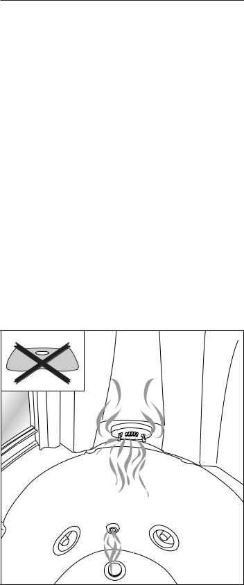
ATTENZIONE! quando si usa il bagno turco, non Anche l’utilizzo frequente del bagno turco favorisce la formazione posizionare il sedile (vedi figura sotto) sopra la boc- di calcare all’interno della caldaia.
chetta vapore della vasca (situata nel lato piedi). |
|
Non usare acqua ad una temperatura superiore ai 60 °C: i |
Dopo aver utilizzato le funzioni elettroniche del box doccia e/o la |
circuiti idraulici potrebbero danneggiarsi e inoltre aumen- |
vasca idromassaggio, spegnere sempre l’interruttore generale |
terebbe la probabilità di formazioni calcaree. |
(vedere ca. “Sicurezza elettrica”). |
10 |
Per tutti gli interventi di manutenzione e/o riparazione che comportino la sostituzione di componenti, devono essere utilizzati ricambi originali Jacuzzi®, pena la decadenza della responsabilità del Costruttore per danni derivanti dall’intervento eseguito.
PLEASE READ THESE INSTRUCTIONS CAREFULLY BEFORE INSTALLATION
the electric network and to the earth system. The cable may be routed in several ways, provided there are no loose junctions: see the “Electric safety” chapter.
Info
“Flexa Twin” shower enclosures are available in the following models: ELT10 - ELT11 and ST2l. For further information regarding the functions for each separate model, please see the price list and main catalogue.
Flexa Twin is formed of elements that are dispatched in three packages:
•hydromassage tub and transparent roof
(the roof is optional in version ST2)
•fitted-out wall and wall with mirror
•glass panes (a fixed one and a sliding one), with guides and profiles
Installation of tub
Remove the roof from the package containing the tub, and set it aside temporarily.
Place the tub in the position provided, and make sure that it is perfectly horizontal and at a height of 57 cm from the floor, by operating all the feet (central ones and external ones: 3, details 1 and 2).
Mark the position of one hole for each foot on the floor, shift the tub, bore the floor, and insert the screw anchors provided ( 3, detail 2).
IMPORTANT: check that the goods are intact on Check the perpendicularity of the walls, in order to ensure a cor- arrival, so that any claim made to the forwarding rect assembly of the parts. The compensators fitted at the ends of
agent will be prompt.
It can only be installed in a corner, with a finished (tiled) wall having no skirting board.
For maintenance operations, it will be necessary to remove the front panel of the tub and/or shower enclosure inspection panel: so a free space of at least 50 cm must be left in order to facilitate work ( 1a).
It is important to make sure that the preparations that have been made comply with the indications given in the pre-installation sheet.
Preparation of water and power connections
For a correct operation of the apparatus, it is necessary to ensure the required flow rate and pressure of the hot and cold water (see the table with the technical specifications and dimensions).
You must provide a single pair of wall outlets for hot and cold water (copper pipe, Ø 14 mm): they must protrude and end with a downward 90° elbow (1/2” M) ( 2). These outlets will be connected to the flexible pipes coming from the mixer tap assembly (in a model with single-control mixer tap) or from the filter (in a model with thermostatic mixer tap).
The drain on the floor (or on the wall, flush with the floor) must be placed at the correct distance from the drain hole of the tub, depending on the siphon to be fitted (not supplied) ( 2).
If you wish to connect an ELT model to an alarm circuit, you will need to provide the necessary connection.
Models equipped with a telephone require the preparation of a chase in the wall or an external channel for the passage of the supplied telephone cable. This cable is already connected inside the “telephone box” (see electric diagram) and a length of approx. 10 metres should be left for connection to the telephone socket to be provided by the Customer.
Provision must be made also for the connection of the electric box (which is fastened to the framework of the tub: see 2) to
the glass panes can compensate for up to 5 mm. If there is a considerable perpendicularity error in the walls, you can correct it by means of spacers made of wood or other materials, moving the tub away from the wall, if necessary ( 4).
Before you begin the assembly operations, make sure that the tub is in working order, and check it for leakage, particularly in points that cannot be reached by only removing the front panel.
Installation of fitted-out wall
Move the tub away from the corner as much as you need to be able to work easily.
Apply a small amount of silicone around the holes, as shown in 5.
Open the package that contains the walls, set the wall with mirror aside, and take the fitted-out wall.
The package contains a little bag with all the screws you will need for assembly.
Position the fitted-out wall so as to cause the holes on its framework to coincide with the holes on the tub ( 6, details 1 and 2).
From under the tub edge, mount the screws and washers, without tightening them completely ( 6, details 1 and 2).
Connect the waterfall pipe to the pipe fitting on the tub ( 7).
Connect the flexible pipe coming from the mixer tap assembly to the pipe fitting of the filling tap ( 8).
Using a metal band, connect the silicone pipe of the boiler outlet to the fitting that is already connected to the tub drain 9, detail 1.
Connect pipe (A) of the steam outlet in the tub ( 9, detail 3) to the other pipe fitting on the tub rim (detail 2).
11

The other steam outlet (on the fitted-out wall) has already been connected by the manufacturer.
IMPORTANT! Be careful not to exchange the two pipes.
ELECTRIC CONNECTION OF SHOWER ENCLOSURE
(MOD. ELT10/11)
Remove the insulating protective devices from the electric cable on the corner of the tub (coming from the electric box of the tub), and connect the cable to the junction box ( 10, details 1 and 2), respecting its polarity (brown: phase; blue: neutral; green and yellow: earth).
•Connect the two cables coming from the electric wiring box, positioned in the left corner, for the tub ( 10, detail 1).
•Take off the wiring junction box cover, remove the insulating protection from the wires of cable B and connect this to the terminal board (detail 2), according to polarity (brown: phase, blue: neutral, yellow/green: earth).
•Repeat the same operations for the cable (A) with only two wires, connecting it to the right terminal board.
Overturn the structure and position the upper guide on the fixed glass pane. Repeat these operations for the lower guide (stages 5, 6, 7, 8).
Apply silicone to the heads of the guides that are still free (stage 9), and fasten the upright to the guides by means of 4 (2+2) screws (stage 10).
Installation of fixed glass panel
Apply silicone around the holes on the tub rim ( 13, details 1, 4, 5 and 5a).
Position the assembled glass pane on the tub rim and fasten it to the uprights of the fitted-out wall and to the wall with mirror, by means of (5+5) screws ( 13, details 2 and 3).
From under the tub rim, fasten the glass pane by means of: 4 screws for the lower guide ( 13, detail 4).
2 (1+1) screws for the uprights ( 13, details 5 and 5a).
Carefully tighten the cable clamp, and close Fasten the fitted-out wall to the tub for good by completely tight- the junction box, taking care to position its lid ening the screws of the framework ( 6, details 1 and 2). correctly.
UNIPOTENTIAL CONNECTION
(MOD.ST2)
In ST2 models, pass the green-and-yellow cable with Faston connector (coming from the terminal screwed to the framework of the fitted-out wall and marked with symbol  ), through the cable clamp on the tub rim ( 10, detail 3) and connect it to the terminal near the pump, marked with symbol
  .
.
Carefully tighten the cable clamp, in order to avoid dripping under the tub.
Apply a small quantity of silicone to the entire mating profile of the fitted-out wall with the wall with mirror ( 14, detail 1).
Carefully apply silicone to the mating profile of the walls with the tub edge ( 14, details 2 and 4) and of the walls with the uprights of the glass panes (detail 3).
These applications of silicone ensure that the system is waterproof during normal use, and even in particular conditions, for instance when the shower is directed to the points of junction between the various elements.
Installation of wall with mirror
Apply a small quantity of silicone around the holes indicated in
11, detail 1.
Position the wall with mirror, place it against the fitted-out wall, and fasten it to the latter by means of 6 screws, 6 nuts and 12 (6+6) washers ( 11, detail 2).
Installation of roof (if any)
This operation must be performed by at least two persons. Place the roof upon the fitted-out wall, the wall with mirror and the glass pane guide ( 15): the edge of the roof must fit in the race of the upper guide (detail 1).
Pass the rubber pipe (the only pipe that is not connected and comes from the solenoid valve assembly) through the hole on he roof (detail 2). Fasten it to the pipe fitting of the revolving shower (detail 3).
Assembly of fixed glass panel
Remove from the wooden crate the fixed glass pane, the sliding door, the upright, the upper guide, the lower guide, and the two compensators for fastening the structure to the wall.
The lower guide is the one with the gasket.
(See 12): Apply silicone to the lower guide for all the length of the glass pane (stage 1) and on its head (stage 2).
Position the guide on the upside-down glass pane. Keeping the guide against the upright of the glass pane, fasten it with 1 screw (stage 3) Then fasten the guide to the upright with 2 screws (stage 4).
Connection of telephone (if any)
Version ELT10 is equipped with a speakerphone whose controls are built into the electronic display.
To activate it, connect it to a suitably provided telephone socket, using the cable that is bundled and fastened to the back of the shower enclosure (it is approximately 10 metres long). For this connection, you must provide a track in the wall or an external raceway in which the cable will be routed up to the telephonic socket.
It is the customer’s responsibility to choose the position of the telephone socket, depending on the length of the cable supplied.
12

It is the installer’s responsibility to make the connection of this cable (and/or to fit the telephonic plug) and to ensure that current regulations relevant to electric and telephonic systems are complied with.
Connection of alarm (if any)
In versions ELT10 and ELT11, the design provides for an “alarm”, whose presence is marked by the key (  ). on the display. If the building has a “call for help” circuit, it can be connected to the shower enclosure and controlled by that key.
Within the electronic box, near the “ALARM” waterproof cable clamp, there are two terminals identified by the letters “ALL”, which correspond to the normally-open contacts of a relay. To the latter, the installer can connect the “calling for help” circuit, which must comply with the current provisions of the law and specific regulations in force in that country.
When the alarm key is pressed on the display, a relay, which is already fitted inside the electronic box, activates the “calling for help” device for about 15 seconds. The “calling for help” device (bell, buzzer, lamp, etc.) can be supplied either with a 220-240-V or a low voltage power supply; in any case, you must make sure that its power absorption does not exceed 10 A.
The connection of the alarm circuit must be made by means of a cable whose characteristics are not less that those of type H 05 VV-F 2x2.5 mm2. The use of this cable is indispensable to ensure that the cable clamp fitted on the box has the degree of waterproofness required by the regulations.
To ensure protection against splashes, the cable clamp of the alarm output is protected by a lid that must be removed ONLY when the “alarm” connection is made.
Completion and checks
Move the shower enclosure near the corner where it is to be installed, in order to connect the flexible pipes coming from the mixer tap assembly ( 16, detai 1), or, if there is a thermostatic mixer tap, from the filters (detai 2), to the hotand cold-water connections on the wall.
In any case, the shower enclosure must be kept away from the walls, in order to verify its waterproofness during the cycle in which the various functions are tested.
Place the sliding door transversally into the shower enclosure ( 17); during this operation, protect the bottom of the tub adequately.
Fit the sliding door, first inserting the upper wheels, then ensuring that the lower wheels come into the respective guide ( 17).
Make sure that the glass panel is perpendicular and slides smoothly. If an adjustment is required, loosen the screw that fastens the knob, turn the knob as much as needed, then tighten the screw again firmly (details 3 and 4).
Screw the shower head into the flexible pipe and the latter into the connection on the fitted-out wall ( 18). Then fit the shower head on its support.
Provisionally connect the tub drain to the wall drain by means of a pipe, and check whether there is any leakage.
Connect the electric box of the tub to the power supply network (see chapter “Electrical safety”), respecting the indications of the colours (phase, neutral, ground). Tighten the cable clamp carefully. It is advisable also to check the operation of the differential switch, by pressing the key marked “T” (test).
Check all connections (hydraulic and electrical) and run a cycle to test all functions of both the bath and equipped panel.
The diverter ( 1, detail 2) makes it possible to direct the water flow either to the “Power Fall” or to the hydromassage in the tub.
Installation of compensators
After you have made sure that there is no leakage and that the system in is working order, remove the provisional connection to the drain, and, if necessary, disassemble the sliding door, in order to facilitate the subsequent shifting of the shower enclosure.
Move the shower enclosure near the walls and insert the compensator on the fixed glass pane.
Using the holes on the compensator as a guide, bore the glass pane upright and fasten the compensator by means of 3 screws with caps ( 19, phases 1, 2 and 3).
Screw the catches (supplied in the bag containing the screws) onto the upright of the fitted-out wall ( 20, detail 1).
Position the other compensator on the corner of the tub, respecting the dimension indicated in Figure 20, detail 2. Adjust its perpendicularity, and mark the positions of the holes (details 3 and 4).
Remove the compensator, and make the holes in the points you have marked. Re-position the compensator and fasten it to the wall by means of 3 screws and screw anchors ( 21).
Installation of inspection panel
Fit the clothes hook on the inspection panel, by means of 2 screws ( 22, detail 1).
Fit the inspection panel, first inserting it into the compensator, then hitching it to the catches ( 22, detail 2-4).
Using the holes on the compensator as a reference, bore the inspection panel, then apply 3 screws and their caps ( 23).
13

Fastening the system to walls and floors
Mount the square plate ( 24, detail 1) on the framework of the fitted-out wall. Mark the hole on the wall, bore, and fasten the square plate:
•to the wall, by means of 1 screw and screw anchor;
•to the framework, by means of 2 nuts ( 24, detail 3).
Mount the other square plate ( 25) on the opposite corner, mark the hole, bore, and fasten the square plate:
•to the wall, by means of 1 screw and screw anchor (detail 2);
•to the upright of the wall with mirror, by means of 1 screw (detail 3).
Re-assemble the sliding door (if you had disassembled it), following the indications given in Chapter “Completion and checks”. Connect the drain to the floor drain for good.
Anchor the tub for good, by means of the screws supplied, using the screw anchors you had previously inserted in the floor ( 1, detail 3).
Installation of front panel on tub
Fasten the 2 metal supports (A) to screw anchors (B) under the tub rim ( 1, detail 4).
Insert springs (C) ( 1, detail 5) onto the props on the tub corners, make them slide up as far as they will go, and push them sideways so as to cause them to be positioned inside the tub rim.
Insert ring (D) in the race of the prop.
Position square plates (E), respecting the indicated dimensions ( 1, detail 6), then lock them in position by means of nuts (F).
Move the panel towards the tub, and, pressing on the upper edge of the panel, insert it between the central-lateral springs and the tub rim ( 1, detail 7).
Move the panel up, and align the holes in it with the slots on the brackets.
Fasten the panel with 4 screws ( caps supplied.
Electrical safety
Jacuzzi® hydromassage products are safe appliances, manufactured in compliance with EN 60335.2.60, EN 61000, EN 55014 and TS 2000/01 norms and are approved by the TÜV Certifying Institute. Installation must be carried out by qualified and authorized personnel and must guarantee full compliance with the national regulations in force.
It is the installer’s responsibility to select the materials in relation to their use, to carry out the work cor-
rectly, and to check the condition of the network to which the apparatus will be connected and its capability to ensure user safety.
The Flexa Twin shower enclosures are class “I” apparatus, and must be anchored securely and connected permanently, without any intermediate joints, to the electric network and ground system.
The electric network and ground system of the building must be in working order and must comply with
the provisions of the law and specific regulations in force in that country.
For the connection to the electric network, it is necessary to install a disconnecting multiple-pole switch, placing it in an area that complies with safety prescriptions for bathrooms. The multiple-pole switch must ensure a contact opening of at least 3 mm, and must be suitable for a voltage of 220-240 V and a current up to 16 A.
The switch and electric devices, in compliance with regulations, must be placed in an area that cannot be
reached by the person who is using the shower enclosure.
The installation of electric devices and apparatus (sockets, switches, etc.) in bathrooms must comply with the provisions of the law and regulations in force in that country. In particular, the installation of any electric device is forbidden in the area surrounding the shower enclosure for a distance of 60 cm and a height of 225 cm ( 30).
For the connection to the electric network of the building, a cable with sheath having characteristics not inferior to type H 05 VV-F 3x2,5 mm2 must be used.
The electric network of the building must be equipped with a 0.03-A differential switch.
The FLEXA TWIN shower enclosures are equipped with a terminal, fitted on the framework and marked with the symbol  , for the equipotential connection of the surrounding metal masses, as laid down by the EN 60335.2.60 standards.
JACUZZI EUROPE declines all responsibility in the following cases:
if the installation is performed by personnel not qualified and/or not certified to perform the said installation.
if the provisions of the law and regulations relevant to the electric networks of buildings, in force in the country in which the installation is performed, are not complied with;
if the instructions for installation and maintenance contained in this manual are not followed;
if unsuitable and/or uncertified materials are used for the installation;
if the installation of the Flexa Twin shower enclosures does not comply with the regulations mentioned above;
if the installer performs incorrect operations that reduce the degree of protection against water jets, change the protection against electrocution by direct or indirect contact, or generate conditions of abnormal insulation, current dispersion or overheating;
if some components or portions of the equipment are replaced or modified with respect to the state in which they have been supplied, causing the manufacturer’s liability to become null and void;
14
if the equipment is repaired by unauthorised personnel, or using spare parts other than the original ones produced by Jacuzzi Europe.
Warnings and notes
The Flexa Twin is not a toy. NEVER LEAVE UNSUPERVISED CHILDREN IN THE SHOWER ENCLOSURE, PARTICULARLY DURING THE OPERATION OF THE TURKISH BATH.
Jacuzzi® shower enclosures can be used for household purposes and other similar uses, and must not be installed out of doors. Make sure that the installation is carried out by qualified technicians, in compliance with the laws and regulations in force in the country where the shower enclosure is installed.
It is dangerous for a person inside the shower enclosure to use devices connected to the electrical network: no electrical devices must be accessible from the shower enclosure.
In the Turkish bath, the peak temperature, at the height of the user’s bust, is approximately 45°C, allowing for a room temperature of approximately 20°C.
After having used any “water jet” function, turn off the mixer tap and/or stopcock. It is advisable, moreover, to set the diverter knob to position “water into tub”.
If the Flexa Twin is supplied with hot water from an economic-type gas boiler with mechanical flame modulation, the boiler may not be able to supply water continuously at the required temperature, so there may be some variations in the water temperature.
In this case, if it is not possible to replace the boiler with an electronicmodulation one, it is advisable to have a qualified technician lock the flame modulation of the boiler, in order to use only the mixer tap of the shower enclosure to regulate the water temperature.
The Jacuzzi® thermostatic mixer is suitable for hot water supplied from pressurized accumulators. If an instant hot water heater is used, make sure that it has a power of not less than 18 kW (250 kCal/mn). If a gas model is used, a model with variable power should be used according to the volume of water to be drawn off.
Do not use hot water accumulators without pressure.
The water mains (hot/cold water) must ensure pressures that are as balanced as possible: a considerable difference in pressure may prevent a correct and speedy adjustment of the water temperature.
If the water is very hard, it is advisable to install a decalcifying device, in order to prevent or reduce the formation of scale and to
IMPORTANT! The steam comes out at a temperature cut down the need for the scale removal cycle (see the “Use and near 100°C. During the Turkish bath, do not keep your maintenance” manual):
legs, or other parts of your body, in the trajectory of The frequent use of the Turkish bath increases the formation of the steam jet; or keep them at least 40 cm away from scale inside the boiler.
the steam outlets.
Always switch off the master switch after using the shower enclo-
IMPORTANT! When you use the Turkish bath, do not sure and/or hydromassage tub electronic functions (see “Electri- position the seat above the steam outlet on the tub, cal Safety” chapter).
on the side of your feet (see the figure below).
For all maintenance and/or repair operations that require the replacement of components, you must use original Jacuzzi®, spare parts. Failure to comply with this prescription causes the liability of the manufacturer for damages due to the operation performed to become null and void.
Do not use water at a temperature higher than 60°C: this might damage the water circuits and might increase the formation of scale.
15

LIRE INTÉGRALEMENT LES INSTRUCTIONS AVANT DE PROCÉDER À L'INSTALLATION
Infos
Les cabines de douche “Flexa Twin” sont disponibles dans les versions ELT10, ELT11 et ST2; pour plus de détails quant aux fonctions dont dispose chacun des modèles, se reporter aux tarifs et au catalogue général.
Flexa Twin se compose d’éléments emballés dans trois colis :
•la baignoire d’hydromassage + le toit transparent (le toit est en option dans la version ST2);
•la paroi aménagée + la paroi avec miroir ;
•les vitres (une fixe et une coulissante) + les glissières et les profils.
Il faut également effectuer le branchement du boîtier électrique (fixé au bâti de la baignoire, 2) au secteur et à la mise à la terre. Le câble peut suivre différents parcours à condition qu’il n’y ait pas de prises volantes ; se reporter au chap. “Sécurité électrique”.
Installation de la baignoire
Retirer le toit de l’emballage de la baignoire et le mettre de côté.
Positionner la baignoire dans l’angle choisi et vérifier la mise à niveau et la hauteur du sol qui doit être de 57 cm, en agissant sur chaque pied (pieds centraux et externes, 3, pos.1 et 2).
Marquer sur le sol la position du trou pour chaque pied avant, déplacer la baignoire, percer le sol et introduire les chevilles fournies ( 3, pos.2).
IMPORTANT: à la livraison, s'assurer du bon état de Vérifier également la perpendicularité des murs afin que le mon- la marchandise et en cas de dommages, adresser tage des différentes parties soit correctement effectué ; les com- sans attendre une réclamation au transporteur. pensateurs (montés aux extrémités des vitres) permettent de
L’installation est prévue uniquement en angle, sur des murs finis (déjà revêtus) et sans plinthe.
Pour les éventuelles opérations de maintenance, il faut enlever le panneau de façade de la baignoire et/ou le panneau d’inspection de la cabine de douche : laisser un espace libre d’au moins 50 cm pour que l’opérateur puisse travailler facilement ( 1a).
Il est recommandé de vérifier que les dispositifs de pré-installation sont conformes aux indications reportées dans la fiche technique.
récupérer jusqu’à 5 mm. Les éventuelles erreurs importantes de perpendicularité des murs peuvent être récupérées à l’aide d’entretoises en bois ou dans un autre matériau, en éloignant au besoin la baignoire du mur ( 4).
Avant de commencer les opérations de montage, contrôler que la baignoire est en parfait état et qu’il n’a aucune fuite dans des points qui ne sont pas accessibles en retirant simplement le panneau de façade.
Raccordements hydrauliques et électriques
Pour le fonctionnement correct de l’installation, il faut garantir les débits et les pressions adéquates de l’eau chaude et froide (voir le tableau des “Caractéristiques techniques et dimensions”).
Prévoir un seul couple de sorties sur le mur pour l’eau chaude et froide (tuyau en cuivre de Ø 14 mm), qui doivent dépasser et se terminer par un coude à 90° (1/2” M) tourné vers le bas ( 2). Il faudra raccorder à ces sorties les flexibles provenant du groupe mitigeur (modèle avec mitigeur monocommande) ou des filtres (modèle avec mitigeur thermostatique).
L’orifice d’évacuation sur le sol (ou sur le mur, au ras du sol) devra se trouver à une distance adéquate de la bonde de la baignoire, en fonction du siphon (non fourni) que l’on souhaite utiliser ( 2).
Pour raccorder un modèle ELT à un circuit d'alarme, prévoir le branchement nécessaire à cet effet.
Pour les modèles dotés de téléphone, il est nécessaire de réaliser une saignée dans le mur ou d'installer une gaine externe pour le passage du fil téléphonique fourni à cet effet. Ce fil est déjà branché à l'intérieur du "boîtier téléphone" (voir schéma électrique) et sa longueur est de 10 mètres pour permettre le branchement à la prise téléphonique mise en place par le client.
Installation de la paroi aménagée
Éloigner la baignoire de l’angle d’installation de manière à pouvoir travailler facilement.
Mettre un peu de silicone autour des trous, comme cela est sur la 5.
Ouvrir l’emballage, mettre de côté la paroi avec le miroir et retirer la paroi aménagée.
L’emballage contient un sachet avec la visserie nécessaire pour les phases de montage.
Positionner la paroi aménagée de sorte que les trous du bâti coïncident avec ceux qui sont présents sur la baignoire ( 6, pos.1 et 2).
Sous le bord de la baignoire, monter les vis et les rondelles, sans les serrer complètement ( 6, pos.1 et 2).
Raccorder le tuyau de la cascade au raccord présent sur la baignoire ( 7).
Raccorder le flexible provenant du groupe mitigeur au raccord du bec ( 8).
Avec un collier métallique, raccorder le tuyau en silicone de l’évacuation de la chaudière au raccord (déjà raccordé à la
16

bonde d’évacuation de la baignoire) indiqué sur la 9, pos.1.
Raccorder le tuyau (A) de sortie de la vapeur dans la baignoire ( 9, pos.3) à l’autre raccord présent sur le bord de la baignoire (pos.2). L’autre orifice de sortie de la vapeur (montée sur la paroi aménagée) a déjà été raccordé en usine.
( 12) : siliconer la glissière inférieure sur toute la longueur de la vitre (phase 1) et à l’extrémité de tête (phase 2).
La positionner sur la vitre (retournée). Tenir la glissière contre le montant de la vitre, la fixer avec 1 vis (phase 3) et au montant avec 2 vis (phase 4).
ATTENTION! Ne pas intervertir les deux tuyaux.
Retourner la structure et positionner la glissière supérieure sur la vitre fixe. Répéter les opérations décrites pour la glissière inférieure (phase 5, 6, 7, 8).
BRANCHEMENT ÉLECTRIQUE DE LA CABINE DE |
|
DOUCHE (MOD.ELT10/11) |
Mettre de la silicone sur les extrémités de tête des glissières |
Enlever les protections isolantes du câble électrique positionrestantes (phase 9) puis fixer le montant aux glissières avec 4
né sur l’angle de la baignoire (provenant du boîtier électrique |
(2+2) vis (phase 10). |
|
de la baignoire) et le brancher à la boîte de dérivation ( |
|
|
10, pos.1 et 2), en respectant la polarité (marron : phase ; |
Installation de la vitre fixe |
|
bleu : neutre ; jaune/vert : terre). |
||
• Procéder au branchement des deux câbles provenant du |
|
|
Mettre du silicone autour des trous du bord de la baignoire ( |
||
boîtier électrique de la baignoire et positionnés à hauteur de |
||
l'angle gauche ( 10, détail 1). |
13, pos.1, 4, 5 et 5a). |
|
• Retirer le couvercle du boîtier de dérivation, retirer les protec- |
|
|
tions isolantes des conducteurs du câble (B) et brancher ce |
Positionner la vitre assemblée sur le bord de la baignoire et la |
dernier au bornier (détail 2) en veillant à respecter les polarifixer aux montants de la paroi aménagée et de la paroi avec
tés (marron: phase, bleu: neutre, jaune/vert: terre). |
miroir avec 10 (5+5) vis ( 13, pos.2 et 3). |
|
• Effectuer les mêmes opérations pour le câble (A) pourvu de |
|
|
deux conducteurs uniquement, brancher ce câble au bornier |
Par le dessous du bord de la baignoire, fixer la vitre avec : |
|
de droite. |
4 |
vis pour la glissière inférieure ( 13, pos.4). |
|
2 |
(1+1) vis pour les montants ( 13, pos.5 et 5a). |
S’assurer que le passe-câble est bien serré et
la boîte de dérivation a été refermée, en Fixer définitivement la paroi aménagée à la baignoire en serrant
veillant à ce que le couvercle soit correcte- complètement les vis du bâti ( 6, pos.1 et 2). ment positionné.
Mettre un peu de silicone sur tout le profil d’assemblage de la BRANCHEMENT ÉQUIPOTENTIEL paroi aménagée avec la paroi avec miroir ( 14, pos.1).
(MOD.ST2)
Sur les modèles ST2, faire passer le câble jaune-vert à faston (provenant de la borne vissée sur le bâti de la paroi aménagée et portant le symbole  ), à travers le pressecâble sur le bord de la baignoire ( 10, pos.3) et le brancher à la borne présente à proximité de la pompe et qui porte également le symbole
  .
.
Bien serrer le presse-câble afin d’éviter les éventuels suintements sous la baignoire.
Siliconer soigneusement l’assemblage entre les parois et le bord de la baignoire ( 14, pos.2 et 4) et entre les parois et les montants des vitres (pos.3).
L’application de silicone garantit l’étanchéité hydraulique durant l’utilisation normale mais aussi dans des conditions particulières, par exemple quand la douche est orientée directement sur les points de raccordement des divers éléments.
Installation de la paroi avec miroir
Mettre un peu de silicone autour des trous indiqués sur la
11, pos.1.
Positionner la paroi avec miroir en la plaçant contre la paroi aménagée et la fixer à celle-ci avec 6 vis, 6 écrous et 12 (6+6) rondelles ( 11, pos.2).
Installation (éventuelle) du toit
Pour cette opération il faut être au moins deux : positionner le toit sur la paroi aménagée, la paroi avec miroir et la glissière des vitres ( 15) : le bord du toit doit rester à l’intérieur de la gorge de la glissière supérieure (pos.1).
Faire passer le tuyau en toile caoutchoutée (c’est le tuyau non raccordé, qui provient du groupe des électrovannes) à travers le trou présent sur le toit (pos.2) et le fixer au raccord de la douche rotative, en vissant la bague filetée (pos.3).
Assemblage de la vitre fixe
Retirer de la cage en bois la vitre fixe, la porte coulissante, le montant, les glissières supérieure et inférieure et les deux compensateurs pour la fixation au mur.
Branchement (éventuel) du téléphone
La version ELT10 est équipée d’un téléphone «mains libres» dont les commandes sont incorporées au panneau électronique. Pour l’activer il faut le brancher à une prise téléphonique pré-
La glissière inférieure est la glissière avec la installée en utilisant le câble enroulé et tenu par un collier à garniture. l’arrière de la cabine de douche (~10 m).
17

Pour effectuer le branchement, il faut prévoir une trace sous le mur (ou une conduite externe), dans laquelle on fera passer le câble jusqu’à la prise téléphonique.
Le client devra choisir la position de la prise téléphonique en fonction de la longueur du câble fourni. L’installateur devra aussi effectuer le branchement de ce câble (et/ou monter la fiche téléphonique) et garantir le respect des normes en vigueur en matière d’installation électrique et de téléphone.
Vérifier la perpendicularité et le coulissement de la vitre ; si un éventuel réglage est nécessaire, desserrer la vis qui bloque la molette, la tourner et bien revisser la vis (pos.3 et 4).
Visser le flexible à la douchette et au raccord présent sur la paroi aménagée ( 18) puis monter la douchette sur son support.
Raccorder provisoirement la bonde de la baignoire à l’évacuation au sol avec un tuyau, en faisant attention aux éventuelles fuites d’eau.
Branchement (éventuel) de l’alarme
|
|
Raccorder le boîtier électrique de la baignoire au secteur (voir |
|
Les versions ELT10 et ELT11 ont été projetées avec un |
chap. “Sécurité Électrique”), en respectant les symboles |
||
dispositif d’alarme indiqué sur le panneau électronique |
(phase-neutre-terre) et sans oublier de serrer soigneusement le |
||
par la touche ( ). Si l’habitation dispose d’un circuit d’ap- |
presse-câble ; il est conseillé de contrôler le fonctionnement du |
||
pel/secours, ce circuit peut être raccordé à la cabine de |
disjoncteur différentiel en appuyant sur la touche “T” (test). |
||
douche et commandé avec cette touche. |
|
|
|
|
|
Vérifier tous les raccordements (hydrauliques et électriques) et |
|
À l’intérieur du boîtier électronique, à proximité du passe- |
effectuer un cycle d’essai de toutes les fonctions de la baignoi- |
||
câble étanche “ALARME”, il y a deux bornes identifiées par le |
re et de la paroi aménagée. |
||
mot “ALL”, qui correspondent aux contacts normalement |
|
Le déviateur ( 1, pos.2) permet de diriger le flux |
|
ouverts d’un relais, auxquels l’installateur peut brancher le cir- |
|||
cuit d’appel/secours qui doit être conforme aux dispositions |
d’eau vers la cascade “Power Fall” ou vers l’hy- |
||
de la loi et aux normes nationales spécifiques. |
|
dromassage dans la baignoire. |
|
Quand on appuie sur la touche «alarme», sur le panneau élec- |
Installation des compensateurs |
||
tronique, un relais, déjà monté à l’intérieur du boîtier électro- |
|||
nique, active le dispositif d’appel/secours pendant 15 |
|
|
|
|
|
||
secondes environ. L’indicateur d’appel (sonneries, vibreurs, |
Après s’être assurés qu’il n’y a pas de fuites et que l’installation |
||
voyants lumineux, etc.) peut être alimenté aussi à 220-240V |
fonctionne parfaitement, enlever le branchement provisoire de |
||
qu’à basse tension, mais il faut s’assurer que l’absorption est |
l’évacuation et démonter éventuellement la porte coulissante |
||
inférieure à 10 A. |
pour faciliter ensuite les déplacements de la cabine de douche. |
||
Le branchement du circuit d’alarme devra être effectué au |
Approcher la cabine de douche des murs et positionner le com- |
||
moyen d’un câble ayant les caractéristiques minimums du type |
pensateur sur le montant de la vitre fixe. |
||
H 05 VV-F 2x2,5 mm2. L’utilisation de ce câble est indispensable |
|
|
|
pour s’assurer que le presse-câble monté sur le boîtier garantit |
En utilisant comme guide les trous présents sur le compensa- |
||
le degré de protection (étanchéité) prévu par les normes. |
teur, percer le montant de la vitre et fixer le tout avec 3 vis à |
||
|
|
capuchons ( 19, phases 1, 2 et 3). |
|
Pour garantir la protection contre les jets d’eau, le
presse-câble de sortie de l’alarme est fermé en Visser les cliquets (présents dans le sachet de la visserie) sur le
usine avec un bouchon qui ne doit être enlevé que le branchement “alarme” est effectué.
montant de la paroi aménagée ( 20, pos.1).
Positionner l’autre compensateur sur l’angle de la baignoire selon la mesure indiquée sur la 20, pos.2 ; régler la perpendicularité et marquer la position des trous (pos.3 et 4).
Opérations complémentaires et vérifications
Approcher la cabine de douche de l’angle d’installation de manière à raccorder les flexibles provenant du groupe mitigeur ( 16, pos1) ou, en cas de mitigeur thermostatique, des filtres (pos.2), aux raccords muraux de l’eau chaude et froide.
Enlever le compensateur, percer au niveau des marques et repositionner le compensateur, en le fixant au mur avec 3 vis + chevilles ( 21).
Installation du panneau d’inspection
La cabine de douche doit dans tous les cas être
éloignée des murs de manière à vérifier que Monter le porte-vêtements sur le panneau d’inspection avec 2
l’étanchéité hydraulique, durant le cycle d’essai des différentes fonctions, est parfaite.
Faire entrer transversalement la porte coulissante à l’intérieur de la cabine de douche ( 17) ; il est recommandé de mettre une protection adéquate sur le fond de la baignoire.
Monter la porte coulissante, en enfilant d’abord les galets du haut ; ensuite, vérifier que les galets inférieurs sont positionnés dans leur glissière ( 17).
vis ( 22, pos.1).
Monter le panneau d’inspection, en l’enfilant d’abord dans le compensateur puis en l’accrochant aux cliquets ( 22, pos.2-4).
Prendre comme référence les trous présents sur le compensateur, percer le panneau d’inspection puis appliquer 3 vis à capuchons ( 23).
18
 Loading...