


JPX-300 UNDERCOUNTER DISHMACHINE SERIES
TECHNICAL MANUAL
INSTALLATION MANUAL FOR EXPORT UNITS
SERVICE MANUAL FOR DOMESTIC UNITS
FOR JACKSON MODELS:
JPX-300H
JPX-300HC
JPX-300HN
JPX-300L
March 07, 2007
P/N 7610-002-73-30 (Revision N)
Jackson MSC LLC. P.O. BOX 1060 HWY. 25E
BARBOURVILLE, KY. 40906 PHONE (606) 523-9795 FAX (606) 523-9196 www.jacksonmsc.com

|
REVISION |
REVISION |
MADE |
APPLICABLE |
DETAILS |
|
|
DATE |
BY |
ECN |
|
||
|
|
|
|
|||
|
|
|
|
|
|
|
|
|
|
|
|
Added 6” M24 Stand Assembly. Converted to new layout. Added |
|
|
|
|
|
6961, 6977 |
note for Rinse Arm Assembly (JPX-300H units only) Added 18” |
|
|
E |
04-01-04 |
MAW |
6940, 6932 |
M24 Stand Assembly. Added alternate Top Flat Panel. Added 208- |
|
|
|
|
|
6912, 7006 |
240V/60Hz Timer. Added Splash Shield. Changed thermostat |
|
|
|
|
|
|
mounting bracket (05700-011-73-72 to 05700-011-81-64) |
|
|
|
|
|
|
|
|
|
|
|
|
6962 |
Corrected rinse plumbing plate #. Changed retaining ring and cap- |
|
|
F |
01-26-05 |
MAW |
tive stud. Added JPX-300HC model. Added drain quench system. |
|
|
|
7068 |
Added GO*BOX kit. Added Deliming Instructions. Add dimension |
|
|||
|
|
|
|
|
||
|
|
|
|
|
drawing for JPX-300L. Removed JPX-300L model designation. |
|
|
|
|
|
|
|
|
|
G |
04-13-05 |
MAW |
N/A |
Corrected the wash motor numbers. |
|
|
|
|
|
|
|
|
|
|
|
|
|
Replace 04820-300-07-00 vacuum breaker with 04820-003-06- |
|
|
|
|
|
7383, 7271 |
13. Add dimension drawing of the JPX-300HN. Replace 05945- |
|
|
H |
08-25-05 |
MAW |
121-44-89 & 05945-002-49-35 timers with 05945-003-02-90 |
|
|
|
7310, 7404 |
|
||||
|
5Min/7cam timer. Replace 05945-002-13-34 timer with 05945- |
|
||||
|
|
|
|
7332 |
|
|
|
|
|
|
003-02-18. Updated Trouble Shooting Section. Removed JPX- |
|
|
|
|
|
|
|
|
|
|
|
|
|
|
300LP model designation, added JPX-300L. |
|
|
|
|
|
|
|
|
|
|
|
|
|
Change thermostat from 05930-121-71-29 to 05930-510-03-79. |
|
|
|
|
|
7231, 7421 |
Change Diverter Valve Assembly number from 05700-002-23-21 |
|
|
|
|
|
to 6410-012-23-21 & Diverter Valve Assembly 05700-002-23-22 |
|
|
|
I |
11-15-05 |
MAW |
7513, 7514 |
to 06401-022-23-21. Add wash decal 09905-002-97-61 and rinse |
|
|
|
|
|
7429, 7552 |
decal 09905-002-97-62 to the kick plate panel. Change Magnet |
|
|
|
|
|
|
05930-002-68-53 to 05930-002-88-42. Add components, instruc- |
|
|
|
|
|
|
tions and schematics for use with universal timers. |
|
|
|
|
|
|
|
|
|
J |
01-13-06 |
MAW |
7602 |
Replaced Relay 05945-002-79-95 with Contactor 05945-002-74- |
|
|
20. Replaced Relay 05945-002-90-51 with Contactor 05945-109- |
|
||||
|
|
|
|
|
05-69. |
|
|
K |
01-27-06 |
MAW |
7602 |
Updated Electrical Assembly Drawings. |
|
|
|
|
|
|
|
|
|
|
|
|
|
Updated schematics 09905-003-12-84, 09905-003-12-88, 09905- |
|
|
L |
01-30-06 |
MAW |
7602 |
003-13-84 & 09905-003-13-86 to match relay to contactor |
|
|
|
|
|
|
change. |
|
|
|
|
|
|
|
|
|
M |
02-07-06 |
MAW |
7602, 7231 |
Updated schematic 09905-002-72-28 with relay to contactor |
|
|
change. Add thermostat replacement kit 6401-011-66-55. |
|
||||
|
|
|
|
|
|
|
|
|
|
|
|
|
|
|
|
|
|
|
Updated with new layout. Add Sanisure option. Removed test |
|
|
|
|
|
|
cock and pressure gauge from JPX-300L plumbing. Added con- |
|
|
N |
03-06-06 |
MAW |
7704, 7601 |
version kits for changing plastic switches to stainless steel. Added |
|
|
stainless steel switch assemblies. Corrected terminal block num- |
|
||||
|
7591, 7614 |
|
||||
|
|
|
|
ber from 5940-500-08-00 to 5940-500-02-19. Added Door Gasket |
|
|
|
|
|
|
|
|
|
|
|
|
|
|
Kit Installation Instructions. Added individual components for 50 |
|
|
|
|
|
|
HZ Motor Assembly. |
|
|
|
09-18-06 |
MAW |
N/A |
Updated for use with the HTS-11, scale prevention and corrosion |
|
|
|
control device. |
|
|||
|
|
|
|
|
|
|
|
|
|
|
|
Added tygoprene tubing to peripump assembly, corrected num- |
|
|
|
|
|
|
bers in the Go*Box Kit, moved universal timer box and cover to |
|
|
|
03-07-07 |
MAW |
7902, 7896 |
the kick plate. Added new numbers for wash pump drain hose. |
|
|
|
|
|
|
Updated pump assembly drawing. Added new numbers for the |
|
|
|
|
|
|
rinse manifold hoses. |
|
|
|
|
|
|
|
|
|
|
|
|
|
|
|
|
|
|
|
|
|
|
i

NOMENCLATURE FOR THE MODELS COVERED IN THIS MANUAL
JPX-300HN
JPX-300H = High temperature, hot water sanitizing, with a booster tank.
JPX-300HC = High temperature, hot water sanitizing, with a booster tank, and a cycle counter. JPX-300HN = High temperature, hot water sanitizing, with no booster tank.
JPX-300L = Low temperature with chemical feeder pumps.
Model:
Serial No.:
Installation Date:
Service Rep. Name:
Phone No.:
Jackson MSC Inc. provides technical support for all of the dishmachines detailed in this manual. We strongly recommend that you refer to this manual before making a call to our technical support staff. Please have this manual with you when you call so that our staff can refer you, if necessary, to the proper page. Technical support is available from 8:00 a.m. to 5:00 p.m. (EST), Monday through Friday. Technical support is not available on holidays. Contact technical support toll free at 1-888-800- 5672. Please remember that technical support is available for service personnel only.
ii

TABLE OF CONTENTS
SECTION |
DESCRIPTION |
PAGE |
I.SPECIFICATION INFORMATION
Specifications JPX-300H/HC/HN |
2 |
Specifications JPX-300L |
3 |
Dimensions JPX-300H/HC |
4 |
Dimensions JPX-300HN |
5 |
Dimensions JPX-300L |
6 |
II.INSTALLATION/OPERATION INSTRUCTIONS
|
Installation Instructions |
8 |
|
Electrical Installation Instructions |
9 |
|
Chemical Dispensing Equipment |
10 |
|
Programming Instructions for Chemical Feeder Pumps |
11 |
|
Detergent Control |
12 |
|
Operation Instructions |
13 |
III. |
PREVENTATIVE MAINTENANCE |
|
|
Preventative Maintenance |
16 |
IV. |
TROUBLESHOOTING |
18 |
V. |
SERVICE PROCEDURES |
|
|
Rinse Solenoid Valve Repair Parts Kit |
21 |
|
Vacuum Breaker Repair Parts Kit |
25 |
|
Replacing the Pump Motor/Booster Tank Heater |
27 |
|
Replacing the Drain Valve |
28 |
|
Door Gasket Kit Installation |
29 |
VI. |
PARTS SECTION |
|
|
Control Panel Assembly |
32 |
|
Control Panel Assembly with Univeral Timer |
33 |
|
Switch Panel Assembly |
34 |
|
Switch Panel Assembly with Stainless Steel Switches |
35 |
|
Chemical Feeder Pump Assembly |
36 |
|
Kick Panel Assemblies |
37 |
|
Incoming Plumbing Assembly (JPX-300H/HC) |
39 |
|
Incoming Plumbing Assembly (JPX-300HN) |
40 |
|
Incoming Plumbing Assembly (JPX-300L) |
41 |
|
Solenoid Valve Repair Kit/Vacuum Breaker Repair Kit/Water Pressure Regulator Kit (WPRK Option) |
42 |
|
Drain Valve Assembly |
43 |
|
Drain Plumbing Assembly |
44 |
|
Wash Motor to Wash Tub Assembly |
45 |
|
Pump & Motor Assembly |
46 |
|
Rinse Tank & Components/Wash Heater Kit |
47 |
|
New Style Door Assembly |
48 |
|
Old Style Door Assembly |
49 |
|
Rinse Arm & Wash Arm Assemblies |
50 |
|
Frame & Panel Components/Miscellaneous Parts |
51 |
|
Stands & Components |
52 |
|
HTS-11 Scale Prevention and Corrosion Control Device |
53 |
|
STARBUCKS™ Panel Options |
54 |
|
Go*Box Kit |
55 |
JPX-300 Technical Manual 7610-002-73-30 Rev. N
Issued: 03-06-2006 Revised: 03-07-2007
iii

TABLE OF CONTENTS
SECTION |
DESCRIPTION |
PAGE |
VII. |
SCHEMATICS |
|
|
JPX-300HN 115 V, 60 HZ, single phase |
57 |
|
JPX-300HN (Stainless Steel Switches) 115 V, 60 HZ, single phase |
58 |
|
JPX-300HN (Universal Timer & SS Switches) 115 V, 60 HZ, single phase |
59 |
|
JPX-300H/JPX-300HN 208 - 240 V, 60 HZ, single phase |
60 |
|
JPX-300H/JPX-300HN (Stainless Steel Switches) 208 - 240 V, 60 HZ, single phase |
61 |
|
JPX-300H/JPX-300HN (S/S Switches & Contactor) 208 - 240 V, 60 HZ, single phase |
62 |
|
JPX-300H/JPX-300HN (Universal Timer & SS Switches) 208 - 240 V, 60 HZ, single phase |
63 |
|
JPX-300H/JPX-300HN 460 V, 60 HZ, three phase |
64 |
|
JPX-300H/JPX-300HN (Stainless Steel Switches) 460 V, 60 HZ, three phase |
65 |
|
JPX-300H/JPX-300HN (Universal Timer & SS Switches) 460 V, 60 HZ, three phase |
66 |
|
JPX-300H/JPX-300HN-Extended Wash 460 V, 60 HZ, three phase |
67 |
|
JPX-300H/JPX-300HN-Extended Wash (Stainless Steel Switches) 460 V, 60 HZ, three phase |
68 |
|
JPX-300HC 208 - 240 V, 60 HZ, single phase |
69 |
|
JPX-300HC (Stainless Steel Switches) 208 - 240 V, 60 HZ, single phase |
70 |
|
JPX-300HC (Univeral Timer & SS Switches) 208 - 240 V, 60 HZ, single phase |
71 |
|
JPX-300L 115 V, 60 HZ, single phase |
72 |
|
JPX-300L (Stainless Steel Switches) 115 V, 60 HZ, single phase |
73 |
|
JPX-300L (Universal Timer & SS Switches) 115 V, 60 HZ, single phase |
74 |
|
JPX-300L (Universal Timer & SS Switches) 208 - 240 V, 60 HZ, single phase |
75 |
|
|
|
|
|
|
|
|
|
JPX-300 Technical Manual 7610-002-73-30 Rev. N
Issued: 03-06-2006 Revised: 03-07-2007
iv

SECTION 1:
SPECIFICATION INFORMATION
1

SECTION 1: SPECIFICATION INFORMATION
SPECIFICATIONS of the JPX-300H/JPX-300HC/JPX-300HN
PERFORMANCE/CAPABILITIES
OPERATING CAPACITY (RACKS/HOUR) |
|
RACKS PER HOUR |
30 |
DISHES PER HOUR |
600 |
GLASSES PER HOUR |
600 |
OPERATING CYCLE (SECONDS) |
|
WASH TIME |
82 |
DRAIN TIME |
28 |
RINSE TIME |
10 |
TOTAL CYCLE TIME (MINUTES) |
2 |
5 MINUTE TIMER OPERATING CYCLE (SECONDS) |
|
WASH TIME |
262 |
DRAIN TIME |
28 |
RINSE TIME |
10 |
TOTAL CYCLE TIME (MINUTES) |
5 |
TANK CAPACITY (LITERS) (GALLONS) |
|
WASH TANK |
(21.5) 5.65 |
RINSE TANK |
(11.4) 3 |
TEMPERATURES |
|
WASH---(MINIMUM) |
(65.6°C) 150°F |
RINSE---(MINIMUM) |
(82.2°C) 180°F |
WATER REQUIREMENTS |
|
INLET TEMPERATURE |
|
(40°F Rise Booster Heater) |
(60°C) 140°F |
INLET TEMPERATURE |
|
(70°F Rise Booster Heater) |
(43.3°C) 110°F |
INLET TEMPERATURE (JPX-300HN) |
(82.2°C)180°F |
WATER LINE SIZE I.P.S. (MINIMUM) |
1/2” |
DRAIN LINE SIZE I.P.S. (MINIMUM) |
1 1/2” |
FLOW PRESSURE P.S.I. |
20 ±5 |
ELECTRICAL REQUIREMENTS
WASH MOTOR HP |
3/4 |
NOTE: Typical Electrical Circuit is based upon (1) 125% of the full amperage load of the machine and (2) typical fixed-trip circuit breaker sizes as listed in the NEC 2002 Edition. Local codes may require more stringent protection than what is displayed here. Always verify with your electrical service contractor that your circuit protection is adequate and meets all applicable national and local codes. These numbers are provided in this manual simply for reference and may change without notice at any given time.
JPX-300H/JPX-300HC:
|
|
|
RINSE |
|
TYPICAL |
|
|
|
HEATER |
TOTAL |
ELECTRICAL |
VOLTS |
PH |
HZ |
RATINGS |
AMPS |
CIRCUIT |
208 |
1 |
50 |
8.2KW @ 230V |
40 A |
50 AMP |
208 |
1 |
50 |
10KW @ 230V |
47 A |
60 AMP |
230 |
1 |
50 |
8.2KW @ 230V |
47 A |
60 AMP |
230 |
1 |
50 |
10KW @ 230V |
51 A |
70 AMP |
208 |
1 |
60 |
8.2KW @ 230V |
39 A |
50 AMP |
208 |
1 |
60 |
10KW @ 230V |
42 A |
60 AMP |
230 |
1 |
60 |
8.2KW @ 230V |
46 A |
60 AMP |
230 |
1 |
60 |
10KW @ 230V |
50 A |
70 AMP |
460 |
3 |
60 |
8.2KW@480V |
11 A |
15 AMP |
460 |
3 |
60 |
10KW @480V |
14 A |
20 AMP |
JPX-300HN: |
|
|
|
|
|
|
|
|
RINSE |
|
TYPICAL |
|
|
|
HEATER |
TOTAL |
ELECTRICAL |
VOLTS |
PH |
HZ |
RATINGS |
AMPS |
CIRCUIT |
208 |
1 |
50 |
N/A |
12 A |
15 AMP |
230 |
1 |
50 |
N/A |
12 A |
15 AMP |
115 |
1 |
60 |
N/A |
24 A |
30 AMP |
208 |
1 |
60 |
N/A |
11 A |
15 AMP |
230 |
1 |
60 |
N/A |
12 A |
15 AMP |
NOTE: Always refer to the machine data plate for specific electrical and water requirements. The material provided on this page is for reference only and may be subject to change without notice.
JPX-300 Technical Manual 7610-002-73-30 Rev. N
Issued: 03-06-2006 Revised: N/A
2

SECTION 1: SPECIFICATION INFORMATION
SPECIFICATIONS of the JPX-300L
PERFORMANCE/CAPABILITIES |
|
ELECTRICAL REQUIREMENTS |
|
|
|
||||
OPERATING CAPACITY (RACKS/HOUR) |
|
WASH MOTOR HP |
|
|
3/4 |
|
|||
|
RACKS PER HOUR |
24 |
NOTE: Typical Electrical Circuit is based upon (1) 125% of the |
||||||
|
DISHES PER HOUR |
600 |
|||||||
|
full amperage load of the machine and (2) typical fixed-trip cir- |
||||||||
|
|
|
|||||||
|
GLASSES PER HOUR |
600 |
cuit breaker sizes as listed in the NEC 2002 Edition. Local |
||||||
|
|
|
codes may require more stringent protection than what is dis- |
||||||
|
|
|
played here. Always verify with your electrical service con- |
||||||
OPERATING CYCLE (SECONDS) |
|
tractor that your circuit protection is adequate and meets all |
|||||||
|
applicable national and local codes. These numbers are pro- |
||||||||
|
WASH TIME |
56 |
|||||||
|
vided in this manual simply for reference and may change |
||||||||
|
DRAIN TIME |
26 |
without notice at any given time. |
|
|
|
|||
|
|
|
|
|
|
|
|
||
|
RINSE TIME |
35 |
JPX-300L: |
|
|
|
|
|
|
|
TOTAL CYCLE TIME |
120 |
|
|
|
|
|
||
|
|
|
|
|
|
|
|
||
|
|
|
|
|
|
RINSE |
|
TYPICAL |
|
TEMPERATURES |
|
VOLTS |
PH |
HZ |
HEATER |
TOTAL |
ELECTRICAL |
||
|
|
|
RATINGS |
AMPS |
CIRCUIT |
||||
|
WASH --- (MINIMUM) |
(48.9°C) 120°F |
115 |
1 |
60 |
N/A |
14 A |
20 AMP |
|
|
WASH --- (RECOMMENDED) |
(60°C) 140°F |
208 |
1 |
60 |
N/A |
7 A |
15 AMP |
|
|
230 |
1 |
60 |
N/A |
7 A |
15 AMP |
|||
|
RINSE --- (MINIMUM) |
(48.9°C) 120°F |
|
|
|
|
|
|
|
|
RINSE --- (RECOMMENDED) |
(60°C) 140°F |
NOTE: Always refer to the machine data plate for specific |
||||||
|
|
|
|||||||
|
|
|
electrical and water requirements. The material provided on |
||||||
WATER REQUIREMENTS |
|
this page is for reference only and may be subject to change |
|||||||
INLET TEMPERATURE (RECOMMENDED) |
(60°C) 140°F |
without notice. |
|
|
|
|
|
||
|
|
|
|
|
|
|
|||
INLET TEMPERATURE (MINIMUM) |
(48.9°C) 120°F |
|
|
|
|
|
|
|
|
WATER LINE SIZE I.P.S. (MINIMUM) |
1/2” |
|
|
|
|
|
|
|
|
DRAIN LINE SIZE I.P.S. (MINIMUM) |
1 3/8” |
|
|
|
|
|
|
|
|
FLOW PRESSURE P.S.I. |
20 ±5 |
|
|
|
|
|
|
|
|
MINIMUM CHLORINE REQUIRED (PPM) |
50 |
|
|
|
|
|
|
|
|
|
|
|
|
|
|
|
|
|
|
|
|
|
|
|
|
|
|
|
|
|
|
|
|
|
|
|
|
|
|
JPX-300 Technical Manual 7610-002-73-30 Rev. N
Issued: 03-06-2006 Revised: N/A
3

SECTION 1: SPECIFICATION INFORMATION
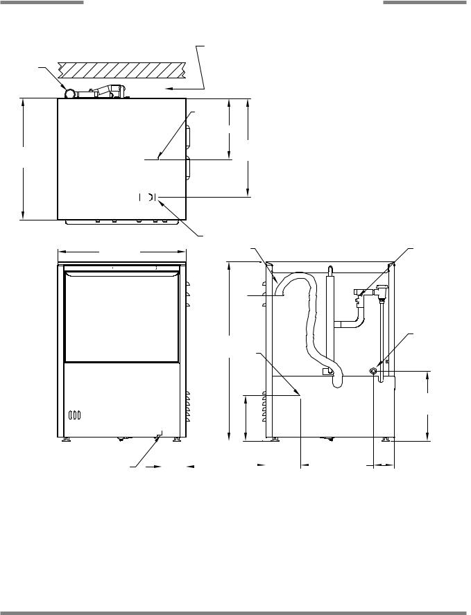
JPX-300H/HC DIMENSIONS
LEGEND
A - Water Inlet 1/2” Female Pipe Thread, 2 1/2” AFF B - Chemical Feeder Connection
C - Electrical Connection
D - Rinse Additive Connection
E - Drain Connection Flexible Hose 6’ Free Length, 1” ID x 1 3/8” OD
6 1/2”
 (16.5 cm)
4 1/2”
(11.4 cm)
|
13 1/4” |
8 1/2” |
(33.7 cm) |
(21.6 cm) |
|
|
4 5/8” (11.7 cm) |
2 1/4” |
4 1/4” |
(5.7 cm) |
(10.8 cm) |
12” (30.5 cm)
C |
19” |
(48.3 cm) 22 5/8”
(57.5 cm)
16 3/4”
(42.5 cm)
24” (60.9 cm)
33 1/4”
(84.5 cm)
|
|
DIMENSIONS |
|
|
|
Height (minimum): |
33 |
1/4” (84.5 cm) |
Inside Clearance Height: |
14 |
1/2” (36.8 cm) |
Height (maximum): |
34 |
1/4” (87 cm) |
Inside Clearance Width: |
20 |
1/4” (51.4 cm) |
Width: |
24” (60.9 cm) |
Inside Clearance Depth: |
21 |
1/4” (54 cm) |
|
Depth: |
22 |
5/8” (57.5 cm) |
Door Open Depth: |
39 |
1/2” (100.3 cm) |
Wall Clearance (minimum): |
2 1/2” (6.4 cm) |
|
|
|
|
*All dimensions are for reference only and are subject to change without notice.
JPX-300 Technical Manual 7610-002-73-30 Rev. N
Issued: 03-06-2006 Revised: N/A
4
SECTION 1: SPECIFICATION INFORMATION
JPX-300HN DIMENSIONS
2 1/2” (6.4 cm) Min. Wall Clearance
LEGEND
A - Water Inlet 1/2” ID Female Pipe Thread, 2 1/2” AFF B - Detergent Feeder Connection
C - Electrical Connection
D - Drain Connection Flexible Hose 6’ Free Length,
1” ID x 1 3/8” E E - Rinse Additive
DOOR OPEN
|
|
|
|
|
|
6 1/2” |
|
D |
|
|
|
(16.5 cm) |
|||
|
E |
|
|
||||
|
|
|
|
||||
|
|
|
|
|
|
|
|
|
|
|
|
|
|
|
|
4 1/2”
(11.4 cm)
|
|
|
|
|
|
|
|
|
|
||
12” |
|
|
|
|
|
|
|
|
|||
(30.5 cm) |
|
|
|
|
|
|
|
|
|||
|
19” |
|
|
||||||||
|
|
|
|
|
|
|
|
||||
|
|
|
|
|
(48.3 cm) |
|
|
||||
|
|
|
|
|
|
|
|
|
|
|
|
|
|
|
|
|
|
|
|
|
22 |
5/8” |
|
|
|
|
C |
|
A |
|
|
|
(57.5 cm) |
||
|
|
|
|
|
|
|
|
|
|
|
|
|
|
|
|
|
|
|
|
|
|
|
|
|
|
|
|
|
|
|
|
|
|
|
|
16 3/4”
(42.5 cm)
24”  (60.9 cm)
C |
|
B |
33 1/4” |
|
|
(84.5 cm) |
|
|
|
|
|
|
A |
13 1/4” |
|
8 1/2” |
(33.7 cm) |
|
|
|
|
||
(21.6 cm) |
|
|
|
2 1/4” |
4 5/8” (11.7 cm) |
4 1/4” |
|
2 1/4” (5.7 cm) |
|
||
(5.7 cm) |
(10.8 cm) |
|
|
|
|
||
|
DIMENSIONS |
|
|
Height (minimum): |
33 1/4” (84.5 cm) |
Inside Clearance Height: |
1/2” (36.8 cm) |
Height (maximum): |
34 1/4” (87 cm) |
Inside Clearance Width: |
1/4” (51.4 cm) |
Width: |
24” (60.9 cm) |
Inside Clearance Depth: |
1/4” (54 cm) |
Depth: |
22 5/8” (57.5 cm) |
Door Open Depth: |
1/2” (100.3 cm) |
Wall Clearance (minimum): |
2 1/2” (6.4 cm) |
|
|
*All dimensions are for reference only and are subject to change without notice.
JPX-300 Technical Manual 7610-002-73-30 Rev. N
Issued: 03-06-2006 Revised: N/A
5
SECTION 1: SPECIFICATION INFORMATION
JPX-300L DIMENSIONS
D
22 5/8”
22-5/8"
(57.5 cm)
24” (60.924"cm)
C
2-21" Minimum
Wall Clearance
B
12"
19”
19"
(48.3 cm)
LEGEND
A - Detergent Feeder Connection
B - Electrical Connection
C - Water Inlet 1/2” Female Pipe Thread, 2 1/2”
AFF
D - Rinse Additive Connection
E - Drain Connection Flexible Hose 6’ Free
Length, 1” ID x 1 3/8” OD
3 3/4” (9.5 cm)
C
E D
24” (61 cm)
A
33 1/4”
(8433.-51/4"cm) B
12 13/16”
12-13/16"
(84.5 cm)
8-1/2"
|
|
|
|
|
|
|
|
|
|
|
|
|
|
|
|
|
|
|
|
|
|
|
|
|
|
|
|
|
|
|
|
|
|
|
|
|
|
|
|
|
|
|
|
|
|
|
|
|
||
|
|
|
|
|
|
|
8 1/2” |
|
|
|
|
|
||||
|
|
|
|
|
|
(21.6 cm) |
|
|
|
|
|
|
||||
|
|
|
|
|
|
|
|
|
|
|
3 7/8” |
|||||
|
3-3/4" |
|
|
|
|
|
|
|
|
|
|
6-3/8" |
|
|
|
3-7/8" |
|
|
|
|
|
|
|
|
|
|
|
||||||
|
3 7/8” |
|
|
|
|
|
|
|
|
|
|
3 3/4” |
|
|
|
(9.8 cm) |
(9.8 cm) |
|
|
|
(9.5 cm) |
|
|
|
|
||||||||
|
|
|
|
|
|
|||||||||||
|
|
|
|
|
|
|
|
|
|
|
|
|
|
|
|
|
|
|
DIMENSIONS |
|
|
|
Height (minimum): |
33 |
1/4” (84.5 cm) |
Inside Clearance Height: |
14 |
1/2” (36.8 cm) |
Height (maximum): |
34 |
1/4” (87 cm) |
Inside Clearance Width: |
20 |
1/4” (51.4 cm) |
Width: |
24” (60.9 cm) |
Inside Clearance Depth: |
21 |
1/4” (54 cm) |
|
Depth: |
22 |
5/8” (57.5 cm) |
Door Open Depth: |
39 |
1/2” (100.3 cm) |
Wall Clearance (minimum): |
2 1/2” (6.4 cm) |
|
|
|
|
*All dimensions are for reference only and are subject to change without notice.
JPX-300 Technical Manual 7610-002-73-30 Rev. N
Issued: 03-06-2006 Revised: N/A
6

SECTION 2:
INSTALLATION/OPERATION
INSTRUCTIONS
7
SECTION 2: INSTALLATION/OPERATION INSTRUCTIONS
INSTALLATION INSTRUCTIONS
VISUAL INSPECTION: Before installing the unit, check the container and machine for damage. A damaged container is an indicator that there may be some damage to the machine. If there is damage to both the container and machine, do not throw away the container. The dishmachine has been inspected and packed at the factory and is expected to arrive to you in new, undamaged condition. However, rough handling by carriers or others may result in there being damage to the unit while in transit. If such a situation occurs, do not return the unit to Jackson; instead, contact the carrier and ask them to send a representative to the site to inspect the damage to the unit and to complete an inspection report. You must contact the carrier within 48 hours of receiving the machine. Also, contact the dealer through which you purchased the unit.
UNPACKING THE DISHMACHINE: Once the machine has been removed from the container, ensure that there are no missing parts from the machine. This may not be obvious at first. If it is discovered that an item is missing, contact Jackson immediately to have the missing item shipped to you.
LEVEL THE DISHMACHINE: The dishmachine is designed to operate while being level. This is important to prevent any damage to the machine during operation and to ensure the best results when washing ware. The unit comes with adjustable bullet feet, which can be turned using a pair of channel locks or by hand if the unit can be raised safely. Ensure that the unit is level from side to side and from front to back before making any connections.
PLUMBING THE DISHMACHINE: All plumbing connections must comply with all applicable local, state, and national plumbing codes. The plumber is responsible for ensuring that the incoming water line is thoroughly flushed prior to connecting it to any component of the dishmachine. It is necessary to remove all foreign debris from the water line that may potentially get trapped in the valves or cause an obstruction. Any valves that are fouled as a result of foreign matter left in the water line, and any expenses resulting from this fouling, are not the responsibility of the manufacturer. A water hardness test must be performed to determine if the HTS-11 (4730-003-28-03) scale prevention and corrosion control, needs to be installed. A hardness test kit is attached to the warning tag that is attached to the y-strainer toward the front of the machine. If the hardness is higher than 5 GPG the HTS-11 (4730- 003-28-03) will need to be installed, please contact Jackson immediately to have this item shipped to you.
WATER SUPPLY CONNECTION FOR MACHINES WITH A WATER HARDNESS GREATER THAN 5 GPG: Ensure that you have read the section entitled “PLUMBING THE DISHMACHINE” above before proceeding. Install the HTS-11 into the water line (1/2” ID pipe size minimum) before the dishmachine line y-strainer using copper pipe. The HTS-11 must be installed vertically. A mounting bracket is provided to facilitate the venture metering head to the wall. Observe proper inlet/outlet water directions. Flow directions are molded into the top of the head. It is recommended that a water shut-off valve be installed before the HTS-1 to allow access for servicing. Plumb from the HTS-11 outlet to the y-strainer using copper pipe (or order the 1/2” ID flexible hose kit offered by Jackson). The water supply line is to be capable of 20±5 PSI “flow” pressure at the recommended temperature indicated on the data plate. See “Pressure Regulator” and “Shock Absorber” sections.
WATER SUPPLY CONNECTION FOR MACHINES WITH A WATER HARDNESS OF 5 GPG OR LESS:Ensure that you have read the section entitled “PLUMBING THE DISHMACHINE” above before proceeding. Install the water supply line (1/2” ID pipe size minimum) to the dishmachine line y-strainer using copper pipe (or order the 1/2” ID flexible hose kit offered by Jackson). It is recommended that a water shut-off valve be installed in the water line between the main supply and the machine to allow access for service. The water supply line is to be capable of 20±5 PSI “flow” pressure at the recommended temperature indicated on the data plate.
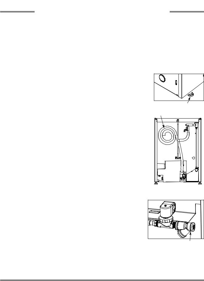
Adjustable Bullet Foot
Drain Hose
Back of Machine Showing Drain Hose
Incoming Plumbing Y-Strainer
PRESSURE REGULATOR: Do to areas where the water pressure fluctuates or is greater than the recommended pressure, it is recommended installing a water pressure regulator. Do not confuse static pressure with flow pressure. Static pressure is the line pressure in a “no flow” condition (all valves and services are closed). Flow pressure is the pressure in the fill line when the fill valve is opened during the cycle.
JPX-300 Technical Manual 7610-002-73-30 Rev. N
Issued: 03-06-2006 Revised: 9/15/2006
8
SECTION 2: INSTALLATION/OPERATION INSTRUCTIONS
ELECTRICAL INSTALLATION INSTRUCTIONS
SHOCK ABSORBER: It is also recommended that a shock absorber (not supplied with the JPX-300 series models) be installed in the incoming water line. This prevents line hammer (hydraulic shock), induced by the solenoid valve as it operates, from causing damage to the equipment.
CONNECTING THE DRAIN LINE: The JPX-300 series machines are a pumped (pressure) drain capable of pumping waste water to a height of 24 inches from the floor to the kitchen’s drain system. The dishmachines are supplied with a 10 foot long
hose that extends from the rear side of the machine. There must also be an air gap between the machine drain line and the |
||||
floor sink or drain. If a grease trap is required by code, it should have a flow |
|
|
||
capacity of 12 gallons per minute. |
|
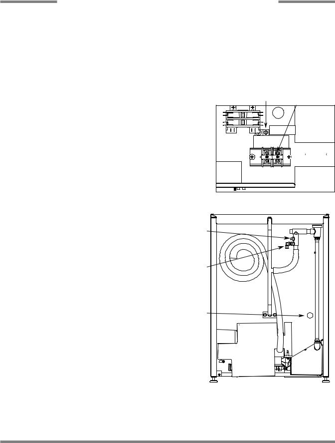
Ground Lug |
Terminal Block |
|
|
|
|||
PLUMBING CHECK: Slowly turn on the water supply to the machine after the |
|
|
||
incoming fill line and the drain line have been installed. Check for any leaks |
|
|
||
and repair as required. All leaks must be repaired prior to placing the machine |
|
|
||
in operation. |
|
|
|
|
ELECTRICAL POWER CONNECTION: Electrical and grounding connections |
|
|
||
must comply with the applicable portions of the National Electrical Code |
|
|
||
ANSI/NFPA 70 (latest edition) and/or other electrical codes. |
|
|
|
|
Disconnect electrical power supply and place a tag at the disconnect switch to |
|
|
||
indicate that you are working on the circuit. |
|
|
|
|
The dishmachine data plate is located on the front of the machine. Refer to the |
Control Box Electrical Connection |
|||
data plate for machine operating requirements, machine voltage, total amper- |
||||
|
|
|||
age load and serial number. |
|
|
|
|
To install the incoming power lines, remove the kick panel. |
|
|
|
|
This will require taking a phillips head screwdriver and |
Brass Plug |
|
|
|
removing the two screws at the bottom of the kick panel; |
|
|
|
|
open the door slightly while carefully lifting the kick panel |
|
|
|
|
up and out of the way. Install 3/4” conduit into the pre- |
|
|
|
|
punched holes in the back of the control box. Route power |
|
|
|
|
wires and connect to power block and grounding lug. |
Rinse Aid Fitting |
|
|
|
Install the service wires (L1 and L2) to the appropriate terminals as they are marked on the terminal block. Install the grounding wire into the lug provided. It is recommended that “DE-OX” or another similar anti-oxidation agent be used on all power connections.
VOLTAGE CHECK: Ensure that the power switch is in the |
Detergent Fitting |
|
|
OFF position and apply power to the dishmachine. Check |
|
the incoming power at the terminal block and ensure it cor- |
|
responds to the voltage listed on the data plate. If not, con- |
|
tact a qualified service agency to examine the problem. Do
not run the dishmachine if the voltage is too high or too low. Shut off the service breaker and mark it as being for the dishmachine. Advise all proper personnel of any problems and of the location of the service breaker. Replace the control box cover and tighten down the screws.
CHEMICAL CONNECTIONS: All chemical hookup locations are located on the back of the dishmachine. Please refer to the drawing at the right for the correct connection point. The JPX-300H/HC/HN dishmachines are supplied with integral detergent and rinse aid chemical feeder pumps. The JPX-300L
dishmachine is supplied with integral detergent, rinse additive and sanitizer chemical feeder pumps.
Please refer to page 11 for instructions on priming the chemical feeder pumps.
JPX-300 Technical Manual 7610-002-73-30 Rev. N
Issued: 03-06-2006 Revised: 9/15/2006
9

SECTION 2: INSTALLATION/OPERATION INSTRUCTIONS
CHEMICAL DISPENSING EQUIPMENT
WARNING: CHLORINE-BASED SANITIZERS CAN BE DETRIMENTAL TO YOUR MACHINE IF THE CHEMICAL SOLUTION IS TOO STRONG. SEE YOUR CHEMICAL PROFESSIONAL TO ENSURE YOUR DISPENSER IS SET UP CORRECTLY.
This equipment is not recommend for use with deionized water or other aggressive fluids. Use of deionized water or other aggressive fluids will result in corrosion and failure of materials and components. Use of deionized water or other aggressive fluids will void the manufacturer's warranty.
TO PREPARE CHEMICAL FEEDER PUMPS FOR OPERATION
The JPX-300H/HC/HN dishmachines are supplied with integral detergent and rinse aid chemical feeder pumps. The JPX-300L dishmachine is supplied with integral detergent, rinse additive and sanitizer chemical feeder pumps. Locate the open ends of the chemical tubes with the tube stiffeners and place each one in the appropriate container.
A.Red Tubing = Detergent
B.Blue Tubing = Rinse Aid
C.White Tubing = Sanitizer
PRIMING CHEMICAL FEEDER PUMPS
Chemical feeder pumps need priming when the machine is first installed or if for some reason the chemical lines have been removed and air is allowed to enter.
CAUTION: Water must be in the sump and wash tank prior to the dispensing of chemicals. Sanitizer in concentration is caustic and may cause damage without dilution.
1.Verify that the proper chemical tube stiffener inlet is in the proper container.
2.Use the prime switches located at the top of the unit to prime each pump. The switches are clearly marked (“D”, “R”, and “S”) as to what chemical feeder pump they are assigned to.
3.To prime the pumps, hold the switch in the momentary position until chemical can be observed entering the sump.
4.Detergent is dispensed as required during the wash cycle by the cam timer. The amount of detergent may need to be increased or decreased depending on water quality and type of detergent. It is adjusted by changing the detergent cam on the cam timer.
5.Rinse additive is dispensed as required into the final rinse. The amount of rinse aid may need to be adjusted depending on water hardness and results. It can be changed by changing the rinse cam on the cam timer.
6.Sanitizer (either chlorine or iodine) is dispensed into the final rinse. The amount of sanitizer may need to be adjusted depending on the concentration and type of sanitizer used. It is adjusted by changing sanitizer cam on the cam timer.
WARNING: Some of the chemicals used in dishwashing may cause chemical burns if they come in contact with your skin. Wear protective gear when handling these chemicals. If you do come in contact with these chemicals, immediately flush the affected area with fresh water.
JPX-300 Technical Manual 7610-002-73-30 Rev. N
Issued: 03-06-2006 Revised: N/A
10
SECTION 2: INSTALLATION/OPERATION INSTRUCTIONS
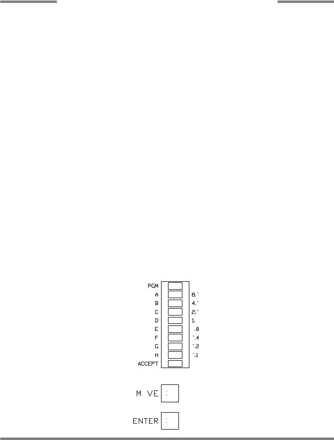
PROGRAMMING INSTRUCTIONS FOR CHEMICAL FEEDER PUMPS (FOR INSTALLATION TECHNICIAN ONLY)
To access the programming mode, the machine must be ON, and idle (between cycles).
On the timer board, press and hold both the MOVE and ENTER buttons on the timer board simultaneously for two seconds.
The PROGRAM (PGM) light and light A will illumniate.
Note: Once in the programming mode, the MOVE button is used to scroll between the programming categories and the ENTER button is used to select the category.
Press the MOVE button to move the solid light to the desired location of FILL, RINSE AID, DETERGENT or SANITIZER. Please note that options A, B, C, and D are not adjustable outputs.
Press the ENTER button for the chosen category. Now, the (PGM) light will illuminate along with lights corresponding to the time values forthe chosen category. The ACCEPT light will blink.
The PROGRAM light will illuminate.
To change the value of a parameter, use the MOVE button to illuminate the light next to the time option (time is in seconds). In the time categories, each second in use will light up. To deselect the option, press ENTER and the light will go off, press ENTER again and it will illuminate. Once you have set your time category, press the MOVE button until the ACCEPT light illuminates and press ENTER. This will save the changed parameters.
Once you press the ENTER button when the ACCEPT light is blinking you will exit the programming mode. To change any other values, you will have to return to the programming mode. To revert back to a previous setting, you must return to that option and change the parameter back to the previous setting.
Once in the programming mode, if there have been no keypad inputs for approximately 2 minutes, the system will automatically exit out of the programming mode. Any changes to parameters will be saved when the programming mode is automatically exited.
The wash and drain settings are not adjustable.
All time adjustments are in seconds. Refer to the chart below for the adjustable outputs.
Timer Programming Board
Time in seconds.
JPX-300H |
JPX-300L |
||
|
|
|
|
Not adjustable |
Rinse Aid |
||
|
|
|
|
Rinse |
Fill |
||
|
|
|
|
Detergent |
Sanitizer |
||
|
|
|
|
Rinse Aid |
Detergent |
||
|
|
|
|
|
|
|
|
JPX-300 Technical Manual 7610-002-73-30 Rev. N
Issued: 03-06-2006 Revised: 03-07-2007
11

SECTION 2: INSTALLATION/OPERATION INSTRUCTIONS
DETERGENT CONTROL
Detergent usage and water hardness are two factors that contribute greatly to how efficiently your dishmachine will operate. Using detergent in the proper amount can become, in time, a source of substantial savings. A qualified water treatment specialist can tell you what is needed for maximum efficiency from your detergent, but you should still know some basics so you’ll understand what they are talking about.
First, you must understand that hard water greatly effects the performance of the dishmachine. Water hardness is the amount of dissolved calcium and magnesium in the water supply. The more dissolved solids in the water, the greater the water hardness. Hard water works against detergent, thereby causing the amount of detergent required for washing to increase. As you use more detergent, your costs for operating the dishmachine will increase and the results will decrease. The solids in hard water also may build-up as a scale on wash and rinse heaters, decreasing their ability to heat water. Water temperature is important in removing soil and sanitizing dishes. If the water cannot get hot enough, your results may not be satisfactory. This is why Jackson recommends that if you have installed the machine in an area with hard water, that you also install some type of water treatment equipment to help remove the dissolved solids from the water before it gets to the dishmachine.
Second, hard water may have you adding drying agents to your operating cycle to prevent spotting, when the real problem is deposited solids on your ware. As the water evaporates off of the ware, the solids will be left behind to form the spotting and no amount of drying agent will prevent this. Again, using treated water will undoubtedly reduce the occurrences of this problem.
Third, treated water may not be suitable for use in other areas of your operation. For instance, coffee made with soft water may have an acid or bitter flavor. It may only be feasible to install a small treatment unit for the water going into the dishmachine itself. Discuss this option with your qualified water treatment specialist.
Even after the water hardness problems have been solved, there still must be proper training of dishmachine operators in how much detergent is to be used per cycle. Talk with your water treatment specialist and detergent vendor and come up with a complete training program for operators. Using too much detergent has as detrimental effects as using too little. The proper amount of detergent must be used for job. It is important to remember that certain menu items may require extra detergent by their nature and personnel need to be made aware of this. Experience in using the dishmachine under a variety of conditions, along with good training in the operation of the machine, can go a long way in ensuring your dishmachine operates as efficiently as possible.
Certain dishmachine models require that chemicals be provided for proper operation and sanitization. Some models even require the installation of third-party chemical feeders to introduce those chemicals to the machine. Jackson does not recommend or endorse any brand name of chemicals or chemical dispensing equipment. Contact your local chemical distributor for questions concerning these subjects.
Some dishmachines come equipped with integral solid detergent dispensers. These dispensers are designed to accommodate detergents in a certain sized container. If you have such a unit, remember to explain this to your chemical distributor upon first contacting them.
As explained before, water temperature is an important factor in ensuring that your dishmachine functions properly. The data plate located on each unit details what the minimum temperatures must be for either the incoming water supply, the wash tank and the rinse tank, depending on what model of dishmachine you have installed. These temperatures may also be followed by temperatures that Jackson recommends to ensure the highest performance from you dishmachine. However, if the minimum requirements are not met, the chances are your dishes will not be clean or sanitized. Remember, a dish can look clean, but it may not be sanitized. Instruct your dishmachine operators to observe the required temperatures and to report when they fall below the minimum allowed. A loss of temperature can indicate a much larger problem such as a failed heater or it could also indicate that the hot water heater for your operation is not up to capacity and a larger one may need to be installed.
There are several factors to consider when installing your dishmachine to ensure that you get the best possible results from it and that it operates at peak efficiency for many years. Discuss your concerns with your local chemical distributor and water treatment specialist before there is a problem.
JPX-300 Technical Manual 7610-002-73-30 Rev. N
Issued: 03-06-2006 Revised: N/A
12

SECTION 2: INSTALLATION/OPERATION INSTRUCTIONS
OPERATION INSTRUCTIONS
PREPARATION: Before proceeding with the start-up of the unit, verify the following:
1.The strainer is in place and is clean.
2.That the wash and rinse arms are screwed securely into place and that their endcaps are tight. The wash and rinse arms should rotate freely.
3.Verify all chemical levels for machine chemical feeder pumps are correct.
POWER UP: To energize the unit, turn on the power at the service breaker. The voltage should have been previously verified as being correct. If not, the voltage will have to be verified.
FILLING THE WASH TUB: For the initial fill, close the door and ensure that the MANUAL switch light is not on. Depress and hold the START CYCLE switch until the auto light comes on and releases. For the initial fill, run the machine through 3 cycles to fill the tub sump. The machine will run a partial cycle and fill to the bottom of the pan strainer. Open the door and verify that the water level is correct.
NOTE: For the JPX-300H/JPX-300HC: Ensure the orange/white wires at the heater contactor are connected properly. They have been purposely disconnected at the factory to avoid damage to the heater element when there is no water in the booster heater.
Hereafter, the water level is controlled by the timer that has been preset at the factory. Verify that there are no other leaks on the unit before proceeding any further. The wash sump must be completely filled before operating the wash pump to prevent damage to the component. Once the wash tub is filled, the unit is ready for operation.
The machine runs a complete cycle to drain and fill. If the machine is not allowed to drain, the water will build up inside the tub. After the initial fill, the rinse water for the current cycle will become the wash water for the next cycle.
WARE PREPARATION: Proper preparation of ware will help ensure good results and less re-washes. If not done properly, ware may not come out clean and the efficiency of the dishmachine will be reduced. It is important to remember that a dishmachine is not a garbage disposal and that simply throwing unscraped dishes into the machine simply defeats the purpose altogether of washing the ware. Scraps should be removed from ware prior to being loaded into a rack. Pre-rinsing and pre-soaking are good ideas, especially for silverware and casserole dishes. Place cups and glasses upside down in racks so that they do not hold water during the cycle. The dishmachine is meant not only to clean, but to sanitize as well, to destroy all of the bacteria that could be harmful to human beings. In order to do this, ware must be properly prepared prior to being placed in the machine.
DAILY MACHINE PREPARATION: Refer to the section entitled “PREPARATION” at the top of this page and follow the instructions there. Afterwards, check that all of the chemical levels are correct and/or that there is plenty of detergent available for the expected workload.
WARM-UP CYCLES: For a typical daily start-up, it is recommended to run the machine through 3 cycles to ensure that all of the cold water is out of the system and to verify that the unit is operating correctly. To cycle the machine, ensure that the power is on and that the tub has filled to the correct level.
Press the START CYCLE button and hold until the green auto light is on and releases, the unit will start, run through the cycle, and shut off automatically. Repeat this two more times. The unit should now be ready to proceed with the washing of ware.
WASHING A RACK OF WARE: To wash a rack, open the door completely and slide the rack into the unit. Close the door, press the START CYCLE button and hold until the green auto light is on and releases, the unit will start. Once the cycle is completed, open the door and remove the rack of clean ware. Replace with a rack of soiled ware and close the door. The process will then repeat itself.
OPERATIONAL INSPECTION: Based upon usage, the pan strainer may become clogged with soil and debris as the workday progresses. Operators should regularly inspect the pan strainer to ensure it has not become clogged. If the strainer does, it will reduce the washing capability of the machine. Instruct operators to clean out the pan strainer at regular intervals or as required by work load.
JPX-300 Technical Manual 7610-002-73-30 Rev. N
Issued: 03-06-2006 Revised: N/A
13

SECTION 2: INSTALLATION/OPERATION INSTRUCTIONS
OPERATION INSTRUCTIONS (CONTINUED)/DELIMING INSTRUCTIONS
SHUTDOWN AND CLEANING: At the end of the workday, close the door. Start a cycle. Wait approximately five seconds after the green auto light comes on and then push the POWER OFF switch. This will put the machine in shutdown mode which will let the machine drain completely prior to shutting off. Once the wash tub is drained and power light is off, remove he pan strainer. Remove soil and debris from the strainer and set to the side. Unscrew the wash and rinse arms from their manifolds. Remove the endcaps and flush the arms with water. Use a brush to clean out the inside of the arms. If the nozzles appear to be clogged, use a toothpick to remove the obstruction. Wipe the inside of the unit out, removing all soil and scraps. Reassemble the wash and rinse arms and replace them in the unit. The arms only need to be hand tight, do not use tools to tighten them down. Reinstall the strainer and close the door.
DELIMING OPERATIONS: In order to maintain the dishmachine at its optimum performance level, it will be required to remove lime and corrosion deposits on a frequent basis. A deliming solution should be available from your detergent supplier. Read and follow all instructions on the label of the deliming solution.
NOTE: If this machine is equipped with a HTS-11, scale prevention and corrosion control device, and lime is becoming a frequent problem, the cartridge needs to be replaced. To order a replacement cartridge (4730-003-28-04), call Jackson immediately to have one shipped to you.
To proceed with the deliming operation, fill the dishmachine and add the correct amount of deliming solution as recommended by the deliming solution manufacturer. The water capacity of the tank can be verified on the specification sheet(s) of this manual.
Perform the following operations to delime the dishmachine:
1.Push Manual Switch on the front of the control panel.
2.Disconnect or turn off all chemical feeder pumps.
3.Close all doors (after adding the deliming solution).
4.Run the machine for the recommended period of time.
5.Press the Power Switch to turn the unit off and open the doors.
6.Wait five minutes, then inspect the inside of the machine. If the machine is not delimed, run another time cycle as per the deliming solution’s instructions.
7.When clean, drain and re-fill the machine.
8.Run in MANUAL for 10 minutes to remove residual deliming solution.
9.Drain and re-fill the machine.
JPX-300 Technical Manual 7610-002-73-30 Rev. N
Issued: 03-06-2006 Revised: N/A
14
SECTION 3:
PREVENTATIVE MAINTENANCE
15

SECTION 3: PREVENTATIVE MAINTENANCE
PREVENTATIVE MAINTENANCE
The dishmachines covered in this manual are designed to operate with a minimum of interaction with the operator. However, this does not mean that some items will not wear out in time. Jackson highly recommends that any maintenance and repairs not specifically discussed in this manual should be performed by QUALIFIED SERVICE PERSONNEL ONLY. Performing maintenance on your dishmachine may void your warranty if it is still in effect.
There are many things that operators can do to prevent catastrophic damage to the dishmachine. One of the major causes of component failure has to do with prescrapping procedures. A dishmachine is not a garbage disposal; any large pieces of material that are put into the machine shall remain in the machine until they are either broken up (after spreading out on your ware!) or physically removed. Strainers are installed to help catch debris, but they do no good if they are clogged. Have operators regularly inspect the pan strainers to ensure (1) that they are free of soil and debris and (2) they are laying flat in the tub.
When cleaning out strainers, do NOT beat them on waste cans. The strainers are made of metal and can be forgiving; but once severe damage is done, it is next to impossible for the strainer to work in the way it was designed to. Wipe out strainers with a rag and rinse under a faucet if necessary. For stubborn debris, a toothpick should be able to dislodge any obstructions from the perforations. Always ensure that strainers are placed back in the machine before operation and that they lay flat in the tub.
You may wish to also refer to the page entitled “Detergent Control” in order to learn more about how your water hardness will effect the performance of your machine. Hard water makes dishmachines work harder and decreases efficiency.
Again, it is important to remind operators that trying to perform corrective maintenance on the dishmachine could lead to larger problems or even cause harm to the operator. If a problem is discovered; secure the dishmachine using proper shut down procedures as listed in this manual and contact a QUALIFIED SERVICE AGENCY.
Some problems, however, may having nothing to do with the machine itself and no amount of preventative maintanence is going to help. A common problem has to do with temperatures being too low. Verify that the water temperatures coming to your dishmachine match the requirements listed on the machine data plate. There can be a variety of reasons why your water temperature could be too low and you should discuss it with a QUALIFIED SERVICE AGENCY to determine what can be done.
By following the operating and cleaning instructions in this manual, you should get the most efficient results from your machine. As a reminder, here are some steps to take to ensure that you are using the dishmachine the way it was designed to work:
1.Ensure that the water temperatures match those listed on the machine data plate.
2.Ensure that all strainers are in place before operating the machine.
3.Ensure that all wash and/or rinse arms are secure in the machine before operating.
4.Ensure that drains are closed/sealed before operating.
5.Remove as much soil from dishes by hand as possible before loading into racks.
6.Do not overfill racks.
7.Ensure that glasses are placed upside down in the rack.
8.Ensure that all chemicals being injected to machine have been verified as being at the correct concentrations.
9.Clean out the machine at the end of every workday as per the instructions in the manual.
10.Always contact a QUALIFIED SERVICE AGENCY whenever a serious problem arises.
11.Follow all safety procedures, whether listed in this manual or put forth by local, state or national codes/regulations.
JPX-300 Technical Manual 7610-002-73-30 Rev. N
Issued: 03-06-2006 Revised: N/A
16

SECTION 4:
TROUBLESHOOTING
17

SECTION 4: TROUBLESHOOTING SECTION
COMMON PROBLEMS
WARNING: Inspection, testing and repair of electrical equipment should be performed only by qualified service personnel. Certain procedures in this section require electrical tests or measurements while power is applied to the machine. Exercise extreme caution at all times. If test points are not easily accessible, disconnect power, attach test equipment and reapply power to test. When replacing electrical parts, disconnect power at source circuit breaker.
Problem: Water overflow from bottom of door.
1.Clogged drain. Remove obstruction.
2.Machine not level. Level machine, or increase height to the front.
3.Excessive inlet pressure. Install pressure reducing valve, or adjust if one is present. Ensure flow is 20 ±5 PSI.
4.Detergent foaming. Reduce detergent quantity.
5.C4 Microswitch is stuck closed. Replace.
Problem: Wash motor doesn’t operate on manual wash.
1.Loose or broken wires. Reconnect or replace wires in motor.
2.Defective manual wash switch. Replace.
3.Defective motor starting relay. Replace.
Problem: Motor operates on manual wash but not on automatic.
1.C1 timer microswitch is defective. Replace.
2.C2 timer microswitch is defective. Replace.
3.Defective circuit in manual wash switch. Replace switch.
Problem: No water comes through the rinse arms when the “ON/FILL” switch is depressed.
1.Water not turned on. Turn water on.
2.Defective solenoid valve. Replace solenoid valve.
Problem: Little or no water coming through the rinse assemblies.
1.Limed up rinse heads or piping. Delime rinse heads.
2.Low water pressure. Increase pipe size to machine. Adjust pressure regulator.
Problem: Rinse water runs continuously with breaker turned off.
1.Defective plunger in solenoid valve. Replace.
2.Defective diaphragm in solenoid valve. Replace diaphragm.
Problem: Rinse doesn’t operate on automatic during timed cycle (but does operate in auto/fill operation).
1. C4 microswitch is defective. Replace.
Problem: Rinse water runs continuously with power applied to machine, but when circuit breaker to machine is turned off, water stops.
1. C4 timer microswitch is stuck closed. Replace.
Problem: Wash temperature not at required reading on thermometer.
1.Check that orange/white wires are connected. See note on page 12.
2.Defective thermometer. Replace.
3.Defective thermostat. Adjust thermostat. Replace thermostat.
4.Rinse or strip heater defective. Replace heater element.
5.Defective heater contactor R1. Replace.
JPX-300 Technical Manual 7610-002-73-30 Rev. N
Issued: 03-06-2006 Revised: N/A
18

SECTION 4: TROUBLESHOOTING SECTION
COMMON PROBLEMS
WARNING: Inspection, testing and repair of electrical equipment should be performed only by qualified service personnel. Certain procedures in this section require electrical tests or measurements while power is applied to the machine. Exercise extreme caution at all times. If test points are not easily accessible, disconnect power, attach test equipment and reapply power to test. When replacing electrical parts, disconnect power at source circuit breaker.
Problem: Rinse water not at required temperature range.
1.Check that orange/white wires are connected. See note on page 12.
2.Thermometer is defective. Replace.
3.Thermostat is defective. Adjust the thermostat. Replace if necessary.
4.Incoming rinse water does not meet minimum criteria indicated on machine data plate. Adjust as required.
Problem: Machine doesn’t drain when “OFF/DRAIN” switch is pressed.
1.Drain solenoid clogged. Remove obstruction.
2.Defective motor or motor start relay. Replace.
3.Defective drain valve. Replace.
4.Defective C5 microswitch. Replace.
Problem: No indication of pressure.
1.Water turned off. Turn water on.
2.1/4” test cock ball valve is closed. Open the ball valve.
3.Pressure gauge defective. Replace pressure gauge.
JPX-300 Technical Manual 7610-002-73-30 Rev. N
Issued: 03-06-2006 Revised: N/A
19
 Loading...