


I |
AJ-66 SERIES RACK CONVEYOR DISHMACHINES |
N |
(ELECTRICALLY HEATED) |
S |
|
T |
|
A |
|
L |
|
L |
|
A |
|
T |
MODELS COVERED IN THIS MANUAL: |
I |
|
O |
|
N |
AJ-66CE |
|
|
& |
AJ-66CEL |
O |
MODELS FOR EXPORT ONLY |
P |
|
E |
|
R |
|
A |
|
T |
|
I |
|
O |
|
N |
|
M |
|
A |
|
N |
|
U |
|
A |
|
L |
|
September 28, 2001 |
|
P/N 7610-002-43-26 (Revision A) |
www.jacksonmsc.com |

TABLE OF CONTENTS
SECTION |
DESCRIPTION |
PAGE |
I.GENERAL SECTION
Specifications |
1 |
II.INSTALLATION & OPERATION SECTION
|
Installation Instructions |
2 |
|
Operating Instructions |
3 |
III. |
TROUBLESHOOTING SECTION |
4 |
IV. |
DIMENSIONS |
6 |
V. |
PARTS SECTION |
|
|
AJ-66 Single Phase Control Box Assembly |
8 |
|
AJ-66 Three Phase Control Box Assembly |
10 |
|
Motor Overloads |
12 |
|
Heater Box Assembly |
13 |
|
Heater Box Cover/Thermostats |
16 |
|
Wash Section Incoming Plumbing Assembly |
17 |
|
Prewash Section Incoming Plumbing Assembly |
18 |
|
AJ-66 (Left to Right) Drain Plumbing Assembly |
19 |
|
AJ-66 (Right to Left) Drain Plumbing Assembly |
20 |
|
Drain Handle Weldment Assembly/Frame Weldment |
21 |
|
Motors/Motor Support Bracket Assembly |
22 |
|
Wash Pump Assembly |
23 |
|
Wash Pump Weldment |
24 |
|
Prewash Pump Weldment |
25 |
|
Assorted Gaskets |
26 |
|
Wash Heaters/Hood Weldments/Tub Weldments |
27 |
|
Wash Manifold, Prewash Manifold & Strainer Support Weldments |
28 |
|
Upper Wash Arm Assembly |
29 |
|
Lower Wash Arm Assembly |
30 |
|
Prewash Arm Assembly |
31 |
|
Final Rinse Assembly |
32 |
|
Rinse Tray Assembly |
33 |
|
Drive Assembly |
34 |
|
Lubrication Chart for Gear Drive |
37 |
|
Drive Motor Gear Reducer Preventative Maintenance |
38 |
|
Wash Door and Vent Cowl Assembly |
39 |
|
Miscellaneous Door Assemblies |
40 |
|
AJ-66 (Left to Right) Rack Rail Assembly |
41 |
|
AJ-66 (Right to Left) Rack Rail Assembly |
42 |
|
Accuator Assemblies |
43 |
|
Pawl Bar Roller Bracket |
44 |
|
AJ-66 Pawl Bar Assembly |
45 |
|
Miscellaneous Parts and Weldments |
46 |
|
Strainers |
49 |
|
Float Switch Assembly |
50 |
|
Dress Panel |
51 |
|
Magnet Switch Assemblies |
52 |
|
Curtains |
53 |
|
208 Volt/230 Volt - 50/60 Hz - Single Phase Schematic |
54 |
|
208 Volt/220 Volt/230 Volt - 50/60 Hz - Three Phase Schematic |
55 |
|
380 Volt/460 Volt/600 Volt - 60 Hz - Three Phase Schematic |
56 |
|
380 Volt/415 Volt/440 Volt - 50 Hz - Three Phase Schematic |
57 |
i

|
|
|
|
Drive Motor |
Prewash Motor |
Wash Motor |
Heater Load |
Total |
||||
Model |
Volts |
Phase |
Hz |
HP |
Amps |
HP |
Amps |
HP |
Amps |
KW |
Amps |
Amps |
AJ-66CE/CEL |
208 |
1 |
60 |
1/4 |
1.8 |
1 |
6 |
2 |
8.5 |
15 |
72 |
88.3 |
AJ-66CE/CEL |
230 |
1 |
60 |
1/4 |
1.8 |
1 |
6 |
2 |
8.5 |
15 |
65.2 |
81.5 |
AJ-66CE/CEL |
200 |
3 |
60 |
1/4 |
1.1 |
1 |
3.4 |
2 |
5.6 |
13.9 |
40.1 |
50.2 |
AJ-66CE/CEL |
208 |
3 |
60 |
1/4 |
1.1 |
1 |
3.4 |
2 |
5.6 |
15 |
41.7 |
51.8 |
AJ-66CE/CEL |
230 |
3 |
60 |
1/4 |
1.1 |
1 |
3.4 |
2 |
5.6 |
15 |
37.7 |
47.8 |
AJ-66CE/CEL |
380 |
3 |
60 |
1/4 |
0.55 |
1 |
1.8 |
3 |
5.1 |
15 |
22.8 |
30.3 |
AJ-66CE/CEL |
460 |
3 |
60 |
1/4 |
0.55 |
1 |
1.7 |
2 |
2.8 |
15 |
18.8 |
23.9 |
AJ-66CE/CEL |
600 |
3 |
60 |
1/4 |
0.46 |
2 |
2.8 |
2 |
2.8 |
16.3 |
15.7 |
21.8 |
|
|
|
|
|
|
|
|
|
|
|
|
|
|
|
|
|
|
|
|
|
|
|
|
|
|
|
|
|
|
|
|
|
Drive Motor |
|
Prewash Motor |
Wash Motor |
Heater Load |
Total |
|
|
|||||||
|
|
|
|
Model |
Volts |
Phase |
Hz |
|
HP |
|
Amps |
|
HP |
|
Amps |
HP |
Amps |
KW |
|
Amps |
Amps |
|
|
|
|
|
|
AJ-66CE/CEL |
208 |
3 |
50 |
|
1/3 |
|
0.6 |
|
1 |
|
3.6 |
3 |
12 |
15 |
|
41.7 |
57.9 |
|
|
|
|
|
|
AJ-66CE/CEL |
220 |
3 |
50 |
|
1/3 |
|
0.6 |
|
1 |
|
3.6 |
3 |
12 |
13.7 |
|
36 |
52.2 |
|
|
|
|
|
|
AJ-66CE/CEL |
230 |
3 |
50 |
|
1/3 |
|
0.6 |
|
1 |
|
3.6 |
3 |
12 |
15 |
|
37.7 |
53.9 |
|
|
|
|
|
|
AJ-66CE/CEL |
380 |
3 |
50 |
|
1/3 |
|
0.6 |
|
1 |
|
1.8 |
3 |
5.1 |
15 |
|
22.8 |
30.3 |
|
|
|
|
|
|
AJ-66CE/CEL |
415 |
3 |
50 |
|
1/3 |
|
0.6 |
|
3 |
|
6 |
3 |
6 |
15 |
|
20.9 |
33.5 |
|
|
1 |
|
|
|
AJ-66CE/CEL |
440 |
3 |
50 |
|
1/3 |
|
0.6 |
|
3 |
|
5 |
3 |
5 |
16.8 |
|
22.1 |
32.7 |
|
|
|
|
RACKS PER HOUR: |
|
|
|
|
|
PREWASH PUMP CAPACITY (GPM): |
|
WATER TEMPERATURES (°F): |
|
|
|
||||||||||
|
|
|
|
|
|
|
|
|
|
|
|
||||||||||||
|
|
|
|
|
|
|
|
|
|
|
|
||||||||||||
|
|
AJ-66CE: |
|
|
|
248 |
|
|
|
|
|||||||||||||
|
|
|
|
|
|
|
|
|
|
|
|
|
|
|
|
|
|
|
|||||
|
|
AJ-66CEL: |
|
|
|
234 |
ALL MODELS: |
|
|
|
120 |
CE MODELS: |
|
|
|
|
|||||||
|
|
DISHES OR GLASSES PER HOUR: |
|
|
|
VENTING REQUIREMENTS (CFM)(100% CAP.): |
PREWASH (MINIMUM) |
110 |
|
||||||||||||||
|
|
|
|
|
|
|
|
|
|
|
|
|
|
|
|
|
WASH (MINIMUM) |
|
160 |
|
|||
|
|
AJ-66CE: |
|
|
|
6200 |
INPUT END: |
|
|
|
200 |
RINSE (MINIMUM) |
|
180 |
|
||||||||
|
|
AJ-66CEL: |
|
|
|
5850 |
OUTPUT END: |
|
|
|
400 |
CEL MODELS: |
|
|
|
|
|||||||
|
|
|
|
|
|
|
|
|
|
TOTAL: |
|
|
|
600 |
|
|
|
|
|||||
|
|
WASH TANK CAPAITY (GALLONS): |
|
|
|
CONVEYOR SPEED (FPM): |
|
|
PREWASH (MINIMUM) |
110 |
|
||||||||||||
|
|
|
|
|
|
|
|
|
|
|
|
|
|
|
|
|
PREWASH (RECOMMENDED) |
140 |
|
||||
|
|
ALL MODELS: |
|
|
|
15.4 |
CE MACHINES: |
|
|
|
6.9 |
WASH (MINIMUM) |
|
140 |
|
||||||||
|
|
PREWASH TANK CAPACITY (GALLONS): |
|
|
CEL MACHINES: |
|
6.5 |
RINSE (MINIMUM) |
|
140 |
|
||||||||||||
|
|
|
|
GALLONS PER RACK: |
|
|
FLOW PRESSSURE (PSI) |
20 |
|
||||||||||||||
|
|
ALL MODELS: |
|
|
|
16 |
|
|
|
||||||||||||||
|
|
|
|
|
CE MACHINES: |
|
|
|
.94 |
FLOWRATE (GPM) |
|
3.9 |
|
||||||||||
|
|
WASH PUMP CAPACITY: |
|
|
|
|
|
|
|
|
|
||||||||||||
|
|
|
|
|
|
CEL MACHINES: |
|
1.00 |
MINIMUM CHLORINE (PPM) |
50 |
|
||||||||||||
|
|
|
|
|
|
|
|
|
|
|
|
|
|
|
|
|
|
||||||
|
|
GALLONS PER MINUTE: |
|
|
270 |
|
|
|
|
|
|
|
(CEL MODELS ONLY) |
|
|
|
|
||||||
|
|
|
|
|
|
|
|
|
|
|
|
|
|
|
|
|
|
|
|
|
|
|
|
SPECIFICATIONS

INSTALLATION INSTRUCTIONS
Jackson MSC Inc. provides technical support for all of the dishmachines detailed in this manual. We strongly recommend that you refer to this manual before making a call to our technical support staff. Please have this manual with you when you call so that our staff can refer you, if necessary, to the proper page. Technical support is avaliable from 8:00 a.m. to 5:00 p.m. (EST), Monday through Friday. Technical support is not available on holidays. Contact technical support toll-free at 1-888-800-5672. Please remember that technical support is available for service personnel only.
VISUAL INSPECTION: Before installing the unit, check the container and machine for damage. A damaged container is an indicator that there may be some damage to the machine. If there is damage to both the container and machine, do not throw away the container. The dishmachine has been inspected and packed at the factory and is expected to arrive to you in new, undamaged condition. However, rough handling by carriers or others may result in there being damage to the unit while in transit. If such a situation occurs, do not return the unit to Jackson; instead, contact the carrier and ask them to send a representative to the site to inspect the damage to the unit and to complete an inspection report. You must contact the carrier within 48 hours of receiving the machine. Also, contact the dealer through which you purchased the unit.
UNPACKING THE DISHMACHINE: Once the machine has been removed from the container, ensure that there are no missing parts from the machine. This may not be obvious at first. If it is discovered that an item is missing, contact Jackson immediately to have the missing item shipped to you.
LEVEL THE DISHMACHINE: The dishmachine is designed to operate while being level. This is important to prevent any damage to the machine during operation and to ensure the best results when washing ware. The unit comes with adjustable bullet feet, which can be turned using a pair of channel locks or by hand if the unit can be raised safely. Ensure that the unit is level from side to side and from front to back before making any connections.
PLUMBING THE DISHMACHINE: All plumbing connections must comply with all applicable local, state, and national plumbing codes. The plumber is responsible for ensuring that the incoming water line is throroughly flushed prior to connecting it to any component of the dishmachine. It is necessary to remove all foreign debris from the water line that may potentially get trapped in the valves or cause an obstruction. Any valves that are fouled as a result of foreign matter left in the water line, and any expenses resulting from this fouling, are not the responsibility of the manufacturer.
CONNECTING THE DRAIN LINE: The drain for the models covered in this manual are gravity disharge drains. All piping from the 1-1/2” MNPT connection must be pitched (1/4” per foot) to the floor or sink drain. All piping from the machine to the drain must be a minimum 1-1/2” I.P.S. and shall not be reduced. There must also be an air gap between the machine drain line and the floor sink or drain. If a grease trap is required by code, it should have a flow capacity of 30 gallons per minute.
WATER SUPPLY CONNECTION: Ensure that you have read the section entitled “PLUMBING THE DISHMACHINE” above before proceding. Install the water supply line (3/4” pipe size minimum) to the dishmachine line strainer using copper pipe. It is recommended that a water shut-off valve be installed in the water line between the main supply and the machine to allow access for service. The water supply line is to be capable of 25 PSI “flow” pressure at the recommended temperature indicated on the data plate.
In areas where the water pressure fluctuates or is greater than the recommended pressure, it is suggested that a water pressure regulator be installed. The models covered in this manual do not come with water pressure regulators as standard equipment.
Do not confuse static pressure with flow pressure. Static pressure is the line pressure in a “no flow” condition (all valves and services are closed).
Flow pressure is the pressure in the fill line when the fill valve is opened during the cycle.
It is also recommended that a shock absorber (not supplied) be installed in the incoming water line. This prevents line hammer (hydraulic shock), induced by the solenoid valve as it operates, from causing damage to the equipment.
PLUMBING CHECK: Slowly turn on the water supply to the machine after the incoming fill line and the drain line have been installed. Check for any leaks and repair as required. All leaks must be repaired prior to placing the machine in operation.
ELECTRICAL POWER CONNECTION: Electrical and grounding connections must comply with the applicable portions of the National Electrical
Code ANSI/NFPA 70 (latest edition) and/or other electrical codes.
Disconnect electrical power supply and place a tag at the disconnect switch to indicate that you are working on the circuit.
The dishmachine data plate is located on the right side and to the front of the machine. Refer to the data plate for machine operating requirements, machine voltage, total amperage load and serial number.
To install the incoming power lines, open the control box. Install conduit into the pre-punched holes in the back of the control box. Route power wires and connect to power block and grounding lug. Install the service wires (L1, L2, and L3 (3 phase only)) to the appropriate terminals as they are marked on the terminal block. Install the grounding wire into the lug provided. Tighten the connections. It is recommended that “DE-OX” or another similar anti-oxidation agent be used on all power connections.
VOLTAGE CHECK: Ensure that the power switch is in the OFF position and apply power to the dishmachine. Check the incoming power at the terminal block and ensure it corresponds to the voltage listed on the data plate. If not, contact a qualified service agency to examine the problem. Do not run the dishmachine if the voltage is too high or too low. Shut off the service breaker and mark it as being for the dishmachine. Advise all proper personnel of any problems and of the location of the service breaker. Replace the control box cover and tighten down the screws.
VENTILATION OF DISHMACHINE: The dishmachine should be located with provisions for venting into an adequate exhaust hood or ventilation system. This is essential to permit efficient removal of the condensation exhaust. Ensure that the exhaust system is acceptable in accordance with all applicable codes and standards.
NOTE: Damage caused by steam or moisture due to improper ventilation is NOT covered under the warranty.
This units covered in this manual have the following exhaust requirements:
Load End: |
200 CFM |
Unload End: |
400 CFM |
The exhaust system must be sized to handle this volume for the dishmachine to operate as it was designed to.
ELECTRIC HEAT: The thermostats for the machines covered in this manual are factory set. They should not be adjusted except by an authorized service agent.
2

INSTALLATION INSTRUCTIONS (CONTINUED)/OPERATING INSTRUCTIONS
CHEMICAL FEEDER EQUIPMENT: The AJ-66CEL is designed to operate with a third party chemical injection system. Jackson does not endorse any particular chemical injection system. The system selected must be able to provide detergent and sanitizer in the required concentrations. The minimum chlorine concentration for proper sanitization is 50 PPM.
Furthermore, the selected feeder needs to be able to operate against a head of 25 PSI and deliver 7.38 ml of a 10% chlorine sanitizer per minute.
Detergent may be introduced into the unit through the removal of the bulkhead plug in the rear of the tub and replacing it with the third party detergent injection fitting. Remove the bulkhead plug in the side of the tub to install the detergent concentration probe.
The 1/8” brass plugs on the incoming plumbing rinse injector may be removed to install sanitizer and rinse aid injection fittings.
All wires for the chemical injectors should be routed through the back of the control box.
Terminals in the control box marked “CVS” provide a constant voltage signal whenever the drive motor is operating.
Terminals in the control box marked “DET” provide a voltage signal whenever the wash motor is operating.
DELIMING OPERATIONS: In order to maintain the dishmachine at its optimum performance level, it will be required to remove lime and corrosion deposits on a frequent basis. A deliming solution should be available from your detergent supplier. Read and follow all instructions on the label of the deliming solution.
To proceed with the deliming operation, fill the dishmachine and add the correct amount of deliming solution as recommended by the deliming solution manufacturer. The water capacity of the various tanks of the dishmachine can be verified on the specification sheet(s) of this manual.
Perform the following operations to delime the dishmachine:
1.Turn the NORMAL/DELIME switch on the back of the control box to the DELIME position.
2.Disconnect or turn off all chemical feeder pumps.
3.Close all doors (after adding the deliming solution).
4.Run the machine for the recommended period of time.
5.Turn the unit off and open the doors.
6.Wait five minutes, then inspect the inside of the machine. If the machine is not delimed, run another time cycle as per the deliming solution’s instructions.
7.When clean, drain and re-fill the machine.
8.Run in MANUAL for 10 minutes to remove residual deliming solution.
9.Drain and re-fill the machine.
OPERATING INSTRUCTIONS
PREPARATION: Before proceeding with the start-up of the unit, verify the following:
1.Close door(s) on dishmachine.
2.Close the drain valve(s).
POWER UP: To energize the unit, turn on the power at the service breaker. The voltage should have been previously verified as being correct. If not, the voltage will have to be verified.
FILLING THE WASH TUB: Ensure that the delime switch is in the NOR-
MAL position, and place the power switch into the ON position. The machine should fill automatically and shut off when the appropriate level is reached (just below the pan strainer). The wash tub must be completely filled before operating the wash pump to prevent damage to the component. Once the wash tub is filled, the unit is ready for operation.
WARE PREPARATION: Proper preparation of ware will help ensure good results and less re-washes. If not done properly, ware may not come out clean and the efficiency of the dishmachine will be reduced. It is important to remember that a dishmachine is not a garbage disposal and that simply throwing unscrapped dishes into the machine simply defeats the purpose altogether of washing the ware. Scraps should be removed from ware prior to being loaded into a rack. Pre-rinsing and pre-soaking are good ideas, especially for silverware and casserole dishes. Place cups and glasses upside down in racks so that they do not hold water during the cycle. The dishmachine is meant not only to clean, but to sanitize as well, to destroy all of the bacteria that could be harmful to human beings. In order to do this, ware must be properly prepared prior to being placed in the machine.
DAILY MACHINE PREPARATION: Refer to the section entitled “PREPA-
RATION” at the top of this page and follow the instructions there. Afterwards, check that all of the chemical levels are correct and/or that there is plenty of detergent available for the expected workload.
WASHING A RACK OF WARE: To wash a rack, simply slide a rack of soiled ware into the load end of the machine. Once the the machine is started, it should pull the rack through the machine and push it out the unload end. Once a rack has started through, you may put another rack in.
OPERATIONAL INSPECTION: Based upon usage, the pan strainers may become clogged with soil and debris as the workday progresses. Operators should reguarly inspect the pan strainers to ensure they have not become clogged. If the strainers do, they will reduce the washing capability of the machine. Instruct operators to clean out the pan strainers at regular intervals or as required by work load.
NOTE: On units equiped with prewash sections (AJ-66 and AJ-80), operators should also take the time to inspect the prewash section strainers and clean them as required by workload.
SHUTDOWN AND CLEANING: At the end of the workday, place the power switch in the OFF position and open the door(s). Open the drain valves and allow the machine to drain completely. Remove the pawl bar assembly (clean as required). Remove the
pan strainers and, if equiped, the prewash strainers, run off sheets and scrap basket strainer. Remove the wash and, if equipped, the prewash arms and verify that the nozzles and arms are free from obstructions.
Flush the arms with fresh water. Remove the pump suction strainers and clean out as required. Remove the rinse tray assembly and clean. Remove the curtains and scrub with a mild detergent and warm water. Wipe out the inside of the unit and then reassemble with the components previously removed.
3

TROUBLESHOOTING SECTION
Problem: Nothing on dishmachine operates. The power switch is ON and the power indicator light is OFF.
Possible causes:
1.Machine is not wired correctly to incoming power source. Have an electrician verify wiring.
2.Machine circuit breaker is tripped. Reset the circuit breaker. If it trips again, contact an electrician to verify the machine amp draw.
3.Service breaker is tripped. Reset the service breaker. If it trips again, contact an electrician to verify the machine amp draw.
Problem: Machine will not fill. The power switch is ON and the power indicator light is ON.
Possible causes:
1.No water supply to machine. Verify that water lines have been connected to the machine.
2.Dishmachine doors are not closed. Close doors completely.
3.Incoming water solenoid valve damaged/faulty. Verify that the valve is operating. If not, replace.
4.Tank floats faulty. Verify the wiring of the floats. Verify that no debris is jamming the floats. Replace if necessary.
Problem: Machine fills, but fill is weak.
Possible causes:
1.Low incoming water pressure. Verify that incoming water pressure during fill is 20 PSI.
2.Incoming water solenoid is clogged. Verify that debris is not entrapped in valve. If so, remove debris.
Problem: Low wash tank temperature.
Possible causes:
1.Low incoming water temperature. Verify that the incoming water temperature matches what is indicated on the machine data plate.
2.Heater not energizing. Verify that the wash tank heater is operating. If not, replace.
3.Low incoming voltage. Have an electrician verify that the power coming to the machine is the same as indicated on the data plate.
Problem: Low wash arm pressure, poor spray pattern.
Possible causes:
1.Clogged wash arm nozzles. Verify that nozzles are not clogged with debris. If so, remove debris.
2.Clogged wash tank or wash pump strainers. Clean out strainers if necessary.
3.Worn wash pump impeller. Verify status of impeller, replace if necessary.
Problem: Low prewash arm pressure, poor spray pattern.
Possible causes:
1.Clogged prewash arm nozzles. Verify that nozzles are not clogged with debris. If so, remove debris.
2.Clogged prewash tank or prewash pump strainers. Clean out strainers if necessary.
3.Worn prewash pump impeller. Verify status of impeller, replace if necessary.
Problem: Inadequate rinse.
1.Low incoming water pressure. Verify that incoming water pressure during fill is 20 PSI.
2.Incoming water solenoid is clogged. Verify that debris is not entrapped in valve. If so, remove debris.
Problem: Pawl bar moves with no load, but does not move when loaded.
1. Clutch on drive assembly is out of adjustment. Adjust as required.
Problem: Pawl bar does not move.
1.Failed or broken overload spring. Replace spring if necessary.
2.No power to the drive motor/failed drive motor. Verify power and wiring connections to the motor. If necessary, replace the motor.
3.Pawl bar not properly installed. Verify that the pawl bar is installed correctly.
4

TROUBLESHOOTING SECTION (CONTINUED)
Problem: Racks go through the machine, but results are poor.
1.Verify that detergent is being dispensed into the machine at the appropriate quantities for the water volume. If not, get detergent to appropriate level and review results of washing ware.
2.Clogged strainers/scrap basket. Clean out strainers and scrap basket and replace.
3.Ware not being properly prescrapped. Review paragraph entitled ‘Ware Preperation” in Operating Instructions.
4.Wash or rinse arms missing end plugs or caps. Verify and replace as required.
5.Low tank heat (see previous page).
6.Inadequate rinse (see previous page).
7.Incorrect voltage coming to the machine. Verify that the voltage matches that on the machine data plate.
8.Wash pump cavitation due to low water level. Verify that the drains are shut and that the water level is correct.
Problem: Sotting of silverware, glasses and dishes.
1.Incorrect final rinse temperature. Verify that the rinse water temperature matches that which is listed on the machine data plate.
2.Clogged wash and/or rinse nozzles and arms. Remove the arms and verify that they and their nozzles are from debris.
3.Excessively hard water. Install a water softener to reduce hardness.
4.Loss of water pressure due to clogged/obstructed wash pump. Turn the power off to the machine at the source. Drain the wash tank of water and verify that the pump intake is free from debris.
5.Improper scrapping procedures. Review the paragraph entitled “Ware Preperation” in Operating Instructions.
6.incorrect detergent/chemcial concentrations. Verify that the detergent/chemical concentrations are correct for the associated water volume.
TORQUE SETTINGS
When replacing components either in the control box or the heater box area, the manufacturer has suggestions on how much to torque the screws and nuts used in securing items to the machine. Refer to the table below for the torque specifictions:
ITEMS |
TORQUE SPEC |
Relays |
16 In/lbs |
Heater Contactor |
35 In/lbs |
Heater Nuts |
16 In/lbs |
Terminal Block |
50 In/lbs |
5
|
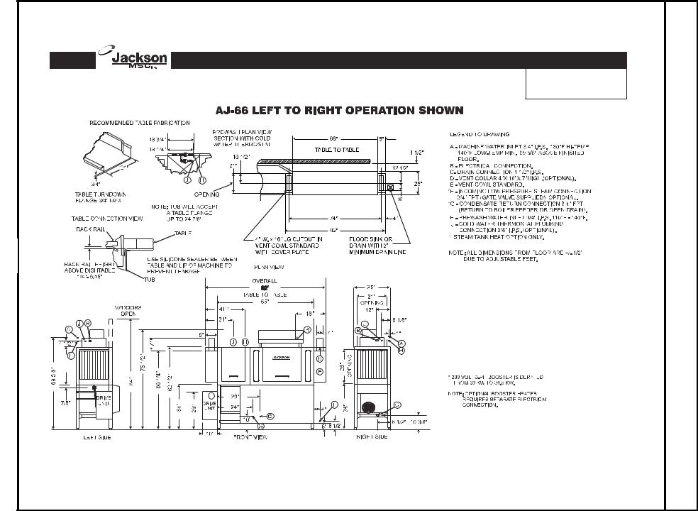
AJ-66 Vision Series |
|
Single-Tank Rack |
|
Conveyor Dishwashers |
6 |
DIRECTION) RIGHT TO (LEFT 66-AJ |
|
DIMENSIONS |

|
AJ-66 Vision Series |
|
Single-Tank Rack |
|
Conveyor Dishwashers |
7 |
DIRECTION) LEFT TO (RIGHT 66-AJ |
|
DIMENSIONS |
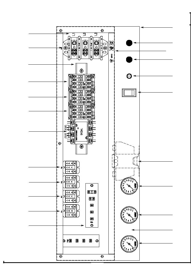
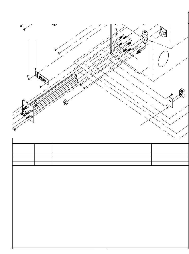
AJ-66 SINGLE PHASE CONTROL BOX ASSEMBLY |
1 |
2 |
6 |
3, 4, 5 |
4, 7, 10, 11, 12 |
8 |
4, 9, 10 |
15 |
14 |
16 |
14 |
14 |
10, 18 |
19, 20 |
21, 22 |
21, 22 |
24 |
21, 22 |
21, 23 |
25 |
13, 21 |
26 |
25 |
8 |
AJ-66 SINGLE PHASE CONTROL BOX ASSEMBLY (CONTINUED)
|
|
|
|
|
|
|
|
|
|
|
|
ITEM |
|
QTY |
DESCRIPTION |
MFG No. |
|
|
|
|
1 |
|
1 |
Electrical Box Weldment |
5700-041-88-50 |
|
|
|
|
2 |
|
1 |
Decal, L1-L2-L3 |
9905-101-12-66 |
|
|
|
|
3 |
|
1 |
Terminal Block |
5940-011-48-27 |
|
|
|
|
4 |
|
6 |
Lockwasher, #10 |
5311-273-02-00 |
|
|
|
|
5 |
|
2 |
Screw, 10-32 x 3/4" Long Phillips Trusshead |
5305-011-62-17 |
|
|
|
|
6 |
|
1 |
Light, Amber |
5945-111-44-44 |
|
|
|
|
7 |
|
1 |
Wire Lug, 2 AWG to 14 AWG |
5940-200-76-00 |
|
|
|
|
8 |
|
1 |
Light, Red |
5945-111-44-45 |
|
|
|
|
9 |
|
1 |
Din Rail |
5700-021-72-75 |
|
|
|
|
10 |
|
3 |
Screw, 10-32 x 1/2" Long Phillips Trusshead |
5305-011-39-36 |
|
|
|
|
11 |
|
1 |
Washer, Flat, 1/4" ID |
5311-174-01-00 |
|
|
|
|
12 |
|
1 |
Decal, Ground |
9905-011-86-86 |
|
|
|
|
13 |
|
1 |
Terminal Board |
5940-021-70-70 |
|
|
|
|
14 |
|
3 |
Motor Contactor |
5945-111-68-38 |
|
|
|
|
15 |
|
1 |
Circuit Breaker |
5925-011-68-34 |
|
|
|
|
16 |
|
1 |
Switch, ON/FILL & OFF/DRAIN |
5930-301-46-00 |
|
|
|
|
17 |
|
1 |
Heater Contactor |
5945-111-68-37 |
|
|
|
|
18 |
|
1 |
Transformer |
5950-011-68-35 |
|
|
|
|
19 |
|
4 |
Locknut, 10-24 with Nylon Insert |
5310-373-01-00 |
|
|
|
|
20 |
|
12 |
Screw, 6-32 x 3/8" Long Phillipshead |
5305-171-02-00 |
|
|
|
|
21 |
|
3 |
Control Relay |
5945-111-35-19 |
|
|
|
|
22 |
|
1 |
Relay |
5945-111-72-51 |
|
|
|
|
23 |
|
1 |
Thermometer, 48" Lead |
6685-111-68-48 |
|
|
|
|
24 |
|
2 |
Thermometer, 96" Lead |
6685-111-68-49 |
|
|
|
|
25 |
|
1 |
Decal, AJ-66 Gauge |
9905-021-72-30 |
|
|
|
|
26 |
|
1 |
Terminal Board |
5940-021-89-41 |
|
|
|
|
|
|
|
|
|
|
|
|
|
MISCELLANEOUS PARTS NOT SHOWN: |
|
|
|||
|
|
|
Grommet, 1/2” OD x 3/8” ID |
|
5325-011-46-73 |
|
||
|
|
|
Bushing, Heyco SB100 |
|
5975-210-09-00 |
|
||
|
|
|
Plug, Heyco 2700 G-875 |
|
5975-011-47-81 |
|
||
|
|
|
Control Box Cover |
|
|
5700-031-89-42 |
|
|
|
|
|
Control Box Cover Hinge Weldment |
5700-021-68-57 |
|
|||
|
|
|
Control Hinge Rod |
|
|
5700-011-68-58 |
|
|
|
|
|
Washer, Flat, S/S, 1/4” ID |
|
5311-174-01-00 |
|
||
|
|
|
Cotter Pin |
|
|
5315-011-68-56 |
|
|
|
|
|
MANUAL/DELIME Switch (located on rear of control box) |
5930-301-22-18 |
|
|||
|
|
|
MANUAL/DELIME Switch Decal (located on rear of control box) |
9905-011-74-61 |
|
|||
|
|
|
Copper Conductors Only Decal |
9905-011-47-35 |
|
|||
|
|
|
Control Box Leg |
|
|
5700-011-71-47 |
|
|
|
|
|
Bolt, 1/4”-20 x 2-1/2” Long Hex Head |
5306-011-83-52 |
|
|||
|
|
|
Locknut, 1/4”-20 with Nylon Insert |
5310-374-01-00 |
|
|||
|
|
|
Component Mounting Plate (located inside the control box) |
5700-031-67-03 |
|
|||
9
|
AJ-66 THREE PHASE CONTROL BOX ASSEMBLY |
|
1 |
2 |
|
|
6 |
3, 4, 5 |
4, 7, 10, 11, 12 |
|
|
|
8 |
4, 9, 10 |
|
|
15 |
14 |
16 |
|
17 |
14 |
|
|
18 |
14 |
19 |
20, 21 |
|
24, 25, 26 |
22, 23 |
|
|
26, 27 |
|
26, 27 |
|
|
29 |
26, 27 |
|
|
31 |
26, 28 |
|
|
30 |
13, 26 |
|
26,32 |
30 |
|
|
|
10 |

AJ-66 THREE PHASE CONTROL BOX ASSEMBLY (CONTINUED)
|
|
|
|
|
|
|
ITEM |
QTY |
DESCRIPTION |
MFG No. |
|
|
1 |
1 |
Electrical Box Weldment |
5700-041-88-50 |
|
|
2 |
1 |
Decal, L1-L2-L3 |
9905-101-12-66 |
|
|
3 |
1 |
Terminal Block |
5940-011-48-27 |
|
|
4 |
6 |
Lockwasher, #10 |
5311-273-02-00 |
|
|
5 |
2 |
Screw, 10-32 x 3/4" Long Phillips Trusshead |
5305-011-62-17 |
|
|
6 |
1 |
Light, Amber |
5945-111-44-44 |
|
|
7 |
1 |
Wire Lug, 2 AWG to 14 AWG |
5940-200-76-00 |
|
|
8 |
1 |
Light, Red |
5945-111-44-45 |
|
|
9 |
1 |
Din Rail |
5700-021-72-75 |
|
|
10 |
3 |
Screw, 10-32 x 1/2" Long Phillips Trusshead |
5305-011-39-36 |
|
|
11 |
1 |
Washer, Flat, 1/4" ID |
5311-174-01-00 |
|
|
12 |
1 |
Decal, Ground |
9905-011-86-86 |
|
|
13 |
1 |
Terminal Board |
5940-021-70-70 |
|
|
14 |
3 |
Motor Contactor |
5945-111-68-38 |
|
|
15 |
1 |
Circuit Breaker (200/208/220/230/380 (60 Hz) Volt Models Only) |
5925-011-68-34 |
|
|
16 |
1 |
See Page Entitled "Motor Overloads" |
N/A |
|
|
17 |
1 |
Switch, ON/FILL & OFF/DRAIN |
5930-301-46-00 |
|
|
18 |
1 |
See Page Entitled "Motor Overloads" |
N/A |
|
|
19 |
1 |
See Page Entitled "Motor Overloads" |
N/A |
|
|
20 |
1 |
Heater Contactor |
5945-002-24-70 |
|
|
21 |
2 |
Screw, 10-32 x 3/8" Long Phillips Trusshead |
5305-173-12-00 |
|
|
22 |
1 |
Transformer (200 Volt Models Only) |
5950-002-41-47 |
|
|
22 |
1 |
Transformer (208/220/230/460 Volt Models Only) |
5950-011-68-35 |
|
|
22 |
1 |
Transformer (380/415 Volt Models Only) |
5950-011-75-59 |
|
|
22 |
1 |
Transformer (600 Volt Models Only) |
5950-002-23-77 |
|
|
23 |
4 |
Locknut, 10-24 with Nylon Insert |
5310-373-01-00 |
|
|
24 |
1 |
Fuse Holder (380 (60 Hz)/460/600 Volt Models Only) |
5920-011-72-89 |
|
|
25 |
1 |
Fuse (380 (60 Hz)/460/600 Volt Models Only) |
5920-011-72-88 |
|
|
26 |
12 |
Screw, 6-32 x 3/8" Long Phillipshead |
5305-171-02-00 |
|
|
27 |
3 |
Control Relay |
5945-111-35-19 |
|
|
28 |
1 |
Relay |
5945-111-72-51 |
|
|
29 |
1 |
Thermometer, 48" Lead |
6685-111-68-48 |
|
|
30 |
2 |
Thermometer, 96" Lead |
6685-111-68-49 |
|
|
31 |
1 |
Decal, AJ-66 Gauge |
9905-021-72-30 |
|
|
32 |
1 |
Terminal Board |
5940-021-89-41 |
|
MISCELLANEOUS PARTS NOT SHOWN: |
|
Grommet, 1/2” OD x 3/8” ID |
5325-011-46-73 |
Bushing, Heyco SB100 |
5975-210-09-00 |
Plug, Heyco 2700 G-875 |
5975-011-47-81 |
Control Box Cover |
5700-031-89-42 |
Control Box Cover Hinge Weldment |
5700-021-68-57 |
Control Hinge Rod |
5700-011-68-58 |
Washer, Flat, S/S, 1/4” ID |
5311-174-01-00 |
Cotter Pin |
5315-011-68-56 |
MANUAL/DELIME Switch (located on rear of control box) |
5930-301-22-18 |
MANUAL/DELIME Switch Decal (located on rear of control box) |
9905-011-74-61 |
Copper Conductors Only Decal |
9905-011-47-35 |
Control Box Leg |
5700-011-71-47 |
Bolt, 1/4”-20 x 2-1/2” Long Hex Head |
5306-011-83-52 |
Locknut, 1/4”-20 with Nylon Insert |
5310-374-01-00 |
Component Mounting Plate (located inside the control box) |
5700-031-67-03 |
11

MOTOR OVERLOADS
Model |
Volts |
Hz |
Phase |
Drive Motor |
Prewash Motor |
Wash Motor |
AJ-66CE/CEL |
208 |
50 |
3 |
5945-011-84-59 |
5945-002-24-70 |
5945-111-68-40 |
AJ-66CE/CEL |
220 |
50 |
3 |
5945-011-84-59 |
5945-002-24-70 |
5945-111-68-40 |
AJ-66CE/CEL |
230 |
50 |
3 |
5945-011-84-59 |
5945-002-24-70 |
5945-111-68-40 |
AJ-66CE/CEL |
380 |
50 |
3 |
5945-111-69-12 |
5945-002-24-70 |
5945-111-81-33 |
AJ-66CE/CEL |
415 |
50 |
3 |
5945-111-69-12 |
5945-002-24-70 |
5945-111-81-33 |
AJ-66CE/CEL |
440 |
50 |
3 |
5945-111-69-12 |
5945-002-24-70 |
5945-111-81-33 |
AJ-66CE/CEL |
208 |
60 |
1 |
N/A |
N/A |
N/A |
AJ-66CE/CEL |
230 |
60 |
1 |
N/A |
N/A |
N/A |
AJ-66CE/CEL |
200 |
60 |
3 |
5945-111-68-39 |
5945-111-68-41 |
5945-111-68-40 |
AJ-66CE/CEL |
208 |
60 |
3 |
5945-111-68-39 |
5945-111-68-41 |
5945-111-68-40 |
AJ-66CE/CEL |
230 |
60 |
3 |
5945-111-68-39 |
5945-111-68-41 |
5945-111-68-40 |
AJ-66CE/CEL |
380 |
60 |
3 |
5945-111-69-12 |
5945-002-24-70 |
5945-111-81-33 |
AJ-66CE/CEL |
460 |
60 |
3 |
5945-111-68-39 |
5945-111-68-41 |
5945-111-68-40 |
AJ-66CE/CEL |
600 |
60 |
3 |
5945-111-69-12 |
5945-002-24-70 |
5945-111-68-41 |
12
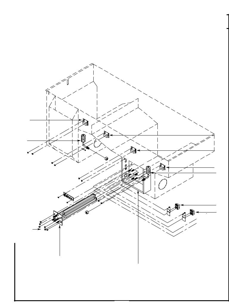
HEATER BOX ASSEMBLY |
AJ-66 TUB |
13, 15 |
12, 14 |
9 |
12, 14 |
12, 14 |
8 |
7 |
6 |
3, 4, 5 |
1, 2 |
10, 11
13

HEATER BOX ASSEMBLY (CONTINUED)
|
|
ITEM |
QTY |
DESCRIPTION |
MFG No. |
|
1 |
1 |
See Page Entilted "Wash Heaters" |
N/A |
|
|
2 |
1 |
Heater Gasket |
5330-200-02-70 |
|
|
3 |
6 |
Washer, Flat, 5/16" |
5311-175-01-00 |
|
|
4 |
6 |
Lockwasher, 5/16" |
5311-275-01-00 |
|
|
5 |
6 |
Nut, 5/16"-18 |
5310-275-01-00 |
|
|
6 |
1 |
Thermostat, Wash Regulating |
5930-121-67-72 |
|
|
7 |
1 |
Thermostat, High Limit Control |
5930-121-71-36 |
|
|
8 |
1 |
Float Switch (Wash Tank) |
6680-121-70-71 |
|
|
9 |
1 |
Float Switch (Prewash Tank) |
6680-121-70-16 |
|
|
10 |
1 |
Heater Box Weldment (AJ-44 Only) |
5700-031-66-81 |
|
|
10 |
1 |
Heater Box Weldment (AJ-66/AJ-80 Only) |
5700-031-71-66 |
|
|
11 |
6 |
Locknut, 1/4"-20 with Nylon Insert |
5310-374-01-00 |
|
|
12 |
3 |
Reed Switch (All Models) |
5930-111-68-44 |
|
|
13 |
1 |
Reed Switch (AJ-66 and AJ-80 Models Only) |
5930-111-68-44 |
|
|
14 |
3 |
Reed Switch Bracket (All Models) |
5700-021-71-18 |
|
|
15 |
1 |
Reed Switch Bracket (AJ-66 and AJ-80 Models Only) |
5700-021-71-18 |
|
The wash tank heater system is electrically connected in the circuit so that they are dependent upon the dishwasher being properly filled with and maintaining a safe water level, two thermostats (mounted in the heater box behind the dress panel), float switch (mounted in the wash tank), and the heater relay (mounted in control box) with the heater being activated by the thermostats.
Once the dishwasher has been filled to the correct level, the heater should operate automatically. Should the tank heat be too high, too low or no indication of temperatures at all, the following checkout should be made.
Note: The following checkout should be made by either a qualified service person or electrician.
A.- Checkout of the heater system
1.- If the temperature is too high, adjust thermostat using instructions on the page entitled “Thermostats”. 2.- If temperature is too low, adjust thermostat as above, then:
a.- Turn off power to machine by placing customer’s circuit breaker in the “OFF” position. Turn off machine circuit breaker located on right side of control box.
b.- Remove cover from control box on top of dishwasher.
c.- Make sure water temperature is below 140 degrees F.(preferably about 130 degrees F.).
d.- Turn on both circuit breakers. Observe heater relay (R1) while the power switch is turned “ON” and “OFF”. If relay contacts move in and out, the heater relay is operating correctly: if not proceed to ”C”.
B.- If heater relay (R1) closes:
1.- Check power supply at incoming terminal board L1, L2 & L3. It should be the same voltage as indicated on the machine data plate.
2.- Check power at connections on heater relay (R1). The voltage should agree with the voltage on the machine data plate. If not, check wires for breaks or bad connections.
3.- Check power at terminals of heater which should agree with the data plate. If not check wires for breaks or bad con -nections.
4.- Temperatures should rise as explained in “C-1”, and amperage may be checked according to those instructions. Replace any defective elements.
C.- If heater relay (R1) does not close.
1.- There is an insulated movable insulated movable bar on relay across the top. With an insulated probe, depress this bar and observe the thermometer: the temperature should rise noticeably in a minute or two. If it moves slowly, it would indicate that the element is faulty. If it moves constantly higher at a good rate, elements should be good.
Note: A check with an amp probe at heater relay (R1) terminals should be made to verify the amp draw on each leg. This should be appropriate for the voltage and phase indicated on the data plate.
14
|
|
HEATER BOX ASSEMBLY (CONTINUED) |
|
2 |
1 |
|
|
|
|
3 |
|
ITEM |
QTY |
DESCRIPTION |
MFG No. |
1 |
1 |
Terminal Board |
5940-021-70-70 |
2 |
2 |
Locknut, 6-32 with Nylon Insert |
5310-373-03-00 |
3 |
1 |
Thermostat Bracket |
5700-011-73-72 |
HEATER PROTECTION & AUTOMATIC FILL
This control is activated when the power switch is turned “ON”. The primary function is to automatically energize the wash tank heat circuit. It will also cutoff the wash tank heat circuit should the water be accidently drained from the machine with the power switch still “ON”. The power switch should always be turned-off before draining the unit.
This water level control consists of two (2) floats that operate when the power switch is turned on and works in conjunction with the thermostats and heater relays.
When the power switch is turned “ON” water starts to enter the dishmachine. When it reaches the proper level the normally open contacts in the water level float switch close activating the heating circuit for tank heat.
If the water level below the correct level while power is still on, the float switch will sense the lack of water and de-activate the heater.
15
HEATER BOX COVER/THERMOSTATS
AJ-66 Heater Box Cover 5700-031-71-70
Secured with Screw, 10-32 x 3/8” Long Phillips Trusshead 5305-173-12-00
THERMOSTATS:
This unit has a probe-direct sensing type thermostat with fixed set point and adjustable range for both wash and booster tank heat regulating. The same type thermostat is used as the high limit sensor for the wash tank heater. It operates a precision single double throw switch through a lever for close tolerance narrow differential switching capability. There are two (2) thermostats on the dishwasher. One monitors the wash tank temperature, the second monitors the rinse water temperature. Although all are identical in appearance there are different replacement part numbers depending on the function of the thermostat.
To order decals that go with the thermostats: |
|
Decal, Thermostat Regulating |
9905-011-84-31 |
Decal, High Limit |
9905-011-84-32 |
16
 Loading...