

Invacare XLT Dynamic, XLT Active, XLT Swing, XLT Max User Manual

Manual
English
Invacare
®

©Invacare© Rea™ AB
Every effort has been made to ensure that the contents of
this publication are updated at the time of printing. As part of
the ongoing improvement of the products, Invacare Rea AB
reserves the right to modify existing models at any time.
Any use of this publication, or parts thereof, as well as any
reproduction of images, must have the written consent of
Invacare Rea AB
2 INVACARE® XLT
9
Contents
Product description 4
XLT models 5
Intended use 7
Upholstery and frame colours 8
Equipment and accessories 8
Technical data 9
Delivery check 10
Assembly 10
Adjustments 12
Footbow 12
Fixed legrests 13
Angle adjustable legrests 13
Calf pads/ footplates 14
Footrests one-piece 14
Seat 15
Backrest 16
Armrests/mudguard 19
Brakes 20
Rear wheel attachment 21
Camber 21
Rear wheel attachment xlt max 22
Castor wheels 23
Seat height tables 24
Accessories 33
Anti-tip devices 33
Trunk support 35
One-arm drive 36
Anti-tip device for one-arm drive 36
Assistant manoeuvred 37
Drumbrakes 37
Amputee legrest 38
External push handles 38
Foldable push handles 38
Head and neckrest 39
Pelvic belt 40
Transport as luggage 41
Transporting wheelchairs in vehicles 42
Restraint methods 44
Safety instructions/
Propelling techniques 45
Guarantee 47
Maintenance instructions 47
10
5
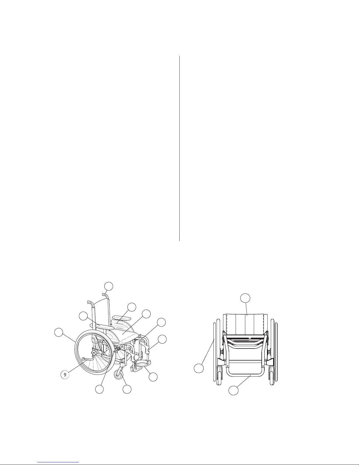
1. Frame (chassis)
2. Backrest
3. Push handles
4. Seat
5. Rear wheel
Parts of the wheelchair
3
11
4
1
12
6
13
7
8
6. Hand rims
7. Brakes
8. Castors
9. Anti tip device
10. Armrests
2
14
11. Jaw
12. Legrests
13. Footrest
14. Footbow
®
INVACARE
XLT
3

Product description
®
Invacare
Invacare® XLT is a wheelchair with many adjustment options and
accessories. To ensure that you benefit as much as possible from your
Invacare® XLT, and in order to do its options justice, the chair must be
tested and adjusted by competent personnel. We hope that you have also
received instructions for using your Invacare® XLT in everyday life.
The Invacare® XLT frame, footbow and backrest are manufactured
from high quality titanium. For the Swing version the legrest hangers
are made from aluminium. The cover for the seat cushion is made of
Jemima and the backrest cover is made of nylon.
This manual includes a description of the parts of the chair, simple
adjustment options, how to use the Invacare® XLT safely and how
to transport it. The manual must be read thoroughly before the chair
is used. Also included in this manual is a description of how the most
common accessories are fitted and also some slightly more advanced
settings.
As the Invacare® XLT has many different components and accessories,
the appearance of the accessories you have for your chair may differ
from those shown.
XLT
4 INVACARE® XLT

XLT Models
1.
2.
XLT is available in four models.
1. XLT Active (75° knee angle)
The XLT Active front is designed to hold your
feet and lower parts of your leg steady. The
footbow is standard.
Seat angles 0-14° can be obtained, depending on
the size of castors and rear wheels and the row
of mounting holes used for the castors and rear
wheels.
2. XLT Dynamic (90° knee angle)
The XLT Dynamic is designed to hold your feet
steady. The total length of the wheelchair is very
compact. The footbow is standard.
Seat angles 0-14° can be obtained, depending on
the size of castors and rear wheels and the row
of mounting holes used for the castors and rear
wheels.
4.
3.
3. XLT Swing (80°, 90° and angle adjustable
legrests)
The XLT Swing is designed with a front offering
more space for the feet and lower parts of the
legs. The standard delivery includes collapsible
footrests.
Seat angles 0-14° can be obtained, depending on
the size of castors and rear wheels and the row
of mounting holes used for the castors and rear
wheels.
4. XLT Max (75°)
The XLT Max is designed for larger users and has
a user weight capacity of 180 kg.
Seat angles 0-14° can be obtained, depending on
the size of castors and rear wheels and the row
of mounting holes used for the castors and rear
wheels.
®
INVACARE
XLT
5
NB!
This symbol means warning.
On this page a number of points affecting your personal safety are
shown. Please read it carefully!
Invacare
sonnel who we authorise. We reserve the right to make any changes
to equipment and specifications without prior notice.
Failure to comply with instructions given may result in personal injury
and/or product damage.
• Check each of the following before using the wheelchair:
- that all parts are attached securely to the frame
- that all wheels and knobs are properly tightened
- that all brakes and anti-tip devices function correctly
• Never lift the wheelchair by the detachable armrests, footrests,
• Always apply the brake before getting into or out of the chair.
• Never stand on the footplates when getting into or out of the chair,
• Changing the seat angle can give an increased risk of tipping over.
• The hand rims may become hot due to friction, and this may cause
• Use extensively the anti-tip device
• Remember that the effectiveness of the carer-operated brake
• Be careful to ensure that the drive wheels are securely attached.
• Drive wheels are not to be detached while the user is sitting in the
• The more the backrest cover’s Velcro straps are slackened the
• Surfaces of the wheelchair like frame parts or upholstery can with
®
is only responsible for product changes carried out by per-
backrest bar or by the adjustable push handles.
because of the risk of tipping.
injury to your hands.
is reduced in wet and slippery conditions, as well as when on a
slope.
chair.
greater the risk of tipping the wheelchair becomes.
long time exposure to sun reach temperatures over 41 °C.
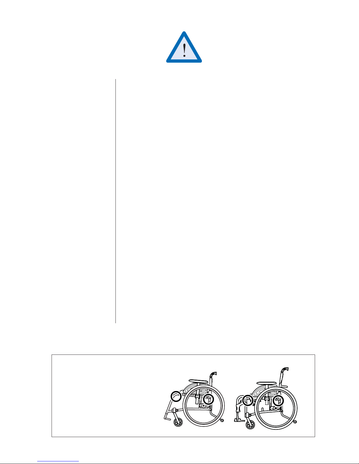
Always lift the wheelchair by grabbing the
frame at the points shown in the picture.
Never lift the wheelchair by the removable
armrests, the footrests or the backrest bar.
Ensure that the backrest and push handles
are securely in place. Also read the chapter
Safety instructions/Propelling techniques.
6 INVACARE® XLT
LIFTING THE WHEELCHAIR

Intended use
• Invacare® XLT is a manual wheelchair aimed for those who use the wheelchair for a longer period of time, i.e. several hours in a row.
• Invacare® XLT is designed for the user who can manoeuvre the wheelchair
him/herself, as well as for the user who requires assistance.
• Invacare® XLT is versatile and has accessories that makes it possible to
adjust the sitting posture so it stays comfortable for several hours.
• Invacare® XLT has many adjustment possibilities. With the right adjustments, carried out by a professional, the wheelchair can be set up specifically
for a user and according to the requirements of a possible assistant.
• Invacare® XLT can be used both indoors and outdoors on level ground
and paved areas. We recommend the larger wheels when the wheelchair
is used on uneven ground.
• Note that there is an increased risk that the Invacare® XLT could tip
backwards, when being wheeled uphill, especially when the incline is more
than 8°. Or if the rear wheels are mounted in their formost position on
the rear wheel attachment. The effect of mounting the rear wheels in their
foremost position is that the chair will be easier to manoeuvre. However,
there is the increased risk of tipping backwards. Therefore the use of anti
tip devices to achieve better stability is strongly recommended.
• Invacare® XLT is designed to have a seat cushion on the seat. The seat
cushion improves the user's body posture and makes it possible to sit
comfortably for longer periods of time.
Invacare® XLT with a backrest, adjusted to a height of minimum •
40 cm, a neckrest and a pelvic belt can be used as a seat in a vehicle. For
other configurations the user must transfer to the normal seat in a car
or bus.
Daily performance check
Check that the following parts are securely fitted on the wheelchair
and operational:
• Wheels
• Brakes
• Backrest
• Anti-tip device, if fitted
• Push handles, if fitted
• Footrests or footbow
• Pelvic belt, if fitted
• Neck-/headrest, if fitted
®
INVACARE
XLT
7

UPHOLSTERY AND FRAME COLOURS
Backrest cover Black Nylon TR33
Seat cushion cover Black Jemima TR18 (standard)
Frame colours Black, Grey, Blue, Red, Blasted titanium and Orange
EQUIPMENT AND ACCESSORIES
Invacare® XLT has a wide range of accessories and options. Some of the accessories may not be available
in all countries and all accessories are not available for all models.
Backrest
Tension adjustable
Angle adjustable, fixed or height adjustable
Narrow back
Seat
Tension and depth adjustable seat
Seat cushions
Standard 5 cm, Flotech/Contour
Legrests
Footbow rigid**
Footbow rigid with footplate**
Footrest one piece, flipup, angle adjustable
Footrest, high mounted**
80° & 90° fixed legrest*
Angle adjustable legrest*
Fixed footplate*
Angle and depth adjustable footplate*
Armrests
Flip-up armrest with long or short pad
Height adjustable armrest "Rio", with long or short
pad
Hemi armrest
Comfort armrest***
Others
Several types of handrims
Spoke guard
Headrest
Neckrest
Headrest with cheek support
Anti-tip device
Trunk Support
Reflectors Kit
Table Tray
Pump
Cane holder
Tool kit
Various push handles
Pelvic belt
Mudguard
Sideguard
Step tube
Brake lever extension
Mounting brackets for E-Motion and E-Fix
* for XLT Swing only
** for XLT Active, Dynamic and Max
*** for XLT Max only
Castors
75 - 125 mm Dynamic
75 - 180 mm Swing, Active
140 - 180 Max
Rear wheels
22", 24", 25", 26" pneumatic or puncture-proof
24", one-arm drive
Brake
User-brake (3 types)
Carer-operated drumbrake
One-arm brake
8 INVACARE® XLT
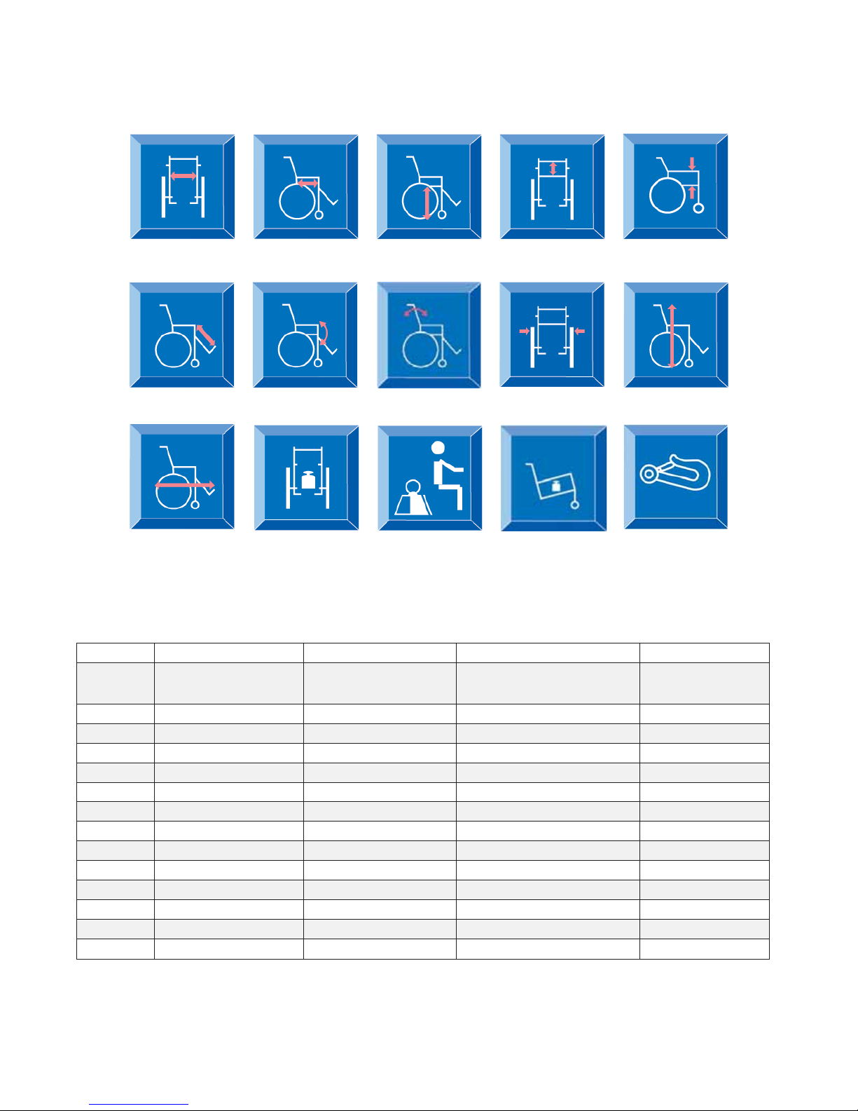
Technical data
SW= Seat width SD= Seat depth
SH=Seat height
BH= Backrest
height
LL= Legrest
lenght
L= Lenght
SA= Seat angle
M=Weight
BA= Bacrest
angle
ML= Max user
weight
* Fixed/Angle adjustable backrest
**Our wheelchairs are crash tested according to the ISO norm 7176-19 (Wheeled mobility devices for use as seats in motor vehicles) See the
chapter on Transport for more details. Wheelchair users should however transfer to the vehicle seat and use the vehicle installed restraint
system whenever it is feasible.
W= Width
TW= Transport
weight
AH= Armrest
height
H= Height
Crash test**
Active Dynamic Swing Max
SW (cm)
SD (cm)
SH (cm)*
35,5/38/40,5/43/45,5/48 35,5/38/40,5/43/45,5/48 33/35,5/38/40,5/43/45,5/48/50,5
36-40/41-45/46-50 36-40/41-45/46-50 36-40/41-45/46-50
40-52 40-50
39-52 44-52 cm
50,5 55,5, 60,5 cm
50, 55, 60 cm
BH (cm)* 20-35 / 30-49 20-35 / 30-49 20-35 / 30-49 40-49 cm
AH (cm) 21-31 21-31 21-31
LL (cm)* 38-50,5 35,5-48,5 28-51 38-48 cm
SA (°) 0°-14° 0°-14° 0°-14° 0°-14°
BA (°)
±10° ±10° ±10° ±10°
W (cm)** Seat width + 20 cm Seat width + 20 cm Seat width + 20 cm Seat width + 21 cm
H (cm) 61-105 61-105 61-105 79-110 cm
L (cm) 83-103 73-88 82-123 93-108 cm
M (kg) 9,8 9,8 11,3 21 kg
ML (kg) 135 135 135 180kg
TW (kg)*** 6 6 6 13,3 kg
* without seat cushion
** with 0° camber
*** without rearwheels and accessories
®
INVACARE
XLT
9
Delivery check
Check that all components comply with the delivery note. Any damage incurred during transport should be
reported immediately to the delivery company. Retain all packaging until the transport company has inspected
the consignment and an agreement has been reached.
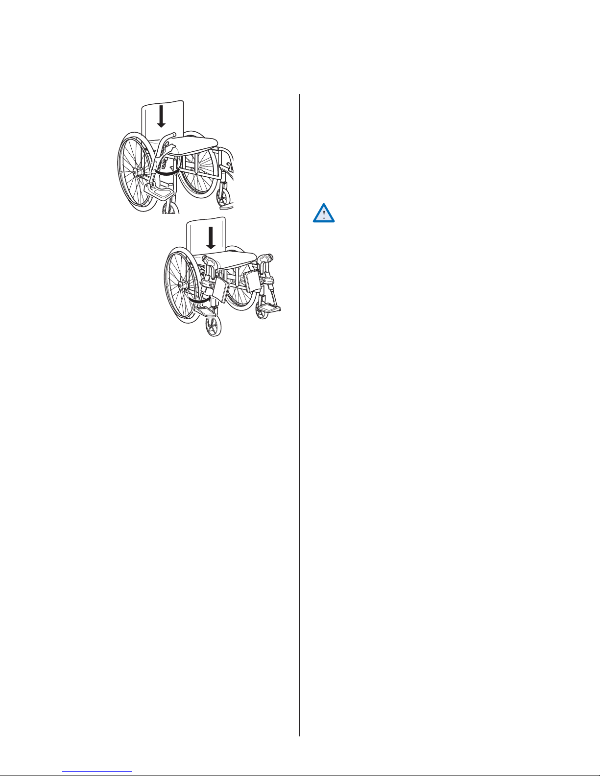
Assembly
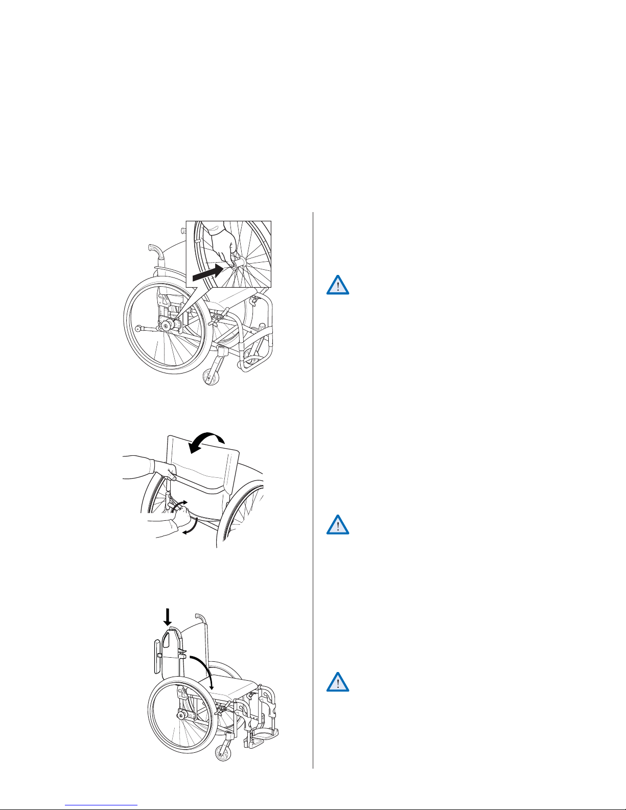
1.
2.
1. Attach the rear wheels by pressing the button in
the centre of the hub whilst simultaneously sliding
the axle onto the rear wheel position attachment
of the positioning plate.
It is very important that you check that the
locking pin has actually locked the wheel into
position when the centre button has been
released. Take hold of the wheels and try to
detach them. This should NOT be possible.
2. Unfold the backrest by grabbing the wire at the
lower back of the backrest and twisting it to
release the backrest locking pins. Pull the backrest
backwards/uppwards until it is fixed into place.
Check that it is fixed properly. The XLT Max does
not have a locking function. Just pull the backrest
upwards and check that it is fixed in place.
3.
10 INVACARE® XLT
Be careful not to trap your fingers between the
frame and the backrest attachments.
3. Armrests
Insert the armrests by fitting them into the attach-
ments on the backrest frame and then swinging
them down into position.
When using detachable armrests, just push them down
into place in their receiver.
Do not place your fingers on the seat frame.
4.
4. Legrests (XLT Swing)
Attach the legrests by pushing the tube at the
upper part of the legrests down into the tubes
on the wheelchair. You must angle the legrests
outwards when inserting them.
Lock the legrests by turning them inwards. The
legrests are automatically locked so there is no
risk of them coming off the wheelchair.
Be careful not to trap your fingers between
frame and legrest.
®
INVACARE
XLT
11
Adjustments
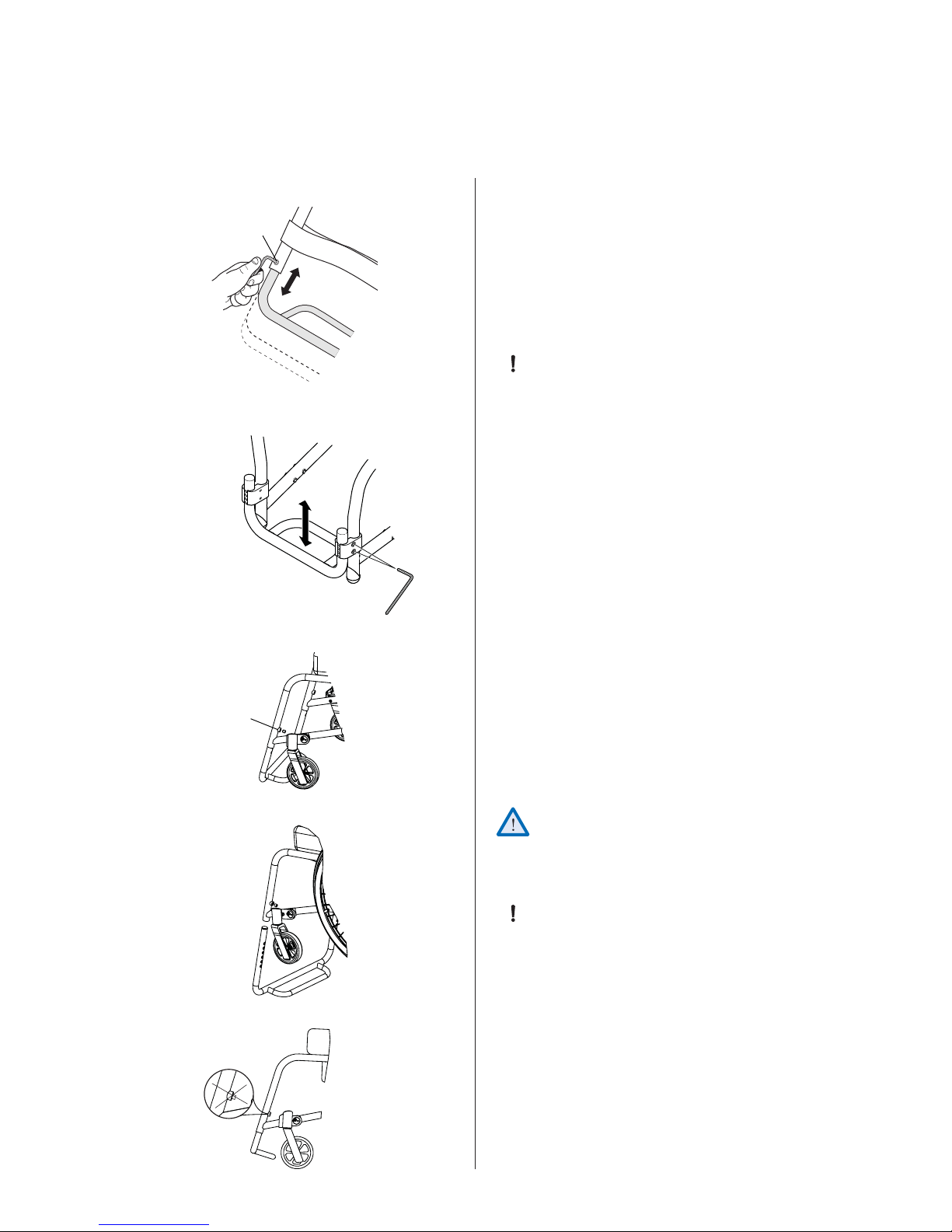
FOOTBOW
It is important to adjust the footbow, footrests, legrests, footplates and calf pads to obtain a good seating position
A
Height adjustment, footbow
Loosen the screws (A) using an Allen key, remove
them, and adjust the footbow to the correct height.
Retighten the screws and adjust the calf-strap.
Important
Tools: 4 mm Allen Key
10 mm fixed spanner
The distance between the lowest part of the
footrest and the floor or ground must be at
least 40 mm.
High mounted footbow
Loosen the screws (B) using an Allen key and adjust
the clamp and footbow to a suitable height. Retighten
the screws and adjust the calf-strap.
Tools: 5 mm Allen Key
C
B
Footbow XLT Max
Loosen the screws (C) using an Allen key and adjust
the footbow to a suitable height using one of six
holes on the footbow tube. Retighten the screws and
adjust the calf-strap. Make sure that the screws do not
protrude out of the casing.
Warning!
Risk of injury
The footbow can fall out if the screws are not
tightened properly. Make sure that both screws
are positioned in the holes on the tube.
Important
The distance between the lowest part of the
footrest and the floor or ground must be at
least 40 mm.
12 INVACARE® XLT
Tools: 5 mm Allen Key
Tools: 5 mm Allen Key
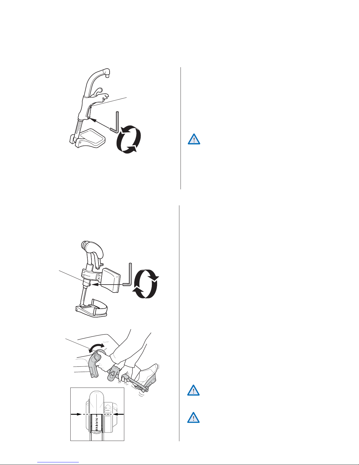
FIXED LEGRESTS
Height adjustment
Adjust the height of the footrests by loosening the
screw (A) with an Allen key. When adjusting the height
C
A
a clicking sound will occur. One ”click” is one step in
height. Pull the legrest until you have obtained the
correct height and the screw is caught by one of the
recesses on the legrest tube. Then retighten screw.
NOTE! Do not adjust the upper screw (C).
The distance between the lowest part of the
footrest and the floor or ground must be at
least 40 mm.
ANGLE ADJUSTABLE LEGRESTS
2.
A
1.
Angle adjustable legrests support the legs and reduce
pressure. The legrests can be used for bandaged legs,
but not for legs in plaster casts. The legrests must
always be fitted with calf pads, footplates and heel
straps.
It is important to adjust the height and angle of the
legrests to obtain a good seating position.
1. Height adjustment
Loosen screw (A) with an Allen key. Adjust the
Tools: 5 mm Allen Key
B
C
legrest into a suitable height and the screw is
caught by one of the recesses on the legrest tube.
Then retighten the screw.
2. Angle adjustment
Pull the lever (B) with one hand while support-
ing the legrest with your other hand. When a
suitable angle is obtained, let go of the lever and
the legrest will look into one of seven preset
positions (C).
Do not place anything heavy, or let children
sit on the legrest. It may cause damage to the
mechanism.
®
INVACARE
XLT
The distance between the lowest part of
the footrest and the ground must be at least
40 mm.
13
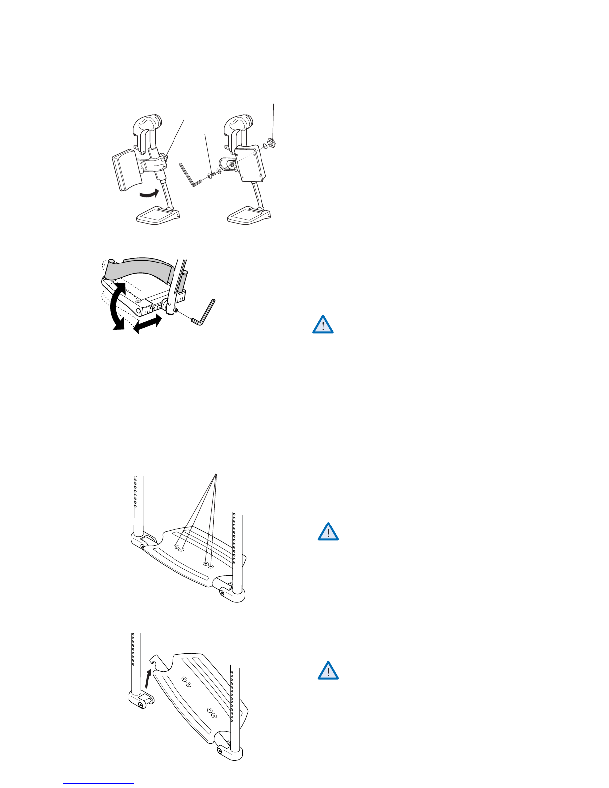
CALF PADS/ FOOTPLATES
Tools: 5 mm Allen Key
Tools: 5 mm Allen Key
C
D
B
Calf pads
The calf pads can be fitted in two different depth
positions. Swing the pad forwards. Unscrew screw
(B) using an Allen key. Remove the large nut (C) on
the reverse side and place it in the other attachment
hole. Move the calf pad to the new position and secure
it into place with the screw.
The height of the calf pads can easily be adjusted using
the handwheel (D).
Depth- and angle adjustable footplates
Adjust the angle and the depth by loosening the
screw (A) at the footplate attachment with a
5mm Allen key. Adjust the footplate to the correct
position and retighten the screw.
Do not place anything on the footplate when
A
the screws have been loosened.
1.
Tools: 4 mm Allen Key
10 mm fixed spanner
2.
FOOTRESTS ONE-PIECE
A
1. Footrest, one piece
Adjust the angle by loosening the four screws (A)
2. The footrest can be flipped up. Lift the right side
on the footplate attachment with a 4 mm Allen
key. Adjust the footplate to the correct position
and retighten the screws.
Do not place anything on the footplate when
the screws have been loosened.
of the footrest upwards.
Be careful not to trap your fingers between
the footrest and the receiver when you fold
down the footrest.
14 INVACARE® XLT

1.
Tools: 5 mm Allen Key
A
1. Footrest, one piece (XLT Swing)
Adjust the angle and the depth by loosening the
two screws (A) on the footplate attachment with
a 5 mm Allen key. Adjust the footplate to the correct position and retighten the screws.
Do not place anything on the footplate when
the screws have been loosened.
1.
2.
2. The footrest can be flipped up. Lift the left side of
the footrest upwards.
Be careful not to trap your fingers between
the footrest and the receiver when you fold
down the footrest.
SEAT
1. Adjusting the seat depth
Lift up the front part, slide into required depth.
2.
®
INVACARE
XLT
2. Adjusting the shape
(tension adjustable seat)
Use the straps underneath the seat to adjust the
shape of the seat. Always have a cushion on the
seat when testing its adjusted shape.
15
 Loading...