

Invacare Typhoon Service Manual
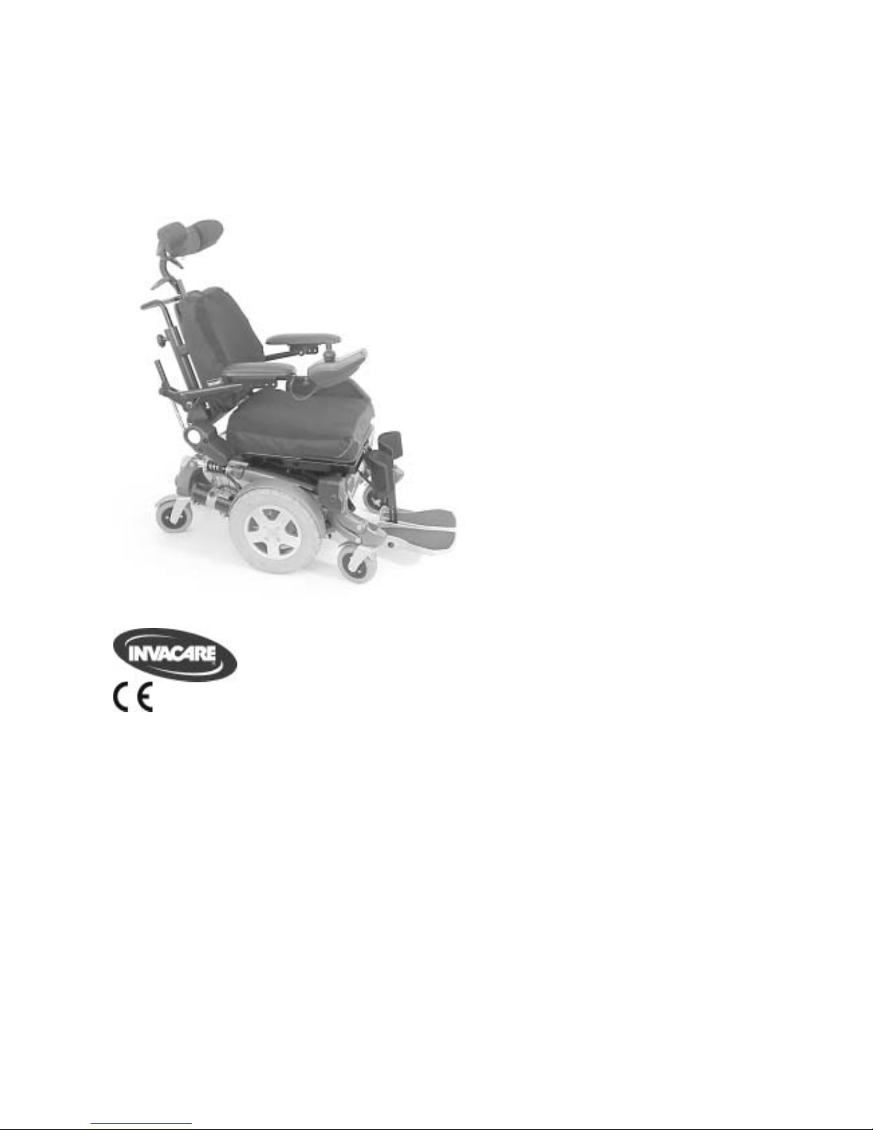
Invacare® Typhoon
SERVICE MANUAL
This document contains information on:
Troubleshooting
Maintenance
Repair
Version: 26.11.09
2
Mobitec Mobilitätshilfen GmbH
Herzog Odilostrasse 101
A-5310 Mondsee
Austria
+43 6232 55 35 0
Fax: +43 6232 55 35 4
@: office@mobitec-austria.com
@: austria@invacare.com
WWW: www.mobitec-austria.com
Invacare® n.v.
Autobaan 22
B-8210 Loppem (Brugge)
Belgium
+32 (0)50 83 10 10
Fax: +32 (0)50 83 10 11
@: belgium@invacare.com
WWW: www.invacare.be
Mobitec Rehab AG
Benkenstraße 260
CH-4108 Witterswil
Switzerland
+41 (0)61 48 77 08 0
Fax: +41 (0)61 48 77 08 1
@: office@mobitec-rehab.ch
@: switzerland@invacare.com
WWW: www.mobitec-rehab.ch
Invacare Aquatec
Alemannenstraße 10
88316 Isny
Deutschland
+49 (0)75 62 7 00 0
Fax +49 (0)75 62 7 00 66
@: info@invacare-aquatec.com
WWW: www.invacare-aquatec.de
Invacare® A/S
Sdr. Ringvej 37
DK-2605 Brøndby
Danmark
(Kundeservice): +45 (0)36 90 00 00
Fax (Kundeservice): +45 (0)36 90 00 01
@: denmark@invacare.com
WWW: www.invacare.dk
Invacare® SA
c/ Areny, s/n
Polígon Industrial de Celrà
E-17460 Celrà (Girona)
ESPAÑA
: +34 (0)972 49 32 00
Fax: +34 (0)972 49 32 20
@: contactsp@invacare.com
WWW: www.invacare.es
Invacare® Poirier SAS
Route de St Roch
F-37230 Fondettes
France
: +33 (0)247 62 64 66
Fax : +33 (0)247 42 12 24
@: contactfr@invacare.com
WWW: www.invacare.fr
Invacare® Ltd
Pencoed Technology Park
Pencoed
Bridgend CF35 5HZ
United Kingdom
(Customer Service): +44 (0)1656 776 200
Fax (Customer Service): +44 (0)1656 776 201
@: uk@invacare.com
@: eire@invacare.com
WWW: www.invacare.co.uk
Invacare Mecc San s.r.l.
Via Dei Pini, 62
I - 36016 Thiene (VI)
ITALIA
+39 0445 38 00 59
Fax: +39 0445 38 00 34
@: italia@invacare.com
WWW: www.invacare.it
Invacare Ireland Ltd.
Unit 5 Seatown Business Campus
Seatown Rd, Swords
County Dublin
Ireland
+353 18 10 70 84
Fax: +353 18 10 70 85
@: eire@invacare.com
WWW: www.invacare.ie
Invacare® AS
Grensesvingen 9
Postboks 6230
Etterstad
N-0603 Oslo
Norge
(Kundeservice): +47 (0)22 57 95 00
Fax (Kundeservice): +47 (0)22 57 95 01
@: norway@invacare.com
WWW: www.invacare.no
Invacare® B.V.
Celsiusstraat 46
NL-6716 BZ Ede
Nederland
: +31 (0)318 69 57 57
Fax: +31 (0)318 69 57 58
@: nederland@invacare.com
WWW: www.invacare.nl

3
Invacare Portugal, Lda
Rua Estrada Velha, 949
P-4465-784 Leça do Balio
Portugal
: +351 225 1059 46
: +351 225 1059 47
Fax: +351 225 1057 39
@: portugal@invacare.com
WWW: www.invacare.pt
Återförsäljare:
Invacare® AB
Fagerstagatan 9
S-163 91 Spånga
Sverige
Tillverkare:
Invacare® Deutschland GmbH
Kleiststraße 49
D-32457 Porta Westfalica
Deutschland
(Kundtjänst): +46 (0)8 761 70 90
Fax (Kundtjänst): +46 (0)8 761 81 08
@: sweden@invacare.com
@: finland@invacare.com
WWW: www.invacare.se
MÖLNDAL
+46 (0)31 86 36 00
Fax: +46 (0)31 86 36 06
@: ginvacare@invacare.com
LANDSKRONA
+46 (0)418 285 40
Fax: +46 (0)418 180 89
@: linvacare@invacare.com
OSKARSHAMN
+46 (0)491 101 40
Fax: +46 (0)491 101 80
@: oinvacare@invacare.com

4
Table of Contents
Chapter Page
1 INTRODUCTION 6
1.1 General information 6
1.2 Notes on transport 6
1.3 Important symbols in this manual 6
2 SAFETY AND ASSEMBLY INSTRUCTIONS 8
2.1 Before any inspection or repair work 8
2.2 General safety information and notes on assembly / disassembly 8
3 TIGHTENING TORQUES 9
4 LAYOUT OF COMPONENTS AND MODULES 10
5 SERVICE PLAN (1X ANNUALLY) 11
6 TROUBLESHOOTING THE TYPHOON 13
6.1 Troubleshooting the Typhoon with ACS 13
6.1.1 Diagnosing driving faults 13
6.1.2 Diagnosing problems with electric actuators 15
6.1.3 REM24 Error Codes and Diagnostic Codes 16
7 REPAIR WORK 18
7.1 Replacing a conventional drive motor 18
7.2 Replacing and calibrating a GB drive motor 22
7.2.1 Replacing the motor 22
7.2.1.1 Disassembling the tyre and rim on a vehicle with pneumatic tyres 23
7.2.1.2 Disassembling the rim and the tyre on a vehicle with puncture-proof tyres 24
7.2.1.3 Proceed with removing the motor 24
7.2.1.4 Reassembling the rim and the tyre on a vehicle with pneumatic tyres 27
7.2.1.5 Reassembling the rim and the tyre on a vehicle with puncture-proof tyres 27
7.2.2 Calibrating GB motors 29
7.3 Replacing components of the electronics 31
7.4 Replacing the batteries 33
7.5 Replacing the main fuse 39

5
7.6
Checking the cables 41
7.7 Replacing the ACS Remote 42
7.8 Updating the driving program 44
7.9 Testing an actuator motor 45
7.10 Adjusting and replacing the speed reduction switch 46
7.11 Replacing the steering head bearings on the front or rear castor wheels 47
7.11.1 Front Castor Wheels 47
7.11.2 Rear Castor Wheels 48
7.12 Replacing the Anti-Dive Spring 50
7.13 Repairing a flat tyre (conventional motor) 52
7.14 Repairing a flat tyre (GB motor) 54
7.15 Replacing a drive wheel 55
7.16 Replacing the safety belt 55
6
1 Introduction
1.1 General information
• All maintenance and overhaul work must be carried out in accordance with these repair
instructions.
• Please observe all safety instructions.
• Information about operation or about general maintenance and care work should be taken
from the electric vehicle Operating Manual.
• You can find information about ordering spare parts in the spare parts catalogue.
• Use only genuine Invacare® spare parts. Using parts from any other source will void the
warranty!
• We reserve the right to make any alterations on the grounds of technical improvements.
• The electric vehicle may only be maintained and overhauled by qualified personnel.
• The minimum requirement for service technicians is relevant training, such as in the cycle or
orthopaedic mechanics fields, or suitably long-term job experience.
- Experience and knowledge of electrical measuring devices (Multimeter)
is also a requirement.
- Special Invacare training sessions are recommended.
• Alterations to the electric vehicle which occur as a result of incorrectly or improperly executed
maintenance or overhaul work lead to the exclusion of all liability on the part of INVACARE.
• If you have any problems or questions please contact INVACARE SERVICE.
1.2 Notes on transport
• If the electric vehicle has to be shipped back to the manufacturer for major repairs, you should
always use the original packaging for transport.
• You should also include as accurate a fault description as possible.
1.3 Important symbols in this manual
WARNING!
This symbol warns you of danger!
• Always follow these instructions to avoid injury to the user or damage to the product!
EXPLOSION HAZARD!
This symbol warns you of an explosion hazard, which, for example, can be caused by
excessive tyre pressure in a pneumatic tyre!
• Always follow the instructions to avoid injury to the user or damage to the product!
BURN HAZARD!
This symbol warns you of burns due, for example, to leaking battery acid!
• Always follow the instructions to avoid injury to the user or damage to the product!
NOTE:
This symbol identifies general information which is intended to simplify working with your product
and which refers to special functions.
Requirements:
• This symbol identifies a list of various tools, components and items which you will need in
order to carry out certain work.

7
READ WELL BEFORE OPERATION!
This symbol advises you to read information carefully.
8
2 Safety and assembly instructions
These safety instructions are intended to prevent accidents during work and it is imperative that
they are observed.
2.1 Before any inspection or repair work
• Read and observe this repair manual and the associated operating manual!
• Observe the minimum requirements for carrying out the work (see chapter entitled "General
information”)!
2.2 General safety information and notes on assembly / disassembly
Danger of injury by crushing!
• Please note the heavy weight of some components. This applies especially to removal of
drive units and batteries!
• Prop up the lifted electric vehicle with appropriate supports before starting the disassembly or
assembly!
Danger of fire and burns due to electrical short-circuit!
• The electric vehicle must be switched off before removal of voltage-carrying components! To
do this, disconnect the batteries!
• When making measurements on voltage-carrying components, avoid short-circuiting the
contacts. Danger of fire and combustion!
Danger of injury and damage to the vehicle can result from incorrect or incomplete
maintenance!
• Only ever use tools which are undamaged in good condition!
• Some moving parts have Teflon bushings! These parts must never be lubricated with grease!
• Never use standard nuts instead of self-locking nuts!
• Always use correctly dimensioned washers or spacers!
• Cable binders which have been cut off during disassembly should be replaced with new ones
during reassembly!
• After completing maintenance work and before operating the electric vehicle, make sure all
fixations are correctly secured! Check all parts for correct interlocking1
• Only operate the electric vehicle with correct tyre pressure (see Technical Specifications)!
• Check electrical components for correct functioning, incorrect polarity of cables can result in
damage to the electronics!
• As a last check, always carry out a test-drive!
Notes
Mark all current settings for the electric vehicle (seat, armrests, backrest etc.), and the cable
connecting plugs associated, before any removals. This makes reassembly easier.
All plugs are fitted with mechanical safety devices which prevent release of the connecting plugs
during operation. To release the connecting plugs the safety devices must be pressed in. When
reassembling, ensure that these safety devices are correctly engaged.
WARNING: Any alteration to the drive programme can influence vehicle handling and the
tipping stability of the electric vehicle!
• Alterations to the drive programme may only be carried out by trained Invacare® dealers!
• Invacare® supplies all electric vehicles from the factory with a standard drive programme.
Invacare® can only assume a warranty for the safe vehicle handling of the electric vehicle –
in particular tipping stability - for this standard drive programme!

9
3 Tightening torques
The tightening torques stated in the following table are dependent on the thread diameters for the
nuts and bolts for which no special values are determined. All values apply to dry and grease-free
threads.
Thread
M4 M5 M6 M8 M10 M12 M14 M16
Tightening torque
in Nm ±10%
3 Nm 6 Nm 10 Nm 25 Nm 49 Nm 80 Nm 120 Nm 180 Nm
Caution: All other nuts or plastic connectors not noted here must be tightened
FINGERTIGHT!
10
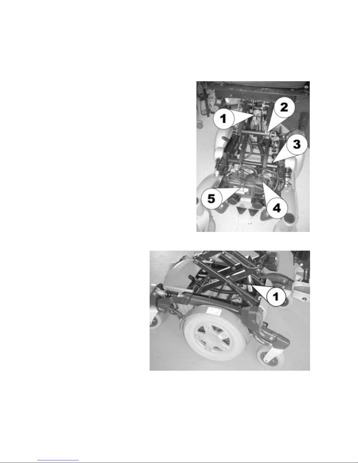
4 Layout of components and modules
The following image shows the Typhoon from above rear, with the seat lifter raised and the rear
cowling removed.
1 Seat tilt actuator
2 Seat-frame / rear cowling anti-collision switch
3 Speed-reduction switch
4 Power module
5 CLAM (Combined Light and Actuator Module)
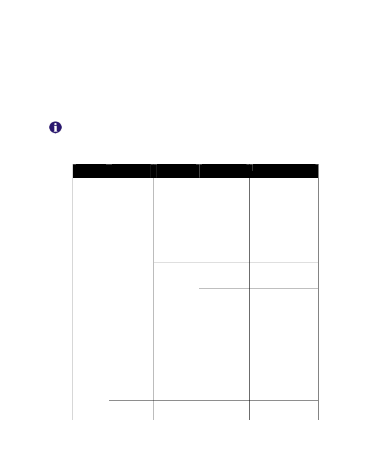
The following image shows the Typhoon from the front right, with the lifter raised
1 Lifter actuator

11
5 Service plan (1x annually)
Component Check Action Notes
9
Armrests and
side panels
• Armrest damage and
fastening
• Side panel damage
and fixing
⇒ Tighten screws, replace
padding if damaged
⇒ Tighten screws, replace
side panels if damaged
Seat unit / seat
angle adjustment
• Cushion
• Check seat angle
adjustment
⇒ Replace covers /
upholstery if damaged
⇒ Replace parts if damaged
Backrest unit
mechanical
Backrest unit
electrical
• Damage and seams
• Fixings
• Check cabling
• Check function
⇒ Replace parts if damaged
⇒ Tighten screws
⇒ Replace cable or motor if
necessary
Frame (chassis) /
battery box
• Check fixings, welded
seams and battery box
⇒ Tighten screws, replace
components
Wheel
suspension and
wheels
• Check drive wheels for
tight fit and side play
⇒ Adjust, replace wheel
hubs
See "Replacing a
drive wheel" on
page 55
• Check steering wheels
for tight fit, float, side
play and correct torque
(15 Nm +/- 1.5 Nm)
⇒ Replace wheels, wheel
fork or wheel bearings
See "Replacing
the steering head
bearings on the
front or rear castor
wheels" on page 47
• Check pneumatic tyres
on the drive wheels
⇒ Repair or replace if
damaged
See "Repairing a
flat tyre
(conventional
motor)" on page
52
Drive units,
disengager
• Check functions in
drive and push modes
• Check disengager
⇒ Replace motor if
necessary
⇒ Tighten screws / nuts,
adjust or replace if
necessary
Footrests
• Check welded seams,
interlocking, screws,
footplates
⇒ Tighten, replace if
necessary
Electrical
footrests
• Check cabling
• Check contacts
• Check functions
⇒ Replace cable if
necessary
Lighting
• Check cabling
• Check function
⇒ Replace bulbs or cables if
necessary
Batteries
• Check batteries for
damage
⇒ Replace batteries if
necessary
See "Replacing
the batteries" on
page 33
• Check battery charge ⇒ Charge batteries
See User Manual

12
Component Check Action Notes
9
• Check contacts and
terminals for corrosion
⇒ Clean contacts and
terminals
See "Replacing
the batteries" on
page 33 for Safety
Information on
working with
batteries
Remote /
electronics
• Remote,
status display blinking
• Fixing
• Cable, connecting plug
• Joystick function
• Power supply
⇒ Evaluate flash code
⇒ Tighten, replace
⇒ Replace
⇒ Replace joystick
⇒ Replace cable, connector
plug or console
Walking Beam
• Check spring for
damage
⇒ Replace if damaged
See "Replacing
the Anti-Dive
Spring" on page
50
Lifter
• Check correct function
• Check function of the
Stability Lock
⇒ Repair if necessary
Driving
Programme
• Check the programme
version of the driving
electronics. Is there a
newer version
available?
• Update the software.
See "Updating the "
on page 44
13
6 Troubleshooting the Typhoon
6.1 Troubleshooting the Typhoon with ACS
If a problem occurs with the wheelchair, then please proceed as follows:
• Identify the possible cause of the fault by using the troubleshooting tables below.
• Check the Status Display on the remote. Identify the error code if it is flashing.
• Perform the necessary checks and repairs as recommended in the table below.
Note
For more information on troubleshooting the Typhoon with GB motors, please see the “Dynamic
DX-GB-AS Power Module - Installation Manual”, Order Nr. 1441533
6.1.1 Diagnosing driving faults
PROBLEM OTHER
SYMPTOMS
POSSIBLE
CAUSE
SOLUTION REFERENCE
Wheelchai
r will not
drive
Status display
on remote
lights up
normally and
does not show
an error code
Drive motors
may be
disengaged
• Engage
the drive
motors
See User Manual
Status display
on remote
does not light
up
Batteries may
be defective
• Replace
the batteries
See "Replacing the
batteries" on page 33
Batteries may
be completely
discharged
• Charge
the batteries
See User Manual
Power supply
to the remote
may be
interrupted
• Check
the main fuse
See "Replacing the main
fuse" on page 39
• Check
cables
between
modules for
loose
connections or
damage
See "Checking the
cables" on page 41
Remote may
be defective
• Exchang
e the remote
on the
wheelchair for
a different one
to eliminate
the possibility
that the
remote may
be the cause.
See "Replacing the ACS
Remote" on page 42
Status display
on remote is
flashing
Various causes
• Identify
the error code
See "REM24 Error
Codes and Diagnostic
Codes" on page 16

14
PROBLEM OTHER
SYMPTOMS
POSSIBLE
CAUSE
SOLUTION REFERENCE
Status display
on remote
flashes 2x,
drive mode
display shows
"U"
Speed
reduction
switch on the
lifter may be
defective or
disconnected
• Replace
cable or
switch
See "Adjusting and
replacing the speed
reduction switch" on
page 46
Wheelchai
r does not
drive
smoothly
None Batteries may
be defective
(voltage not
stable)
• Replace
the batteries
See "Replacing the
batteries" on page 33
Drive motor(s)
may be
defective
• Replace
the drive
motor(s)
See "Replacing a
conventional drive
motor" on page 18 and
"Replacing and
calibrating a GB drive
motor" on page 22
Batteries
cannot be
charged
None Batteries may
be defective
• Replace
the batteries
See "Replacing the
batteries" on page 33
LEDs on the
charger are
flashing
Charger may
be defective
• Replace
the charger
See User Manual of the
charger
Wheelchai
r drives
too slowly
Status display
on remote
flashes 2x,
drive mode
display shows
"U"
Seat lifter is not
in driving
position (either
too high or too
low), and has
activated the
automatic
speed
reduction.
• Return
seat lifter to
driving
position
See User Manual
Speed-
reduction
micro-switch on
the seat lifter
may be badly
adjusted
• Adjust
the microswitch
See "Adjusting and
replacing the speed
reduction switch" on
page 46
None Remote may
be defective
• Replace
the remote
See "Replacing the ACS
Remote" on page 42
Batteries may
be defective
• Replace
the batteries
See "Replacing the
batteries" on page 33

15
6.1.2 Diagnosing problems with electric actuators
In case an electric actuator will not function, identify the source of the problem using the following
table:
PROBLEM OTHER
SYMPTOMS
POSSIBLE
CAUSE
SOLUTION REFERENCE
Electric
Actuator
does not
function
Remote
displays a
flashing "E",
status diode on
the CLAM does
not go out,
even if the
remote is
switched off or
disconnected
CLAM is
defective
• Replace
the CLAM
See "Replacing
components of the
electronics" on page 31
None Cable may
be
disconnected
or damaged
• Check
that the cable
is not
disconnected
or damaged. If
necessary,
replace the
cable
See "Checking the
cables" on page 41
Electric
actuator may
be defective
• Test the
actuator
See "Testing an actuator
motor" on page 45
Remote may
be defective
• Exchang
e the remote
on the
wheelchair for
a different one
to eliminate
the possibility
that the
remote may
be the cause.
See "Replacing the ACS
Remote" on page 42
16
6.1.3 REM24 Error Codes and Diagnostic Codes
The drive electronics are capable of rectifying some errors automatically. In this case the status
display will cease to flash. Please switch the remote on and off several times. Wait approx. 5
seconds each time before switching the remote on again. If this does not rectify the error, locate
the error using the flash codes shown below.
Flash code: Meaning: Solution: Notes
1 x flash
Module defective
• Replace defective module
See "Replacing
components of the
electronics" on page 31
2 x flashes
Accessory error
(e.g. actuator
short-circuit)
• Check accessory
connections, check
accessories
See "Testing an actuator
motor" on page 45
Lifter raised or
lowered too far
(seat not at driving
height)
• If lifter is raised, lower in
stages until the status
display stops flashing. If
lowered too far, raise lifter
in stages until the status
display stops flashing. If
at all possible, only drive
when the seat is at driving
height.
See User Manual
3 x flashes
Connection on the
left motor
loose/defective
• Check plug-in
connections.
See "Checking the
cables" on page 41
Left motor
defective.
• Check/replace motor
See "Replacing and
calibrating a GB drive
motor" on page 22
4 x flashes
Connection on the
right motor
loose/defective
• Check plug-in
connections.
See "Checking the
cables" on page 41
Right motor
defective.
• Check/replace motor
See "Replacing and
calibrating a GB drive
motor" on page 22
5 x flashes
Fault/brake fault
on left-hand motor.
Connection
loose/defective or
motor defective.
• Check plug-in
connections.
See "Checking the
cables" on page 41
Left motor
disengaged (GBmotors)
• Engage motor. Shut
electronics down and then
switch on again.
See User Manual
Both motors
disengaged
(standard motors)
• Engage motors. Shut
electronics down and then
switch on again.
See User Manual
6 x flashes
Fault/brake fault
on right-hand
motor. Connection
loose/defective or
motor defective.
• Check plug-in
connections.
See "Checking the
cables" on page 41
Right motor
disengaged (GBmotors)
• Engage motor. Shut
electronics down and then
switch on again.
See User Manual
7 x flashes
Battery dead
• Pre-charge battery
See User Manual
17
Flash code: Meaning: Solution: Notes
8 x flashes
Battery voltage too
high
• Switch lights on to lower
battery voltage
• Check battery charger
See User Manual of battery
charger
9 or 10 x
flashes
Faulty data
transmission
between modules
• -
Remove all electronic
modules except the Power
Module and the Remote.
Re-attach modules one by
one to determine which one
is causing the fault.
See "Replacing
components of the
electronics" on page 31
11 x flashes
Motors overloaded
/ overheated
• Switch remote on and off /
wait if necessary
-
12 x flashes
Module used has
compatibility
problems
• Remove incorrect module
See "Replacing
components of the
electronics" on page 31
 Loading...