

Invacare Twister, Twister-Junior Service Manual
Invacare® TWISTER
TWISTER-JUNIOR
SERVICE MANUAL
These instructions contain information
about:
Troubleshooting
Testing of Components
Repair
Edition: 10.2001

Twister/Twister Junior Service Manual
General information
These repair instructions contains all the information necessary for maintenance and overhaul
of both wheelchairs.
• Work which only applies to the Twister Junior is noted in the text.
• All maintenance and overhaul work must be carried out in accordance with these repair
instructions.
• Please observe all safety instructions.
• Information about operation or about general maintenance and care work should be taken
from the corresponding wheelchair Operating Manual.
• You can find information about complete replacement of the Twister Junior seating system in
the Twister Junior assembly instructions.
• You can find information about ordering spare parts in the spare parts catalogue.
• We reserve the right to make any alterations on the grounds of technical improvements.
• The wheelchair may only be maintained and overhauled by qualified personnel.
• The minimum requirement for service technicians is relevant training, such as in the cycle
or orthopaedic mechanics fields, or suitably long-term job experience.
Experience and knowledge of electrical measuring devices (Multimeter) is also a
requirement.
• If you have any problems or questions please contact INVACARE SERVICE:
Central office: Tel. +49 5731-754-0
Fax +49 5731-754-111
Service dept.: Tel. +49 5731-7545-(70-80)
Fax +49 5731-7542-(08-16)
Address: Invacare Deutschland GmbH
Dehmer Str. 66
32549 Bad Oeynhausen
PO Box: Invacare Deutschland GmbH
Postfach 60 01 06
32 527 Bad Oeynhausen
• Alterations to the wheelchair which occur as a result of incorrectly or improperly executed
maintenance or overhaul work lead to the exclusion of all liability on the side of INVACARE.
Twister / Twister Junior Service Manual
Issued: 21.01.02 Page 3
Notes on transport
• If the wheelchair has to be shipped back to the manufacturer for major repairs, you should
always use the original packaging for transport.
• You should also include as accurate a fault description as possible.
The following symbols are used in these repair instructions:
Note:
This symbol identifies general information which indicates special points or simplifications in
dismantling / reassembly.
Caution:
It is imperative that you observe any >safety instructions< identified with this symbol

Twister/Twister Junior Service Manual
Page 4 Issued:21.01.02
Contents
1 SAFETY AND ASSEMBLY INSTRUCTIONS 19
1.1 Before any inspection or repair work 19
1.2 During dismantling/reassembly 20
1.3 Before operation / after completion of work: 20
2 TOOL LIST 21
3 LAYOUT OF MODULES, COMPONENTS AND DISPLAYS AND
CONTROLS 22
4 ELECTRONIC CONTROL COMPONENTS (ACS) 26
4.1 General 26
4.2 Module connection cables 28
4.3 Sensors 28
4.4 Status displays 28
5 MODULE COMPOSITION 30
5.1 Wheelchair fittings: without lighting system, without actuators 30
5.2 Wheelchair fittings: with 24 V lighting system, without actuators 31
5.3 Wheelchair fittings: without lighting, with actuators 32
5.4 Wheelchair fittings: with 24 V lighting, with actuators 33
5.5 Wheelchair fittings: with 12 V lighting (TÜV Version), without actuators 34
5.6 Wheelchair fittings: with 12 V lighting (TÜV Version), with actuators 35
5.7 Wheelchair fittings: with electrically adjustable RECARO seat 36
6 INSPECTION PLAN 37
7 OPERATIONAL FAULTS 41
7.1 General 41
7.2 Fault causes 41
8 ERROR MESSAGE AT JOYSTICK BOX 44
8.1 Joystick box error codes 44

Twister / Twister Junior Service Manual
Issued: 21.01.02 Page 5
9 INSPECTION AND REPAIR WORK TO STANDARD SEATING
SYSTEMS 46
9.1 Armrests and side panels 46
9.1.1 Disassembly of armrests and side panels 47
9.1.2 Reassembly of armrests and side panels 47
9.2 Standard legrests without angle-adjustable footplate 48
9.2.1 Disassembly of legrests 49
9.2.2 Reassembly of legrests 49
9.3 Standard legrests with angle-adjustable footplate 50
9.3.1 Disassembly of legrests 51
9.3.2 Reassembly of legrests 51
9.4 Legrest, manually height-adjustable 52
9.4.1 Disassembly of legrests 54
9.4.2 Reassembly of legrests 54
9.5 Legrests, electrically height-adjustable 55
9.5.1 Disassembly of legrests 57
9.5.2 Reassembly of legrests 57
9.6 Legrest with one-piece footplate 58
9.6.1 Disassembly of legrests 59
9.6.2 Reassembly of legrests 59
9.7 Legrests with one-piece footplate for shorter lower legs 60
9.7.1 Disassembly of legrests 62
9.7.2 Reassembly of legrests 62
9.8 Legrests 73° and 90° 63
9.8.1 Disassembly of legrests 64
9.8.2 Reassembly of legrests 64
9.9 Headrest 65
9.9.1 Disassembly of headrest 66
9.9.2 Reassembly of headrest 66
9.10 Backrest anatomic element in standard, pin dot- and Dutch version 67
9.10.1 Disassembly of backrest element 68
9.10.2 Reassembly of the backrest elements 68
9.11 Backrest element, electrically adjustable, in standard and comfort version. 69
9.11.1 Disassembly of backrest element 71
9.11.2 Reassembly of the backrest elements 71
9.12 Backrest element, manually adjustable, in standard and comfort version 72
9.12.1 Disassembly of backrest element 73
9.12.2 Reassembly of the backrest elements 74
9.13 Expansion wedge 75
9.13.1 Disassembly of expansion wedge 75
9.13.2 Reassembly of the expansion wedge 75
10 TESTING AND REPAIR WORKS ON RECARO SEATING SYSTEM 76
10.1 General 76

Twister/Twister Junior Service Manual
Page 6 Issued:21.01.02
10.2 Headrest, safety belt and push handle 76
10.2.1 Disassembly of the headrest, the safety belt and the push handle 77
10.2.2 Disassembly of the headrest, the safety belt and the push handle 77
10.3 Armrests and side panels 78
10.3.1 Disassembly of armrests and side panels 79
10.3.2 Reassembly of armrests and side panels 79
10.4 Seating module and Frame 80
10.4.1 Disassembly of legrests 82
10.4.2 Reassembly of legrests 82
10.4.3 Disassembly of seat tilt adjustment 83
10.4.4 Reassembly of the seat tilt adjustment 83
10.4.5 Disassembly of the seating module and the seat frame 83
10.4.6 Reassembly of the seating module and the seat frame 83
11 TESTING AND REPAIR WORKS ON RECARO SEATING SYSTEM 84
11.1 General 84
11.2 Twister Junior headrest 85
11.2.1 Disassembly of headrest 86
11.2.2 Reassembly of headrest 86
11.3 Twister Junior backrest trunk supports 87
11.3.1 Disassembly of backrest trunk supports 88
11.3.2 Reassembly of backrest trunk supports 88
11.4 Electrical backrest adjustment, Twister Junior 89
11.4.1 Disassembly of actuator motor 90
11.4.2 Reassembly of actuator motor 90
11.5 Manual backrest adjustment, Twister Junior 91
11.5.1 Disassembly of backrest adjustment 92
11.5.2 Reassembly of backrest adjustment 92
11.6 Twister Junior armrests 93
11.6.1 Disassembly of armrests 95
11.6.2 Reassembly of armrests 95
11.7 Twister Junior backrest unit 96
11.7.1 Disassembly of the backrest unit 97
11.7.2 Reassembly of backrest unit 97
11.8 Expanding wedge for Twister Junior 98
11.8.1 Disassembly of the expanding wedge 98
11.8.2 Reassembly of expanding wedge 98
11.9 Twister Junior seating unit 100
11.9.1 Removal of seat unit 101
11.9.2 Reassembly of the seat unit 101
11.10 Footplate for Twister Junior 102
11.10.1 Disassembly of the footplate 103
11.10.2 Reassembly of footplate 103
11.11 Legrest upper part for Twister Junior 104
11.11.1 Disassembly of legrest upper parts 106
11.11.2 Reassembly of legrest upper parts 106

Twister / Twister Junior Service Manual
Issued: 21.01.02 Page 7
11.12 Legrest attachment for Twister Junior 107
11.12.1 Disassembly of legrest attachments 108
11.12.2 Reassembly of legrest attachments 108
11.13 Chin control and switch joystick for Twister Junior 109
11.13.1 Disassembly of the chin control and switch joystick 110
11.13.2 Reassembly of the chin control and switch joystick 110
12 TESTING AND REPAIR WORKS ON CHASSIS 111
12.1 Steering wheel suspension and steering wheels 8" x 2" 111
12.1.1 Disassembly of the steering wheel suspension and steering wheels 112
12.1.2 Reassembly of the steering wheel suspension and steering wheels 112
12.2 Splash protection for modules 113
12.2.1 Disassembly of "Standard" splash protection 113
12.2.2 Reassembly of "Standard" splash protection 113
12.2.3 Disassembly of the "Lifter" spray protection 113
12.2.4 Reassembly of "Lifter" splash protection 113
12.3 Drive wheels, tyres and wheel hubs 114
12.3.1 Disassembly of drive wheels and tyres 115
12.3.2 Reassembly of drive wheels and tyres 116
12.3.3 Dismounting of the wheel hubs 116
12.3.4 Reassembly of the wheel hubs 116
12.4 Drive unit complete 117
12.4.1 Dismounting the drive unit 121
12.4.2 Mounting the drive unit 121
12.5 Disengaging mechanism 122
12.5.1 Performance test of the disengaging mechanism 122
12.5.2 Adjusting the disengaging mechanism 123
12.5.3 Replacing the Star lock caps 123
12.6 Anti-tip mechanism 124
12.6.1 Disassembly of the anti-tip mechanism 124
12.6.2 Disassembly of the anti-tip mechanism 124
12.6.3 Disassembly of the anti-tip mechanism 124
13 CHANGES, TESTING AND REPAIR WORKS ON LIFTER UNIT 125
13.1 Changing the vehicle from front wheel to rear wheel drive 125
13.1.1 Converting the standard vehicle(without lifter) 125
13.1.2 Conversion of a vehicle with lifter 126
13.2 Conversion of the vehicle from rear wheel to front wheel drive 128
13.2.1 Converting the standard vehicle(without lifter) 128
13.2.2 Conversion of vehicle with lifter 129
13.3 Retrofitting the lifter module to current safety standards 131
13.3.1 Instructions for retrofitting the lifter module: 131
13.3.2 Final inspection 132
14 TESTING AND REPAIR WORKS ON POWER SUPPLY 133
14.1 Testing battery voltage and charge testing 133
14.1.1 "Testing the individual voltage of the batteries" 133
14.1.2 Checking total voltage of the batteries in non-operative state and under load 134

Twister/Twister Junior Service Manual
Page 8 Issued:21.01.02
14.2 30 Ah battery unit. 135
14.2.1 Disassembly of battery unit 136
14.2.2 Reassembly of the battery unit 136
14.3 40 Ah battery unit. 137
14.3.1 Disassembly of battery unit 138
14.3.2 Reassembly of the battery unit 138
14.4 Charge batteries. 139
14.4.1 General 139
14.4.2 Checks before charging 139
14.4.3 Charging procedure 140
14.4.4 Charging of fully discharged batteries 140
14.4.5 Performance test 141
15 TESTING AND REPAIR WORKS ON LIGHTING SYSTEM 142
15.1 Fault causes 142
15.2 Check lighting system 143
15.3 Disassemble / check headlight 144
15.3.1 Disassembly of headlights 144
15.3.2 Checking the headlights 144
15.3.3 Reassembly of headlights 145
15.4 Disassembling / checking rear lights 146
15.4.1 Disassembling rear lamps 146
15.4.2 Checking the rear lights 146
15.4.3 Reassembly of rear lights 146
15.5 Disassemble / check direction indicators 147
15.5.1 Disassembly of direction indicators 147
15.5.2 Checking the direction indicators 148
15.5.3 Reassembly of the direction indicators 148
15.6 Disassembling headlight / direction indicator unit completely 149
15.6.1 Disassembling the headlight 149
15.6.2 Reassembly of the headlight 149
15.6.3 Disassembly of the direction indicators 150
15.6.4 Reassembly of the direction indicators 150
15.6.5 Disassembly of the bulb holder 150
15.6.6 Reassembly of the bulb holder 150
15.7 Disassembling rear light and direction indicator unit completely 151
15.7.1 Disassembly of the rear light 151
15.7.2 Reassembly of the rear light 151
16 TESTING AND REPAIR WORK ON THE DRIVE UNIT 152
16.1 General 152
16.2 Performance check 152
16.3 Checking and replacing carbon brushes 152
16.3.1 Removing carbon brushes 153
16.3.2 Check carbon brushes 153
16.3.3 Refitting carbon brushes 153

Twister / Twister Junior Service Manual
Issued: 21.01.02 Page 9
16.4 Testing motor, magnetic brake and freewheel switch 154
16.4.1 Testing preparations / replacement of drive motors 154
16.4.2 Testing drive motor 154
16.4.3 Checking the magnetic brake 155
16.4.4 Checking the freewheel switch 155
17 TESTING AND REPAIR WORK ON THE ACTUATOR MOTORS 156
17.1 General 156
17.2 Checking the actuator motors 156
17.2.1 Visual inspection of the plug contacts: 156
17.2.2 Continuity check: 156
17.2.3 Performance test: 157
17.3 Replacing the actuator motors for the legrests 158
17.3.1 Disassembly 158
17.3.2 Reassembly 158
17.4 Replacing the seat adjustment actuator motor (without lifter module) 159
17.4.1 Disassembly 159
17.4.2 Reassembly 159
17.5 Replacement of seat adjustment (with lifter module) 160
17.5.1 Disassembly (Twister) 160
17.5.2 Reassembly (Twister) 160
17.5.3 Disassembly (Twister Junior) 160
17.5.4 Reassembly (Twister Junior) 160
17.6 Replacing actuator of automatic seat back adjustment or support tube for
manual seat back adjustment. 161
17.6.1 Disassembly 161
17.6.2 161
18 TESTING THE DRIVING ELECTRONICS 162
18.1 Overview of the electronic module and cable 162
18.2 Testing joystick boxes 164
18.2.1 Check power supply to joystick box 164
18.3 - Check power module. 166
18.3.1 Status display 166
18.3.2 Check power supply to power module. 167
Remove the battery cable plug from the power module. 167
18.4 Checking lighting modules or combined lighting / actuator module 168
18.4.1 Status display 168
18.4.2 Preparations for testing 168
18.4.3 Check the power supply from the power module to the lighting module 24V Æ 12V,
or to the lighting / actuator module 169
18.5 Testing additional power supply of lighting module 24V Æ 12V (TÜV version) 170
18.5.1 Preparations for testing 170
18.5.2 Test 170
18.6 Check the voltage converter for the Recaro seat 171
18.6.1 Preparations for testing 171
18.6.2 Checking voltage at Recaro seat voltage converter 171

Twister/Twister Junior Service Manual
Page 10 Issued:21.01.02
19 TESTING THE DRIVING ELECTRONICS 172
19.1 Standard joystick box 172
19.1.1 Disassembly of the standard joystick box 173
19.1.2 Reassembly of the standard joystick box 173
19.1.3 Disassembly joystick box support tube and joystick box attachment 173
19.1.4 Reassembly joystick box stay bar and joystick box attachment 173
19.1.5 Disassembly of the joystick box holder (hinged) 174
19.1.6 Reassembly of the joystick box holder (hinged) 174
19.1.7 Disassembly of the joystick box holder for attendant 174
19.1.8 Reassembly of the joystick box holder for attendant 174
19.2 Joystick box for attendant 175
19.2.1 Disassembly of joystick box 176
19.2.2 Reassembly of the joystick box 176
19.2.3 Disassembly of the joystick box holder 176
19.2.4 Reassembly of joystick box holder 176
19.3 Table control / central control 177
19.3.1 disassembly of joystick box 178
19.3.2 Reassembly of joystick box 178
19.3.3 Disassembly of central control support 178
19.3.4 Reassembly of central control support 178
19.3.5 Disassembly of table plate and support 179
19.3.6 Reassembly of table plate and support 179
19.4 Chin control, manually / electrically swivelling in horizontal direction 180
19.4.1 Disassembly of control 182
19.4.2 Reassembling the control 182
19.4.3 Disassembly of the motor 183
19.4.4 Reassembly of the motor 183
19.4.5 Disassembly of the switchbox 183
19.4.6 Reassembly of the switchbox 183
19.4.7 Disassembly of support, complete 183
19.4.8 Reassembly of support, complete 183
19.5 Chin control, electrically swivelling in vertical direction 184
19.5.1 Disassembly of control 185
19.5.2 Reassembling the control 185
19.5.3 Disassembly of the motor 185
19.5.4 Reassembly of the motor 185
19.5.5 Disassembly of the switchbox 186
19.5.6 Reassembly of the switchbox 186
19.5.7 Disassembly of support, complete 186
19.5.8 Reassembly of support, complete 186
19.6 Power module 187
19.6.1 Preparation 187
19.6.2 Removal of power module 187
19.6.3 Fitting the power module 187
19.7 Lighting and actuator module (Clam), lighting module and lighting module with
voltage converter 188
19.7.1 General 188
19.7.2 Removal of module 189
19.7.3 Refitting the module 189
20 CHECKING CABLES, PLUGS AND SENSORS 190
20.1 General 190

Twister / Twister Junior Service Manual
Issued: 21.01.02 Page 11
20.2 Test procedure 190
20.2.1 Checking plugs and cables 190
20.2.2 Checking the sensors 191
21 WHEELCHAIR PROGRAMMING 192
21.1 General 192
21.2 Programming on the PC 193
21.3 Programming with the programming device 194
22 STORING THE WHEELCHAIR 195
1 SAFETY AND ASSEMBLY INSTRUCTIONS 19
1.1 Before any inspection or repair work 19
1.2 During dismantling/reassembly 20
1.3 Before operation / after completion of work: 20
2 TOOL LIST 21
3 LAYOUT OF MODULES, COMPONENTS AND DISPLAYS AND
CONTROLS 22
4 ELECTRONIC CONTROL COMPONENTS (ACS) 26
4.1 General 26
4.2 Module connection cables 28
4.3 Sensors 28
4.4 Status displays 28
5 MODULE COMPOSITION 30
5.1 Wheelchair fittings: without lighting system, without actuators 30
5.2 Wheelchair fittings: with 24 V lighting system, without actuators 31
5.3 Wheelchair fittings: without lighting, with actuators 32
5.4 Wheelchair fittings: with 24 V lighting, with actuators 33
5.5 Wheelchair fittings: with 12 V lighting (TÜV Version), without actuators 34
5.6 Wheelchair fittings: with 12 V lighting (TÜV Version), with actuators 35
5.7 Wheelchair fittings: with electrically adjustable RECARO seat 36

Twister/Twister Junior Service Manual
Page 12 Issued:21.01.02
6 INSPECTION PLAN 37
7 OPERATIONAL FAULTS 41
7.1 General 41
7.2 Fault causes 41
8 ERROR MESSAGE AT JOYSTICK BOX 44
8.1 Joystick box error codes 44
9 INSPECTION AND REPAIR WORK TO STANDARD SEATING
SYSTEMS 46
9.1 Armrests and side panels 46
9.1.1 Disassembly of armrests and side panels 47
9.1.2 Reassembly of armrests and side panels 47
9.2 Standard legrests without angle-adjustable footplate 48
9.2.1 Disassembly of legrests 49
9.2.2 Reassembly of legrests 49
9.3 Standard legrests with angle-adjustable footplate 50
9.3.1 Disassembly of legrests 51
9.3.2 Reassembly of legrests 51
9.4 Legrest, manually height-adjustable 52
9.4.1 Disassembly of legrests 54
9.4.2 Reassembly of legrests 54
9.5 Legrests, electrically height-adjustable 55
9.5.1 Disassembly of legrests 57
9.5.2 Reassembly of legrests 57
9.6 Legrest with one-piece footplate 58
9.6.1 Disassembly of legrests 59
9.6.2 Reassembly of legrests 59
9.7 Legrests with one-piece footplate for shorter lower legs 60
9.7.1 Disassembly of legrests 62
9.7.2 Reassembly of legrests 62
9.8 Legrests 73° and 90° 63
9.8.1 Disassembly of legrests 64
9.8.2 Reassembly of legrests 64
9.9 Headrest 65
9.9.1 Disassembly of headrest 66
9.9.2 Reassembly of headrest 66
9.10 Backrest anatomic element in standard, pin dot- and Dutch version 67
9.10.1 Disassembly of backrest element 68
9.10.2 Reassembly of the backrest elements 68
9.11 Backrest element, electrically adjustable, in standard and comfort version. 69
9.11.1 Disassembly of backrest element 71
9.11.2 Reassembly of the backrest elements 71

Twister / Twister Junior Service Manual
Issued: 21.01.02 Page 13
9.12 Backrest element, manually adjustable, in standard and comfort version 72
9.12.1 Disassembly of backrest element 73
9.12.2 Reassembly of the backrest elements 74
9.13 Expansion wedge 75
9.13.1 Disassembly of expansion wedge 75
9.13.2 Reassembly of the expansion wedge 75
10 TESTING AND REPAIR WORKS ON RECARO SEATING SYSTEM 76
10.1 General 76
10.2 Headrest, safety belt and push handle 76
10.2.1 Disassembly of the headrest, the safety belt and the push handle 77
10.2.2 Disassembly of the headrest, the safety belt and the push handle 77
10.3 Armrests and side panels 78
10.3.1 Disassembly of armrests and side panels 79
10.3.2 Reassembly of armrests and side panels 79
10.4 Seating module and Frame 80
10.4.1 Disassembly of legrests 82
10.4.2 Reassembly of legrests 82
10.4.3 Disassembly of seat tilt adjustment 83
10.4.4 Reassembly of the seat tilt adjustment 83
10.4.5 Disassembly of the seating module and the seat frame 83
10.4.6 Reassembly of the seating module and the seat frame 83
11 TESTING AND REPAIR WORKS ON RECARO SEATING SYSTEM 84
11.1 General 84
11.2 Twister Junior headrest 85
11.2.1 Disassembly of headrest 86
11.2.2 Reassembly of headrest 86
11.3 Twister Junior backrest trunk supports 87
11.3.1 Disassembly of backrest trunk supports 88
11.3.2 Reassembly of backrest trunk supports 88
11.4 Electrical backrest adjustment, Twister Junior 89
11.4.1 Disassembly of actuator motor 90
11.4.2 Reassembly of actuator motor 90
11.5 Manual backrest adjustment, Twister Junior 91
11.5.1 Disassembly of backrest adjustment 92
11.5.2 Reassembly of backrest adjustment 92
11.6 Twister Junior armrests 93
11.6.1 Disassembly of armrests 95
11.6.2 Reassembly of armrests 95
11.7 Twister Junior backrest unit 96
11.7.1 Disassembly of the backrest unit 97
11.7.2 Reassembly of backrest unit 97
11.8 Expanding wedge for Twister Junior 98
11.8.1 Disassembly of the expanding wedge 98
11.8.2 Reassembly of expanding wedge 98

Twister/Twister Junior Service Manual
Page 14 Issued:21.01.02
11.9 Twister Junior seating unit 100
11.9.1 Removal of seat unit 101
11.9.2 Reassembly of the seat unit 101
11.10 Footplate for Twister Junior 102
11.10.1 Disassembly of the footplate 103
11.10.2 Reassembly of footplate 103
11.11 Legrest upper part for Twister Junior 104
11.11.1 Disassembly of legrest upper parts 106
11.11.2 Reassembly of legrest upper parts 106
11.12 Legrest attachment for Twister Junior 107
11.12.1 Disassembly of legrest attachments 108
11.12.2 Reassembly of legrest attachments 108
11.13 Chin control and switch joystick for Twister Junior 109
11.13.1 Disassembly of the chin control and switch joystick 110
11.13.2 Reassembly of the chin control and switch joystick 110
12 TESTING AND REPAIR WORKS ON CHASSIS 111
12.1 Steering wheel suspension and steering wheels 8" x 2" 111
12.1.1 Disassembly of the steering wheel suspension and steering wheels 112
12.1.2 Reassembly of the steering wheel suspension and steering wheels 112
12.2 Splash protection for modules 113
12.2.1 Disassembly of "Standard" splash protection 113
12.2.2 Reassembly of "Standard" splash protection 113
12.2.3 Disassembly of the "Lifter" spray protection 113
12.2.4 Reassembly of "Lifter" splash protection 113
12.3 Drive wheels, tyres and wheel hubs 114
12.3.1 Disassembly of drive wheels and tyres 115
12.3.2 Reassembly of drive wheels and tyres 116
12.3.3 Dismounting of the wheel hubs 116
12.3.4 Reassembly of the wheel hubs 116
12.4 Drive unit complete 117
12.4.1 Dismounting the drive unit 121
12.4.2 Mounting the drive unit 121
12.5 Disengaging mechanism 122
12.5.1 Performance test of the disengaging mechanism 122
12.5.2 Adjusting the disengaging mechanism 123
12.5.3 Replacing the Star lock caps 123
12.6 Anti-tip mechanism 124
12.6.1 Disassembly of the anti-tip mechanism 124
12.6.2 Disassembly of the anti-tip mechanism 124
12.6.3 Disassembly of the anti-tip mechanism 124
13 CHANGES, TESTING AND REPAIR WORKS ON LIFTER UNIT 125
13.1 Changing the vehicle from front wheel to rear wheel drive 125
13.1.1 Converting the standard vehicle(without lifter) 125
13.1.2 Conversion of a vehicle with lifter 126
13.2 Conversion of the vehicle from rear wheel to front wheel drive 128

Twister / Twister Junior Service Manual
Issued: 21.01.02 Page 15
13.2.1
Converting the standard vehicle(without lifter) 128
13.2.2 Conversion of vehicle with lifter 129
13.3 Retrofitting the lifter module to current safety standards 131
13.3.1 Instructions for retrofitting the lifter module: 131
13.3.2 Final inspection 132
14 TESTING AND REPAIR WORKS ON POWER SUPPLY 133
14.1 Testing battery voltage and charge testing 133
14.1.1 "Testing the individual voltage of the batteries" 133
14.1.2 Checking total voltage of the batteries in non-operative state and under load 134
14.2 30 Ah battery unit. 135
14.2.1 Disassembly of battery unit 136
14.2.2 Reassembly of the battery unit 136
14.3 40 Ah battery unit. 137
14.3.1 Disassembly of battery unit 138
14.3.2 Reassembly of the battery unit 138
14.4 Charge batteries. 139
14.4.1 General 139
14.4.2 Checks before charging 139
14.4.3 Charging procedure 140
14.4.4 Charging of fully discharged batteries 140
14.4.5 Performance test 141
15 TESTING AND REPAIR WORKS ON LIGHTING SYSTEM 142
15.1 Fault causes 142
15.2 Check lighting system 143
15.3 Disassemble / check headlight 144
15.3.1 Disassembly of headlights 144
15.3.2 Checking the headlights 144
15.3.3 Reassembly of headlights 145
15.4 Disassembling / checking rear lights 146
15.4.1 Disassembling rear lamps 146
15.4.2 Checking the rear lights 146
15.4.3 Reassembly of rear lights 146
15.5 Disassemble / check direction indicators 147
15.5.1 Disassembly of direction indicators 147
15.5.2 Checking the direction indicators 148
15.5.3 Reassembly of the direction indicators 148
15.6 Disassembling headlight / direction indicator unit completely 149
15.6.1 Disassembling the headlight 149
15.6.2 Reassembly of the headlight 149
15.6.3 Disassembly of the direction indicators 150
15.6.4 Reassembly of the direction indicators 150
15.6.5 Disassembly of the bulb holder 150
15.6.6 Reassembly of the bulb holder 150
15.7 Disassembling rear light and direction indicator unit completely 151
15.7.1 Disassembly of the rear light 151

Twister/Twister Junior Service Manual
Page 16 Issued:21.01.02
15.7.2
Reassembly of the rear light 151
16 TESTING AND REPAIR WORK ON THE DRIVE UNIT 152
16.1 General 152
16.2 Performance check 152
16.3 Checking and replacing carbon brushes 152
16.3.1 Removing carbon brushes 153
16.3.2 Check carbon brushes 153
16.3.3 Refitting carbon brushes 153
16.4 Testing motor, magnetic brake and freewheel switch 154
16.4.1 Testing preparations / replacement of drive motors 154
16.4.2 Testing drive motor 154
16.4.3 Checking the magnetic brake 155
16.4.4 Checking the freewheel switch 155
17 TESTING AND REPAIR WORK ON THE ACTUATOR MOTORS 156
17.1 General 156
17.2 Checking the actuator motors 156
17.2.1 Visual inspection of the plug contacts: 156
17.2.2 Continuity check: 156
17.2.3 Performance test: 157
17.3 Replacing the actuator motors for the legrests 158
17.3.1 Disassembly 158
17.3.2 Reassembly 158
17.4 Replacing the seat adjustment actuator motor (without lifter module) 159
17.4.1 Disassembly 159
17.4.2 Reassembly 159
17.5 Replacement of seat adjustment (with lifter module) 160
17.5.1 Disassembly (Twister) 160
17.5.2 Reassembly (Twister) 160
17.5.3 Disassembly (Twister Junior) 160
17.5.4 Reassembly (Twister Junior) 160
17.6 Replacing actuator of automatic seat back adjustment or support tube for
manual seat back adjustment. 161
17.6.1 Disassembly 161
17.6.2 161
18 TESTING THE DRIVING ELECTRONICS 162
18.1 Overview of the electronic module and cable 162
18.2 Testing joystick boxes 164
18.2.1 Check power supply to joystick box 164
18.3 - Check power module. 166
18.3.1 Status display 166
18.3.2 Check power supply to power module. 167
Remove the battery cable plug from the power module. 167

Twister / Twister Junior Service Manual
Issued: 21.01.02 Page 17
18.4 Checking lighting modules or combined lighting / actuator module 168
18.4.1 Status display 168
18.4.2 Preparations for testing 168
18.4.3 Check the power supply from the power module to the lighting module 24V Æ 12V,
or to the lighting / actuator module 169
18.5 Testing additional power supply of lighting module 24V Æ 12V (TÜV version) 170
18.5.1 Preparations for testing 170
18.5.2 Test 170
18.6 Check the voltage converter for the Recaro seat 171
18.6.1 Preparations for testing 171
18.6.2 Checking voltage at Recaro seat voltage converter 171
19 TESTING THE DRIVING ELECTRONICS 172
19.1 Standard joystick box 172
19.1.1 Disassembly of the standard joystick box 173
19.1.2 Reassembly of the standard joystick box 173
19.1.3 Disassembly joystick box support tube and joystick box attachment 173
19.1.4 Reassembly joystick box stay bar and joystick box attachment 173
19.1.5 Disassembly of the joystick box holder (hinged) 174
19.1.6 Reassembly of the joystick box holder (hinged) 174
19.1.7 Disassembly of the joystick box holder for attendant 174
19.1.8 Reassembly of the joystick box holder for attendant 174
19.2 Joystick box for attendant 175
19.2.1 Disassembly of joystick box 176
19.2.2 Reassembly of the joystick box 176
19.2.3 Disassembly of the joystick box holder 176
19.2.4 Reassembly of joystick box holder 176
19.3 Table control / central control 177
19.3.1 disassembly of joystick box 178
19.3.2 Reassembly of joystick box 178
19.3.3 Disassembly of central control support 178
19.3.4 Reassembly of central control support 178
19.3.5 Disassembly of table plate and support 179
19.3.6 Reassembly of table plate and support 179
19.4 Chin control, manually / electrically swivelling in horizontal direction 180
19.4.1 Disassembly of control 182
19.4.2 Reassembling the control 182
19.4.3 Disassembly of the motor 183
19.4.4 Reassembly of the motor 183
19.4.5 Disassembly of the switchbox 183
19.4.6 Reassembly of the switchbox 183
19.4.7 Disassembly of support, complete 183
19.4.8 Reassembly of support, complete 183
19.5 Chin control, electrically swivelling in vertical direction 184
19.5.1 Disassembly of control 185
19.5.2 Reassembling the control 185
19.5.3 Disassembly of the motor 185
19.5.4 Reassembly of the motor 185
19.5.5 Disassembly of the switchbox 186
19.5.6 Reassembly of the switchbox 186
19.5.7 Disassembly of support, complete 186
19.5.8 Reassembly of support, complete 186

Twister/Twister Junior Service Manual
Page 18 Issued:21.01.02
19.6 Power module 187
19.6.1 Preparation 187
19.6.2 Removal of power module 187
19.6.3 Fitting the power module 187
19.7 Lighting and actuator module (Clam), lighting module and lighting module with
voltage converter 188
19.7.1 General 188
19.7.2 Removal of module 189
19.7.3 Refitting the module 189
20 CHECKING CABLES, PLUGS AND SENSORS 190
20.1 General 190
20.2 Test procedure 190
20.2.1 Checking plugs and cables 190
20.2.2 Checking the sensors 191
21 WHEELCHAIR PROGRAMMING 192
21.1 General 192
21.2 Programming on the PC 193
21.3 Programming with the programming device 194
22 STORING THE WHEELCHAIR 195

Twister / Twister Junior Service Manual
Issued: 21.01.02 Page 19
1 Safety and assembly instructions
The safety instructions are intended as prevention of accidents at work and it is imperative that
they are observed.
1.1 Before any inspection or repair work
• Read and observe this repair manual and the associated operating manual.
• Observe the minimum requirements for carrying out the work. See the chapter entitled
“General
guidelines”.
Caution:
• Please note the high weight of some components. This applies especially to removal
of drive units and batteries.
• The wheelchair must be switched off before removal of voltage-carrying components.
To do this remove the battery.
• When making measurements on voltage-carrying components, avoid short-circuiting
the contacts.
Danger of fire and combustion !
• Use only undamaged tools in good condition.
Twister/Twister Junior Service Manual
Page 20 Issued:21.01.02
1.2 During dismantling/reassembly
• Mark all current settings for the wheelchair (seat, armrests, backrest etc.), and the cable
connecting plugs associated, before any removals. This makes reassembly easier.
Caution:
• Prop up the lifted wheelchair with appropriate supports before starting the
disassembly or assembly.
• Never use "normal" nuts instead of self-locking nuts.
• Never re-use self locking nuts, always replace with new.
• Always use correctly dimensioned washers or spacers.
Note:
• All plugs are fitted with mechanical safety devices which prevent release of
the connecting plugs during operation.
• To release the connecting plugs the safety devices must be pressed in.
• When reassembling ensure that these safety devices are correctly engaged.
• If the seating system is tipped forward for maintenance and service work,
it must be supported as necessary.
1.3 Before operation / after completion of work:
Caution:
• Check all fixings for tight fit.
• Check all parts for correct interlocking.
• Only operate wheelchair with correct tyre pressure (2.5 bar).
• As a last check always
carry out a trial run.

Twister / Twister Junior Service Manual
Issued: 21.01.02 Page 21
2 Tool list
You will need a standard tool set with at least the following:
• Open-end and ring spanner SW 6, 7, 8, 10, 11, 12, 13, 17, 19 (mm)
• Allen key 2.5, 3, 4, 5, 6, 8, 10 (mm)
• torque wrench (commercial)
• socket spanner set
• Screwdriver TX 40
• slot-headed screwdrivers (various)
• Phillips screwdriver No. 1, 2, 3
• oblique pliers
• flat-nosed pliers
• circle pliers
• pointed pliers
• plumber's wrench
• cable lug pliers
• wooden or plastic hammer
• tyre repair kit (commercial)
• tyre pressure indicator
• valve removal tool
• wheel bearing puller
• Multimeter with probes and various cable clips
• jump leads
• soldering iron 30 W
• hot-melt glue gun
• front wheel hub puller (available from INVACARE Service)
• circlip pliers for Star lock caps (commercial, e.g. Tigtemeyer)
For setting up the ACS Control there is need of:
• programming device Item No.: 6 001 450
• Software package Item No.: P10 076
(including interface cable and dongle)
Twister/Twister Junior Service Manual
Page 22 Issued:21.01.02
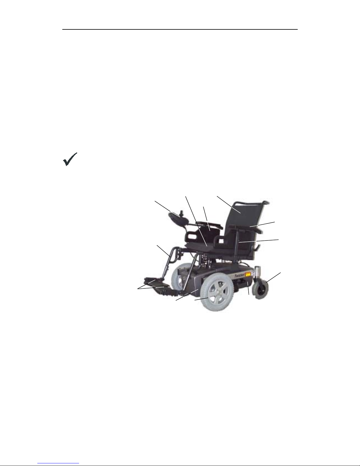
3 Layout of modules, components and displays and controls
The following illustrations show the general arrangement of the wheelchair's subassemblies,
components and control elements. The designations correspond to the component designations
in the spare parts catalogue.
The vehicles are available in different types, comprising the following main subassemblies:
• Chassis
• Seating system
• Power supply
• Drive control
• Lighting system
Note:
Depending on the type of wheelchair, the main subassemblies are equipped with
different subassemblies (legrests, control elements, seats, etc.).
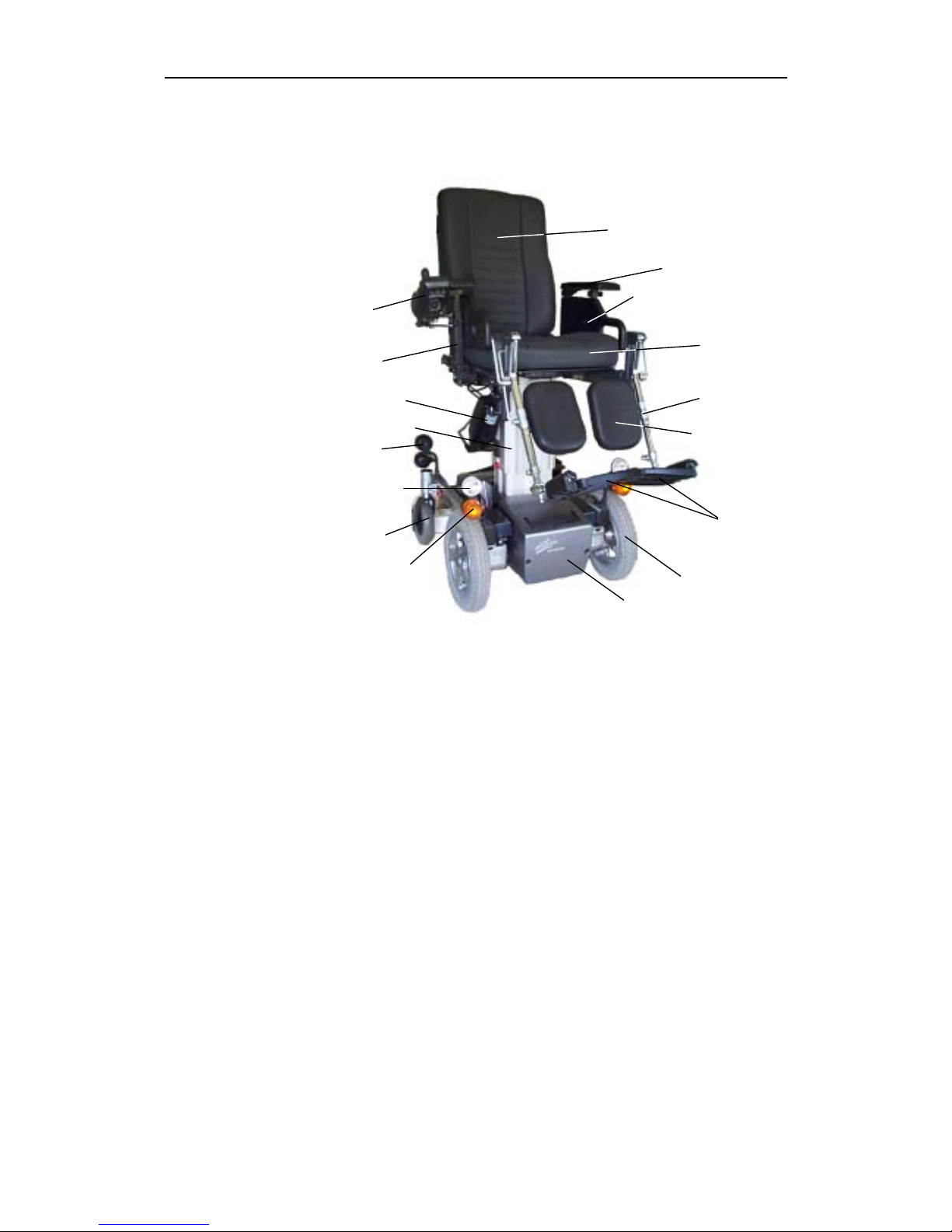
1. Seat cushion
2. Side panel
upholstery
3. Backrest upholstery
4. Armrest
5. Side panel
6. Rear wheel
7. Battery
8. Front wheel
9. Footplates
10.Legrest
11. Standard joystick
box
Standard "Twister" configuration,
front wheel drive, without lighting with standard seat attachments,
standard seat, standard backrest and 65°/73° legrests, without
headrests.
1
1
2
3
4
5
6
7
7
8
9
1
Twister / Twister Junior Service Manual
Issued: 21.01.02 Page 23
1. . Recaro seat
cushion
2. Side panel
upholstery
3. . Recaro backrest
upholstery
4. Armrest
5. Side panel
6. . Rear wheel,
complete
7. Batteries
8. . Front wheel,
complete
9. Footplates
10.Legrest, complete
11.Calf support
12.Lifter
13.. Motor for seat tilt
14.Rear lights
15.Headlights
16. Direction indicators
"Twister" configuration, side view
with Recaro seat, lifter(raised), front wheel drive, lighting system,
electrical. Backrest adjustment, electrical seat tilt, height and tiltadjustable footrests, swivelling joystick box and calf support without
headrests.
1
2
3
4
5
6
12
7
8
9
10
11
11
13
14
15
16
Twister/Twister Junior Service Manual
Page 24 Issued:21.01.02
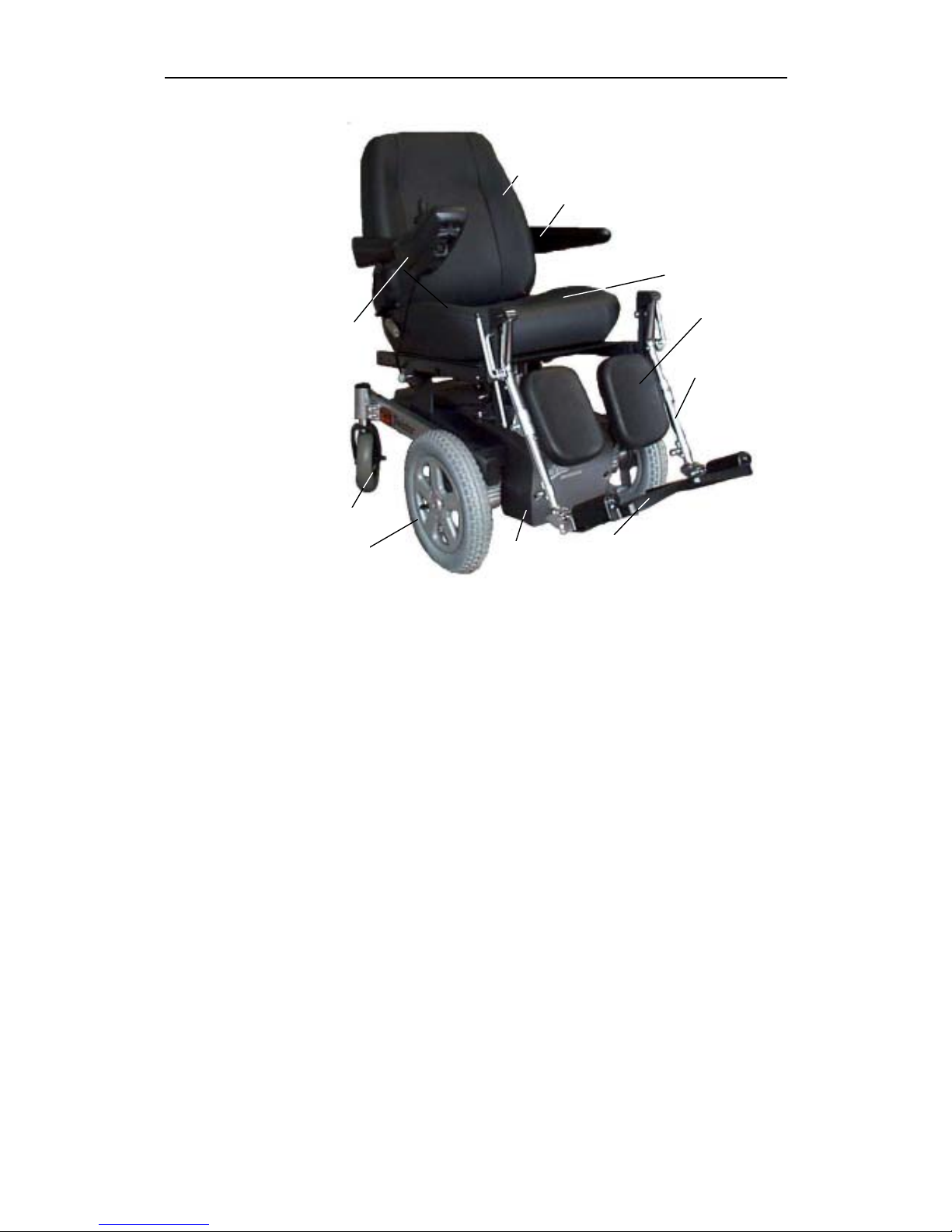
1. Seat cushion
2. Backrest upholstery
3. Armrest
4. Rear wheel
5. Battery
6. Front wheel
7. Footplates
8. Legrest
9. Standard joystick
box
10. Calf support
"Twister" configuration, front view
with KAB seat, front wheel drive, manually adjustable backrest,
manually adjustable seat tilting, height and tilt-adjustable footrests,
standard joystick box, calf support without headrests.
1
2
5
6
7
8
9
1
3
4
Twister / Twister Junior Service Manual
Issued: 21.01.02 Page 25
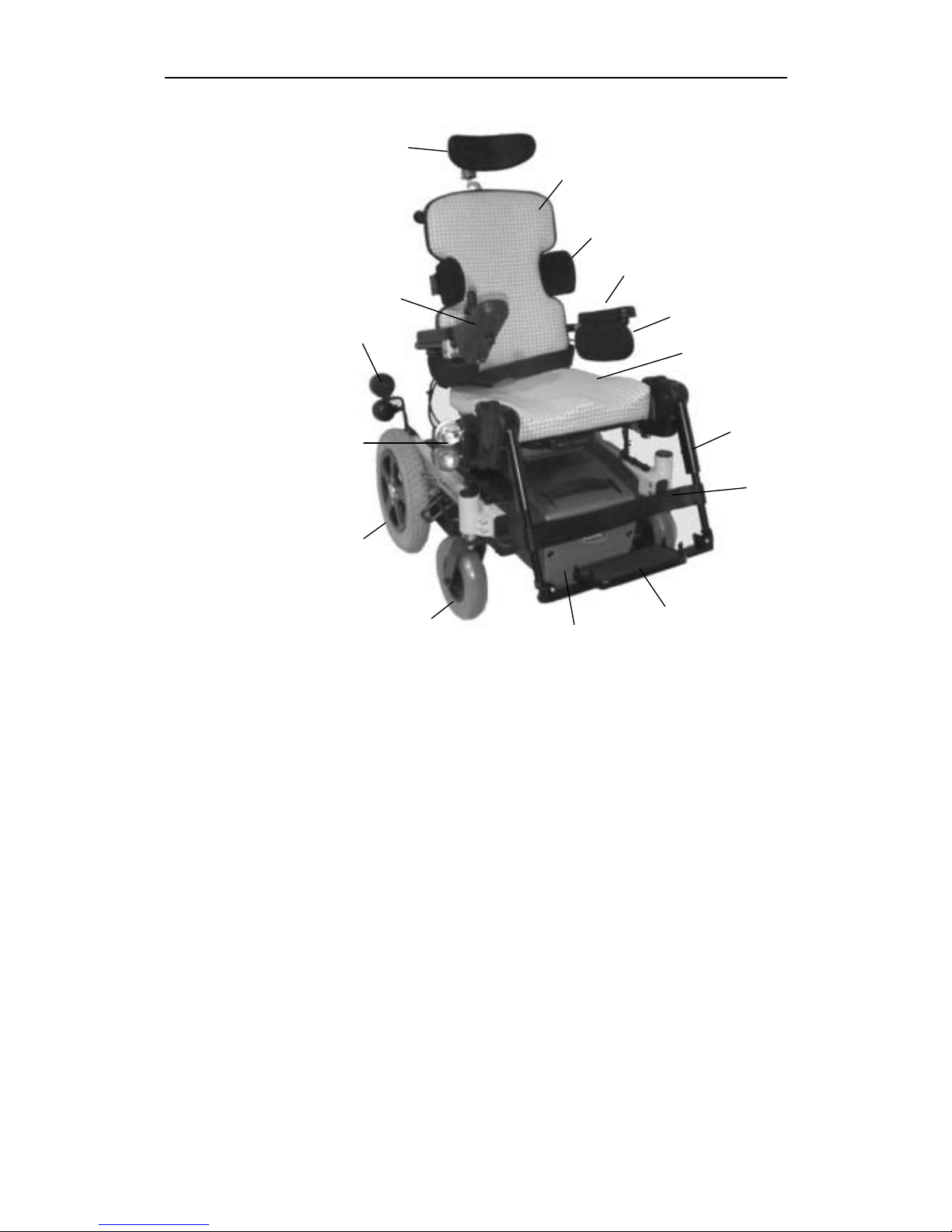
1. Seat cushion
2. Lateral trunk
support
3. Armrest with
upholstery
4. Backrest trunk
supports
5. Backrest upholstery
6. Headrest
7. Armrest with joystick
box
8. Rear lights and
direction indicators
9. Headlights and
direction indicators
10. Rear wheel
11. Front wheel
12. Battery
13. Footplate
14. Calf strap
15. Legrest
"Twister Junior" configuration with Junior seating system, rear
wheel drive, adjustable backrest, seat tilt, height and lean-adjustable
footplate, standard joystick box, calf strap and headrest:
1
2
4
3
6
7
8
10
11
12
13
14
15
5
9
Twister/Twister Junior Service Manual
Page 26 Issued:21.01.02
4 Electronic control components (ACS)
4.1 General
The wheelchair's electronic control ACS (Action Control System) is composed of individual
components (modules. According to type, the wheelchairs are equipped with different modules.
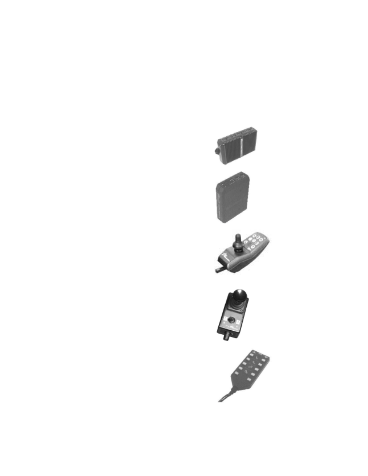
ACS Control module :
Module designation
(designation on module sticker)
Main module
(power module)
24 Volt lighting module lighting/actuator module
(combined lighting + actuator module)
Standard joystick box
(DX - REM 24)
joystick box for attendant
(DX - ACU 1AS)
Control unit for actuator motors
DX - ARC 5

Twister / Twister Junior Service Manual
Issued: 21.01.02 Page 27
Joystick box for table or central control
DX - REM 41 / REM 41 S
Chin control voltage converter
for Recaro seat
DX - ACC 1, or DC - DC converter
Standard joystick box for Twister Junior
(G - 80 - I)
Chin control and
switch joystick for Twister Junior
Apart from its controlling functions, the electronic control is in a position to perform the following
additional functions:
• Modules monitoring
• Actuator motor monitoring
• Drive system monitoring
• Fault diagnosis
Note:
The control unit for the Recaro seat's adjustment functions is integrated in the seat and
is not a part of the ACS.
Twister/Twister Junior Service Manual
Page 28 Issued:21.01.02
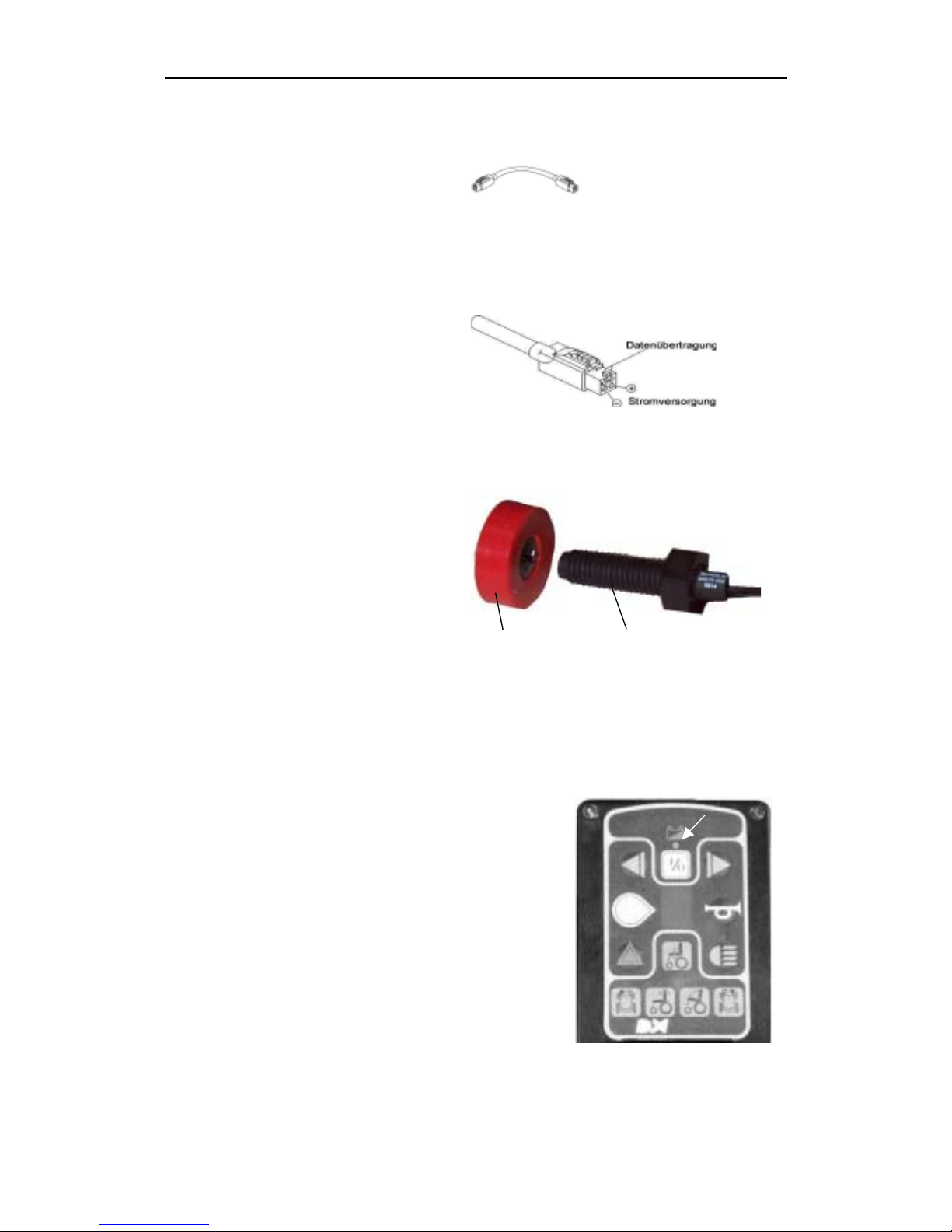
4.2 Module connection cables
The module connection cables are called
BUS cables. They are designed as fourconductor cables. Two conductors serve the
power supply and two the transfer of data.
Cable allocation
Power supply = black ground cable
red positive cable
Data transfer = yellow cable
(CAN high)
purple cable
(CAN low)
4.3 Sensors
The sensor unit consists of the sensor and a
magnet. If the magnet is closer than 1.5 cm
to the sensor tip, no electrical energy can
flow through the sensor.
In a vehicle with lifter, information is passed
using the sensor unit to the lifter positioning
control and the seat tilting.
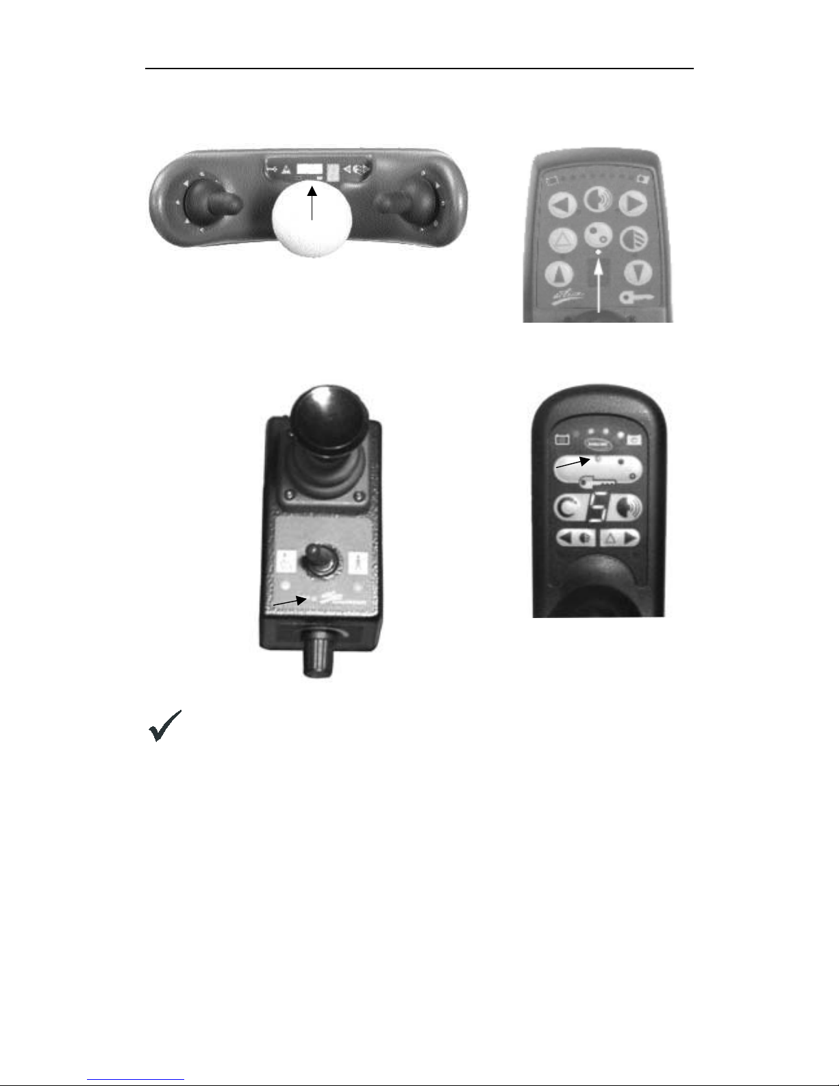
4.4 Status displays
Status displays are LEDs that point to errors in the
wheelchair's electrical installation by means of blinking.
The following joystick boxes have a status display:
• joystick box (standard)
• chin control
• table and central control
The ON/OFF LED's are designed as status displays. The
causes of trouble are displayed by a blinking interval (blinking
code) of these LED's.
The remaining modules are also equipped with status
displays. A blinking of these displays points to a module
error.
Table central control
BUS cable
BUS
Sensor unit
Magnet Sensor
Twister / Twister Junior Service Manual
Issued: 21.01.02 Page 29
Note:
The ACS is equipped with an error memory, which can be evaluated by means of a
commercially available PC. Additionally required hardware and software can be
obtained from INVACARE Deutschland GmbH under Item No.: P10 076.
Chin control
Standard-joystick
Standard-joystick
box
Joystick box for attendant
Twister/Twister Junior Service Manual
Page 30 Issued:21.01.02
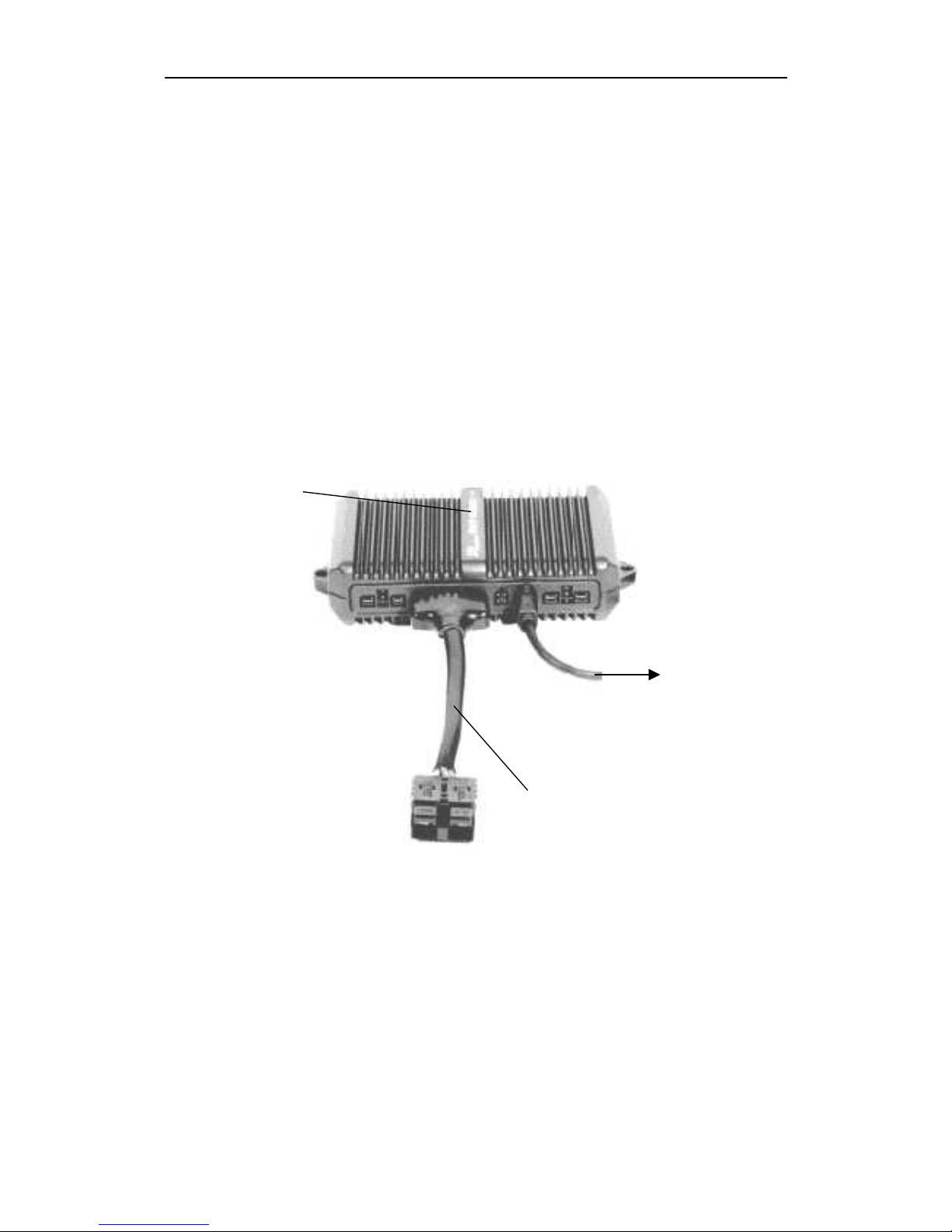
5 Module composition
The composition of modules depends on the type of wheelchair. The basic equipment consists
of the power module with its joystick box.
The joystick box can be used for any available module that is not older than the original joystick
box.
5.1 Wheelchair fittings: without lighting system, without actuators
Modules:
• Main module (power
module)
• Joystick box
Cables:
• BUS cable to joystick
box
• Battery cable
tojoystick box
Battery cable
Main
 Loading...