

Invacare TDX-SP, TDX-SP N Service Manual
Invacare ® TDX-SP / TDX-SP N
SERVICE MANUAL
Edition: 01.02.2013
SERVICE MANUAL
These instructions contain information about:
Testing work
Repair Instructions
This manual is part of the instructions for use.
Service addresses
Invacare
®
- TDX-SP / TDX-SP N
Invacare Austria GmbH
Herzog Odilostrasse 101
A-5310 Mondsee
Austria
Invacare n.v.
Autobaan 22
B-8210 Loppem (Brugge)
Belgium
Invacare AG
Benkenstraße 260
CH-4108 Witterswil
Switzerland
Invacare Aquatec GmbH
Alemannenstraße 10
88316 Isny
Deutschland
Invacare A/S
Sdr. Ringvej 37
DK-2605 Brøndby
Danmark
(: +43 6232 5 53 50
Fax: +43 6232 5 53 54
@: info@invacare-austria.com
WWW: www.invacare.at
(: +32 (0)50 83 10 10
Fax: +32 (0)50 83 10 11
@: belgium@invacare.com
WWW: www.invacare.be
(: +41 (0)61487 70 80
Fax: +41 (0)61487 70 81
@: switzerland@invacare.com
WWW: www.invacare.ch
( +49 (0)7562 70 00
Fax +49 (0)7562 7 00 66
@: info@invacare-aquatec.com
WWW: www.invacare-aquatec.de
( (Kundeservice): +45 (0)36 90 00 00
Fax (Kundeservice): +45 (0)36 90 00 01
@: denmark@invacare.com
WWW: www.invacare.dk
Invacare® SA
c/ Areny s/n
Polígon Industrial de Celrà
E-17460 Celrà (Girona)
ESPAÑA
Invacare® Poirier SAS
Route de St Roch
F-37230 Fondettes
France
Invacare® Ltd
Pencoed Technology Park
Pencoed
Bridgend CF35 5HZ
United Kingdom
Invacare Mecc San s.r.l .
Via dei Pini, 62
I - 36016 Thiene (VI)
Italia
2
(: +34 (0)972 49 32 00
Fax: +34 (0)972 49 32 20
@: contactsp@invacare.com
WWW: www.invacare.es
(: +33 (0)247 62 64 66
Fax: +33 (0)247 42 12 24
@: contactfr@invacare.com
WWW: www.invacare.fr
( (Customer services ): +44 (0)1656 77 62 22
Fax (Customer services): +44 (0)1656 77 62 20
@: uk@invacare.com
WWW: www.invacare.co.uk
(: +39 0445 38 00 59
Fax: +39 0445 38 00 34
@: italia@invacare.com
WWW: www.invacare.it
Invacare ® - TDX-SP / TDX-SP N
SERVICE MANUAL
Invacare Ireland Ltd.
Unit 5 Seatown Business Cam pus
Seatown Rd, Swords
County Dublin
Ireland
Invacare® AS
Grensesvingen 9
Postboks 6230
Etterstad
N-0603 Oslo
Norge
Invacare® B.V.
Celsiusstraat 46
NL-6716 BZ Ede
Nederland
Invacare Lda
Rua Estrada Velha, 949
P-4465-784 Leça do Balio
Portugal
(: +353 18 10 70 84
Fax: +353 18 10 70 85
@: ireland@invacare.com
WWW: www.invacare.ie
( (Kundeservice): +47 (0)22 57 95 00
Fax (Kundeservice): +47 (0)22 57 95 01
@: norway@invacare.com
@: island@invacare.com
WWW: www.invacare.no
(: +31 (0)318 69 57 57
Fax: +31 (0)318 69 57 58
@: nederland@invacare.com
@: csede@invacare.com
WWW: www.invacare.nl
(: +351 225 10 59 46
(: +351 225 10 59 47
Fax: +351 225 10 57 39
@: portugal@invacare.com
WWW: www.invacare.pt
Eastern
european
countries
Återförsäljare:
Invacare® AB
Fagerstagatan 9
S-163 91 Spånga
Sverige
Tillverkare:
Invacare® Deutschland GmbH
Kleiststraße 49
D-32457 Porta Westfal i ca
Deutschland
European Distributor
Organisation (EDO)
Kleiststraße 49
D-32457 Porta Westfal i ca
Deutschland
( (Kundtjänst): +46 (0)8 761 70 90
Fax (Kundtjänst): +46 (0)8 761 81 08
@: sweden@invacare.com
@: finland@invacare.com
WWW: www.invacare.se
MÖLNDAL
(: +46 (0)31 86 36 00
Fax: +46 (0)31 86 36 06
@: ginvacare@invacare.com
LANDSKRONA
(: +46 (0)418 2 85 40
Fax: +46 (0)418 1 80 89
@: linvacare@invacare.com
OSKARSHAMN
(: +46 (0)491 1 01 40
Fax: +46 (0)491 1 01 80
@: oinvacare@invacare.com
( +49 (0)5731 75 45 40
Fax +49 (0)5731 75 45 41
@: edo@invacare.com
WWW: www.invacare.de
3

SERVICE MANUAL
Invacare
®
- TDX-SP / TDX-SP N
Contents
Chapter Page
1 Introduction 7
1.1 General information .................................................................................................................. 7
1.2 Notes on transport .................................................................................................................... 7
1.3 Definition and representation of information and safety information in this manual ........ 8
1.4 Hazard symbols and symbols used ......................................................................................... 9
1.5 Images in this manual ............................................................................................................. 10
2 Safety and fitting instruct ions 11
2.1 Before any inspe ction or repair work .................................................................................... 11
2.2 Personal safety equipment ..................................................................................................... 11
2.3 General safety information and information about fitting / removal .................................. 11
3 Tightening torques 13
4 Layout of components and componentry 14
4.1 Overview ................................................................................................................................... 14
4.2 Electronic modules.................................................................................................................. 16
4.2.1 ACS 2 electronic module .............................................................................................. 18
4.2.2 ACS 2 PMA90L electronic module................................................................................ 18
4.2.3 Shark electronic module ............................................................................................... 18
4.2.3.1 Shark with DCI 12-pole ............................................................................................ 18
4.2.4 ACT actuator module .................................................................................................... 18
4.2.4.1 ACT 2 actuator module ............................................................................................ 19
4.2.4.2 ACT 4 actuator module ............................................................................................ 19
4.2.5 Lighting PCB ................................................................................................................. 19
5 Service plan (1x annually) 20
6 Operational f a ults 23
6.1 Drive fault diagnosis ............................................................................................................... 24
6.2 REM remotes: Error code s and diagnostic codes ............................................................... 28
6.3 Shark II remote: Error codes and diagnostic codes ............................................................ 30
6.4 Diagnosis of charging device faults ...................................................................................... 31
7 Test procedures 32
7.1 Testing the motor .................................................................................................................... 32
7.2 Testing the electro-mechanical parking brake ..................................................................... 33
8 Repair work 35
8.1 Covers without lifter ................................................................................................................ 35
8.1.1 Opening the front panel ................................................................................................ 35
8.1.2 Opening the rear cover panel ....................................................................................... 36
8.1.2.1 Rear cover without an operating hours counter ....................................................... 36
8.1.2.2 Rear cover with an operating hours counter ............................................................ 37
8.1.3 Opening the top cover panel ......................................................................................... 38
8.1.4 Replacing the splash guard .......................................................................................... 39
8.2 Electronic module.................................................................................................................... 40
8.2.1 Replacing the remote .................................................................................................... 40
8.2.2 Replacing the electronic module ................................................................................... 40
8.2.3 Replacing the G-Trac sensor ........................................................................................ 44
8.2.4 Replacing the operating hours counter / connecting cable ........................................... 45
8.2.5 Drive program selection after component replacement ................................................ 48
8.2.5.1 Profile selection with remote REM A or REM B ....................................................... 48
8.2.5.2 Profile selection with remote REM 550 .................................................................... 49
4

Invacare ® - TDX-SP / TDX-SP N
SERVICE MANUAL
Updating the driving program ................................................................................................ 50
8.3
8.4 Batteries, cables & battery charger ....................................................................................... 51
8.4.1 Making the batteries accessible .................................................................................... 51
8.4.2 Replacing batteries (Standard TDX SP) ....................................................................... 53
8.4.3 Replacing batteries / replacing battery cables (TDX-SP N) .......................................... 55
8.4.4 Correct handling of damaged batteries ......................................................................... 57
8.4.5 Checking and replacing the main fuse (Standard TDX-SP) ......................................... 58
8.4.6 Replacing the main fuse (TDX-SP N) ........................................................................... 59
8.4.7 Checking the cable ....................................................................................................... 60
8.4.8 Cable routing ................................................................................................................. 62
8.5 Battery carrier .......................................................................................................................... 63
8.6 Replacing the battery case ..................................................................................................... 64
8.7 Lighting unit ............................................................................................................................. 65
8.7.1 Replacing the front bulb ................................................................................................ 65
8.7.2 Replacing the front headlight complete ........................................................................ 66
8.7.3 Replacing the front bulbholder ...................................................................................... 68
8.7.4 Replacing the rear bulb ................................................................................................. 69
8.7.5 Replacing the rear light complete ................................................................................. 70
8.7.6 Replacing the rear bulbholder ....................................................................................... 71
8.8 Wheel forks front/rear ............................................................................................................. 72
8.8.1 Replacing the wheel fork............................................................................................... 72
8.8.2 Adjusting the wheel fork ................................................................................................ 74
8.8.3 Replacing the wheels on double-sided wheel forks ...................................................... 75
8.9 Drive wheels ............................................................................................................................. 76
8.9.1 Replacing the drive wheel ............................................................................................. 76
8.9.2 Replacing the tyre or inner tube .................................................................................... 77
8.9.2.1 Replacing pneumatic tyres ...................................................................................... 77
8.9.2.2 Replacing puncture-protected tyres ......................................................................... 79
8.9.2.3 Replacing puncture-proof tyres ................................................................................ 81
8.9.3 Replacing the drive wheel hub (Standard motor).......................................................... 82
8.9.4 Replacing the drive wheel hub (SSD motor) ................................................................. 83
8.10 Rear wheel suspension ........................................................................................................... 84
8.10.1 Removing the rear wheel suspension ........................................................................... 84
8.10.2 Removing the rear wheel suspension – alternative method ......................................... 86
8.10.3 Refitting the rear wheel suspension .............................................................................. 88
8.10.4 Refitting the rear wheel suspension – alternative method ............................................ 89
8.11 Rear springs ............................................................................................................................. 91
8.11.1 Removing the rear springs ............................................................................................ 91
8.11.2 Refitting the rear springs ............................................................................................... 93
8.12 Bottom walking beam ............................................................................................................. 95
8.13 Top walking beam ................................................................................................................... 96
8.13.1 Removing the top walking beam ................................................................................... 96
8.13.2 Refitting the top walking beam ...................................................................................... 98
8.14 Drive unit ................................................................................................................................ 100
8.14.1 Replacing the motor/transmission unit (Standard motor) ........................................... 100
8.14.2 Replacing the motor/transmission unit (SSD motor) .................................................. 102
8.14.3 Replacing or rotating the motor / gearbox unit sealing ring (SSD motor) ................... 104
8.14.4 Replacing the motor/transmission clutch (Standard Motor) ........................................ 106
8.14.5 Replacing the motor/transmission clutch (SSD Motor) ............................................... 108
8.14.6 Replacing the carbon brushes (SSD motor) ............................................................... 110
8.14.7 Replacing the carbon brushes (Standard motor) ........................................................ 112
8.15 Replacing the rubber bu m p er .............................................................................................. 114
8.16 Castor housing front ............................................................................................................. 115
8.17 Replacing tilt module / lifter module .................................................................................... 116
8.17.1 Replacing the tilt module (max. > 30°) (without a lifter) .............................................. 116
8.17.1.1 Replacing the tilt module microswitch.................................................................... 118
8.17.1.2 Replacing the tilt module angular sensor ............................................................... 120
8.17.2 Replacing the tilt module (max. < 30°) (without a lifter) .............................................. 121
8.17.3 Replacing the lifter / tilt module ................................................................................... 124
5

SERVICE MANUAL
Invacare
®
- TDX-SP / TDX-SP N
8.17.4 Replacing the tilt actuator ........................................................................................... 128
8.17.5 Replacing the lifter actuator ........................................................................................ 130
8.17.5.1 Method 1 - Removing the lifter actuator when the lifter is raised ........................... 130
8.17.5.2 Method 2 - Removing the lifter actuator when the lifter is lowered ........................ 132
8.18 Seat support ........................................................................................................................... 136
8.19 Centre-mounted legrest (e lectric & manual) ....................................................................... 138
8.19.1 Replacing the manually operated centre-mounted legrest ......................................... 138
8.19.2 Replacing the electrically operated centre-mounted legrest ....................................... 139
8.19.3 Replacing an electric legrest actuator ......................................................................... 141
8.19.4 Replacing the calf plate on the centre-mounted legrest (electric & manual) .............. 143
8.19.5 Replacing the foot plate on the centre-mounted legrest (electric & manual) .............. 144
8.20 Anti-tip system ....................................................................................................................... 145
8.20.1 Removing the gas cylinder .......................................................................................... 145
8.20.2 Repairing the gas cylinder .......................................................................................... 148
8.20.2.1 Replacing the guide block fixing or clamping support ........................................... 148
8.20.2.2 Replacing the guide bush ...................................................................................... 149
8.20.2.3 Replacing the gas cylinder ..................................................................................... 149
8.20.3 Refitting the gas cylinder ............................................................................................. 150
8.20.4 Replacing the setting screw ........................................................................................ 152
8.20.5 Adjusting the setting screw ......................................................................................... 155
9 Installing accessories 156
9.1 Replacing the safety belt ...................................................................................................... 156
9.2 Further accessories ............................................................................................................... 156
6

Invacare ® - TDX-SP / TDX-SP N
1 Introduction
1.1 General information
● Service and maintenance work must be carried out taking this service manual into account.
● It is imperative that you observe safety information.
● Information about operation or about general maintenance and care work on the mobility aid
should be taken from the operating manual.
● You can find information about ordering spare parts in the spare parts catalogue.
● Only use original Invacare® spare parts. The guarantee will become invalid if other spare parts
are used!
● We reserve the right to make any alterations on the grounds of technical improvements.
● The mobility aid may only be maintained and overhauled by qualified personnel.
● The minimum requirement for service technicians is suitable training, such as in the cycle or
orthopaedic mechanics fields, or sufficiently long-term job experience.
- Experience in the use of electrical measuring equipment (multimeters) is also a requirement.
- Special Invacare® training is recommended.
SERVICE MANUAL
● Alterations to the mobility aid which occur as a result of incorrectly or improperly executed
maintenance or overhaul work lead to the exclusion of all liability on the side of INVACARE.
● If you have any problems or questions please contact Invacare® Service.
1.2 Notes on transport
● If the mobility aid has to be shipped back to the manufacturer for major repairs, you should
always use the original packaging for transport.
● Please attach a precise description of the fault.
7
SERVICE MANUAL
to hazards which could lead to ma terial damage if they
Invacare
®
- TDX-SP / TDX-SP N
1.3 Definition and re presentation of inf ormation and safet y information in t his manual
Different types of information and signal words are used throughout this manual.
HAZARD!
The signal word "HAZ ARD!" refers to immediate hazards.
● The following lines in italics refer to actions which serve to avoid such hazards.
WARNING!
The signal word "WARNING!" refers to possibly-occurring hazards which can lead to
death or serious inj u ries if they are not avoided.
● The following lines in italics refer to actions which serve to avoid such hazards.
ATTENTION!
The signal word " ATTENTION!" refers to possibly-occur ring hazards which can lead to
minor injuries and/o r material damage if they are not avoided.
● The following lines in italics refer to actions which serve to avoid such hazards.
CAUTION!
The signal word "CAUTION!" refers
are not avoided.
● The following lines in italics refer to actions which serve to avoid such hazards.
Note
The signal word "Note" is used to denote general information which simplifies the handling of
your product and refers to special functions.
8
Invacare ® - TDX-SP / TDX-SP N
1.4 Hazard symbols and symbols used
Different types of hazard symbols and symbols are used throughout this manual.
General hazards
This symbol warns you of general hazards!
● Always follow the instructions to avoid injury to the user or damage to the product!
BURN HAZARD!
This symbol warns you of the danger of chemical burns, for example due to the discharge
of battery acids!
● Always follow the instructions to avoid injury to the user or damage to the product!
DANGER OF CRUSHING!
This symbol warns you of c rushing hazards due to inattentive working with heavy
components.
● Always follow the instructions to avoid injury to the user or damage to the product!
EXPLOSION HAZARD!
This symbol warns you of an explosion hazard, which can be caused by excessive tyre
pressure in a pneumatic tyre.
● Always follow the instructions to avoid injury to the user or damage to the product!
Wear safety shoes
The symbol refers to the requirement for wearing safety shoes.
● Wear standardised safety shoes during all work.
Wear eye protection
This symbol refers to th e requirement for wearing eye protection, for example when
working with batteries.
● Wear eye protection when this symbol is shown.
Wear safety gloves
This symbol refers to th e requirement for wearing safety gloves, for example when
working with batteries.
● Wear safety gloves when this symbol is shown.
Note
This symbol identifies general information which is intended to simplify working with your product
and which refers to special functions.
Requirements:
● This symbol identifies a list of various tools, components and items which you will need in
order to carry out certain work. Please do not attempt to carry out the work if you do not have
the listed tools available.
Always dispose used or damaged batteries correctly
The symbol refers to information for the correct disposal of used or damaged batteries.
SERVICE MANUAL
9

SERVICE MANUAL
1.5 Images in this manual
The detailed images in this manual are given digits to identify various components. Component
numbers in text and operational instructions always relate to the image directly above.
Invacare
®
- TDX-SP / TDX-SP N
10
Invacare ® - TDX-SP / TDX-SP N
SERVICE MANUAL
2 Safety and fitting instructions
These safety instructions are intended to prevent accidents at work, and it is imperative that they
are observed.
2.1 Before any inspection or repa ir wor k
● Read and observe this repair manual and the associated operating manual!
● Observe the minimum requirements for carrying out the work (see chapter entitled „General
information)!
2.2 Personal safety equipment
Safety shoes
The mobility device, and some of its components, are very heavy. These parts can result
in injuries to the feet i f th ey are allowed to drop.
● Wear standardised safety shoes during all work.
Eye protection
It is possible that batte ry acid can be discharged when working on defective batteries or
when handling batteries improperly.
● Always wear eye protection when working on any defective or possibly defective batteries.
Safety gloves
It is possible that batte ry acid can be discharged when working on defective batteries or
when handling batteries improperly.
● Always wear acid-proof safety gloves when working on any defective or possibly defective
batteries.
2.3 General safety information and informati on a bout f itting / removal
WARNING: Danger of crushing!
Various components such as the drive unit, batteries, seat etc are very heavy. This results
in injury hazards to your hands!
● Please note the high weight of some components! This applies especially to the removal of
drive units, batteries and the seat.
WARNING!
Injury hazard if the vehicle starts moving unintentionally during repair work!
● Switch the power supply off (ON/OFF key)!
● Engage the drive!
● Before raising the vehicle, secure the wheels by blocking them with wedges!
ATTENTION!
Fire and burn hazard due to electrical short-circuit!
● The mobility device must be completely switched off before removal of voltage-carrying
components! To do this, remove the batteries.
● Avoid short-circuiting the contacts when carrying out measurements on voltage-carrying
components!
11
SERVICE MANUAL
● Allow the motors to cool down before commencing work on them.
reassembling ensure that these safety devices are correctly engaged.
CAUTION!
Danger of burns from hot surfaces on the motor!
ATTENTION!
Injury hazard and danger of damage to vehicle due to improper or incomplete
maintenance work!
● Use only undamaged tools in good condition.
● Some moving parts are mounted in sockets with PTFE coating (Teflon™). Never grease these
sockets!
● Never use "normal" nuts instead of self-locking nuts.
● Always use correctly-dimensioned washers and spacers
● When reassembling, always replace any cable ties which were cut during dismantling.
● After completing your work / before renewed start-up of the mobility device, check all
connections for tight fitting.
● After completing your work / before renewed start-up of the mobility device, check all parts for
correct locking.
● Only operate the vehicle with the approved tyre pressures (see technical data).
● Check all electrical components for correct function. Please note that incorrect polarity can
result in damage to the electronics.
● Always carry out a trial run at the end of your work.
CAUTION!
Danger of injury an d d amage to property, if the maxim u m speed reduction on a
wheelchair with a lifter does not function correctly!
The wheelchair’s control uni t m u st reduce the maximum possible sp eed as soon as the
lifter is raised.
● Test the maximum speed reduction for correct function after any maintenance work or
modifications to the wheelchair.
Note
Mark all current settings for the mobility aid (seat, armrests, backrest etc.), and the associated
cable connecting plugs, before dismantling. This makes reassembly easier.
All plugs are fitted with mechanical safety devices which prevent release of the connecting plugs
during operation. To release the connecting plugs the safety devices must be pressed in. When
Invacare
®
- TDX-SP / TDX-SP N
WARNING!
Any changes to the drive program can affect the driving characteristics and the tipping
stability of the vehicle!
● Changes to the drive program may only be carried out by trained Invacare® specialist
dealers!
● Invacare® supplies all mobility aids with a standard drive program ex-works. Invacare® can
only give a warranty for safe vehicle driving behaviour - especially tipping stability - for this
standard drive program!
12

Invacare ® - TDX-SP / TDX-SP N
3 Tightening torques
The tightening torques stated in the following list are based on the thread diameter for the nuts and
bolts for which no specific values have been determined. All values assume dry and de-greased
threads.
SERVICE MANUAL
Thread
Tightening torque
in Nm ±10%
M4 M5 M6 M8 M10 M12 M14 M16
3 Nm 6 Nm 10 Nm 25 Nm 49 Nm 80 Nm 120 Nm 180 Nm
CAUTION!
Damage can be caused to the mobility device due to improperl y tightened screws, nuts or
plastic connections.
● Always tighten screws, nuts etc to the stated tightening torque.
● Only tighten screws or nuts which are not listed here fingertight.
13
SERVICE MANUAL
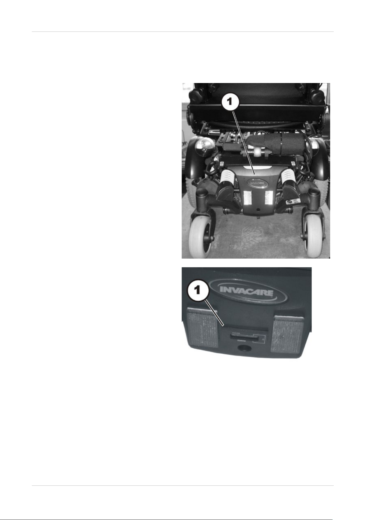
At rear underneath seat:
In rear cover:
Invacare
4 Layout of components and componentry
4.1 Overview
Electronic modules
The electronic modules are located
underneath the rear cover panel (1).
The electronic modules used are
described in Chapter 4.2.
®
- TDX-SP / TDX-SP N
(1) – Operating hours counter (optional)
14
Invacare ® - TDX-SP / TDX-SP N
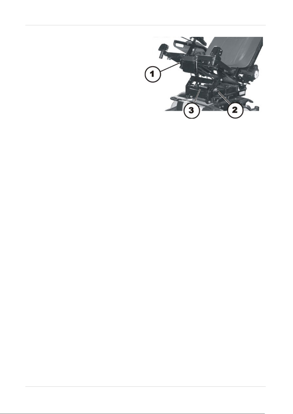
At the front, underneath the seat:
(1) – actuator module (optional)
(2) – lifter actuator (optional)
(3) – tilt actuator (optional)
SERVICE MANUAL
15
SERVICE MANUAL
ACS 2
REM 24
Shark
Shark II remote
ACT actuator
The actuator module
Lighting PCB
The lighting PCB is
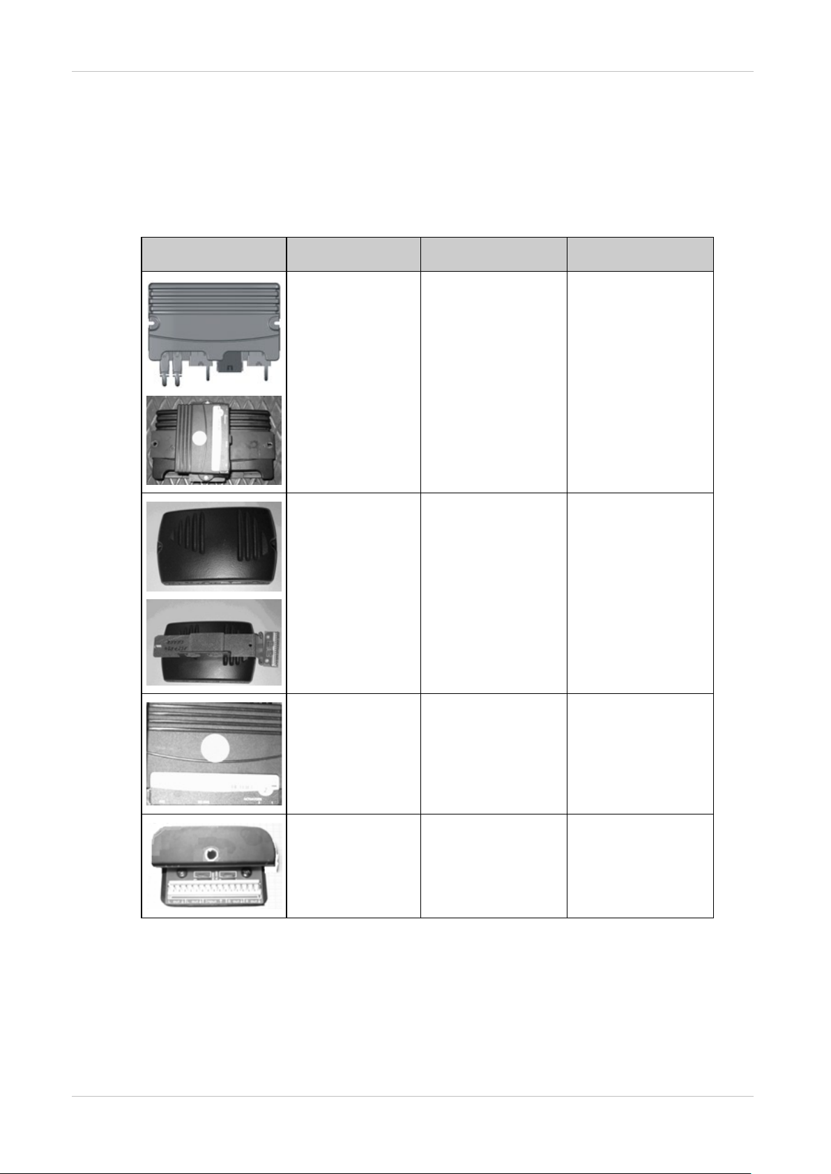
4.2 Electronic modules
A variety of electronic modules can be fitted to the mobility aid.
Before you connect any mobility aid components such as adjusting motors/actuators or motors to
the electronic modules, you should first ensure that you know exactly which electronic module has
been fitted. Please refer to the following table for an overview.
Electronic module Designation Joystick boxes Notes
Invacare
®
- TDX-SP / TDX-SP N
ACS 2 PMA90L
ACS 2 ACT
actuator module
Shark with lighting
PCB
REM A
REM B
REM 550
The actuator module
is optional.
The lighting PCB is
optional.
16
module
is optional.
optional.
Invacare ® - TDX-SP / TDX-SP N
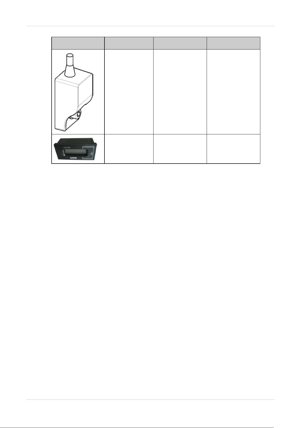
G-Trac sensor
The G-Trac sensor is
Operating hours
The operating hours
Electronic module Designation Joystick boxes Notes
SERVICE MANUAL
optional
counter
counter is optional.
17
SERVICE MANUAL
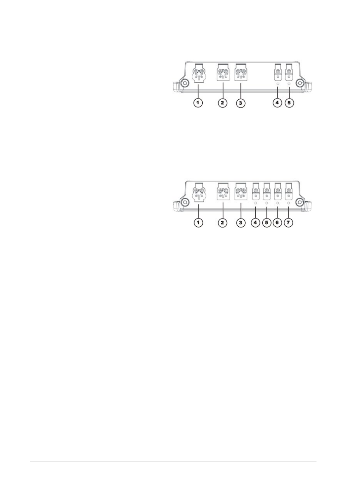
Connections
2) & 3) Order number: 1552876
Connections
Connections
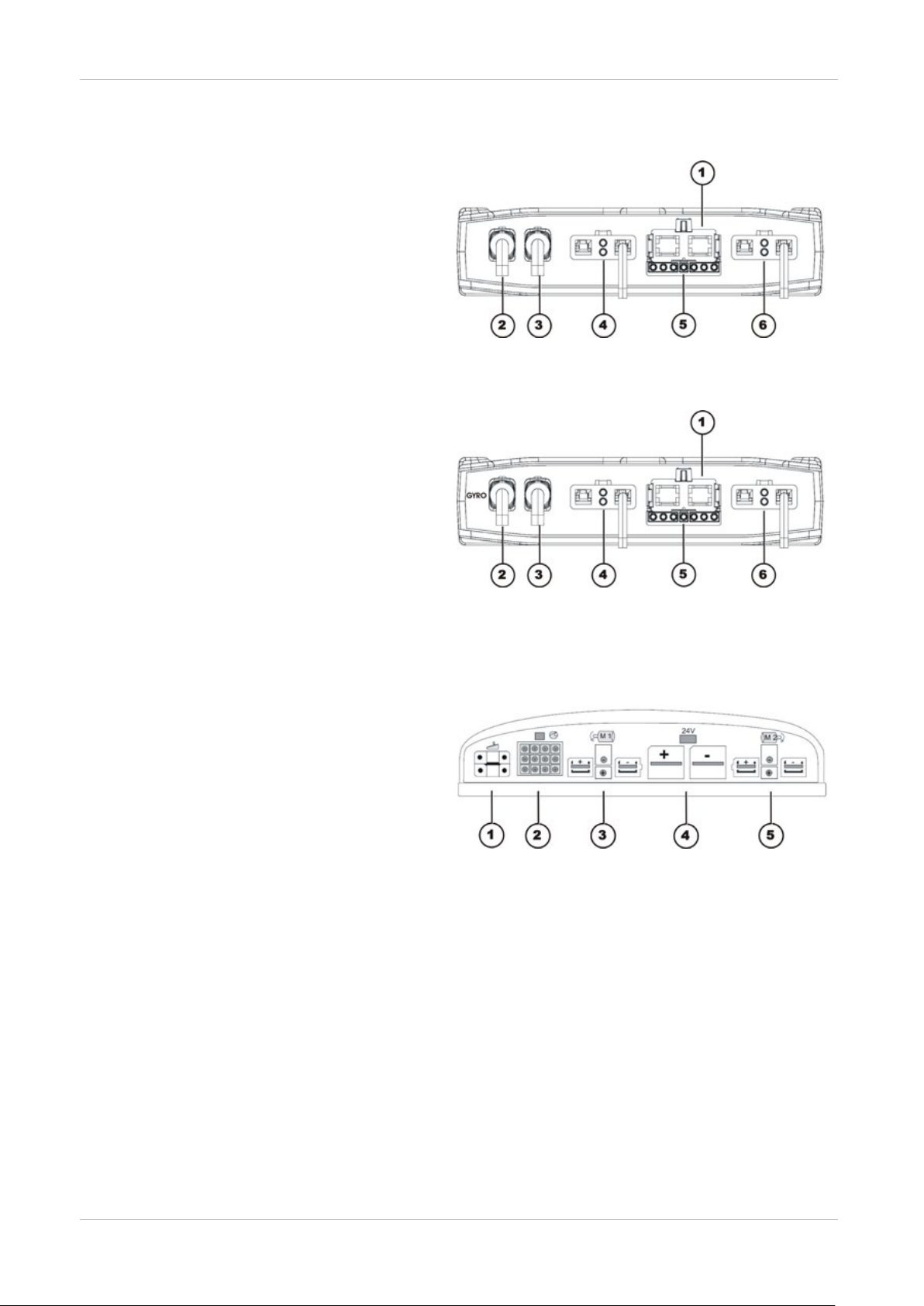
4.2.1 ACS 2 electronic module
1) Battery 24V
2) Bus cable (to remote or ACT)
3) Bus cable (to remote or ACT)
4) Motor M1
5) Light
6) Motor M2
Rubber stoppers for free slots
4.2.2 ACS 2 PMA90L electronic module
1) Battery 24V
2) Cable to G-Trac sensor (GYRO)
3) Bus cable (to remote or ACT)
4) Motor M1
5) Light
6) Motor M2
Invacare
®
- TDX-SP / TDX-SP N
4.2.3 Shark electronic module
4.2.3.1 Shark with DCI 12-pole
1) Cable to remote
2) DCI for actuators/lighting (12-pole)
3) Right-hand motor M1
4) Battery 24V
5) Left-hand motor M2
4.2.4 ACT actuator module
A range of adjusting motors, also known as actuators, can be fitted to the mobility aid. These
actuators are either connected directly to the electronic module or to a separate actuator module.
The actuator module is connected with the electronic module via a bus cable.
18
Invacare ® - TDX-SP / TDX-SP N
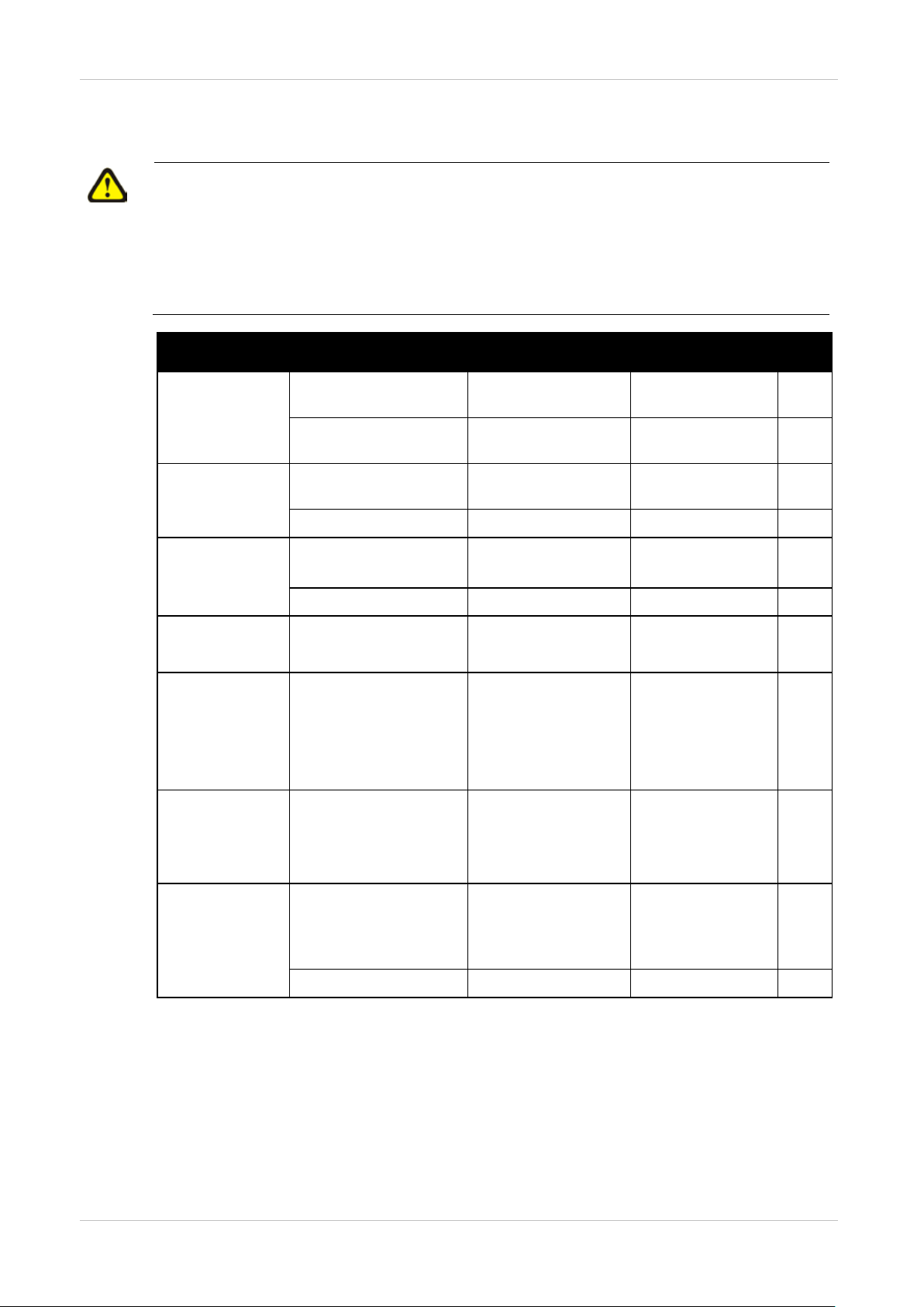
Connections
Connections
4.2.4.1 ACT 2 actuator module
1) ACI*
2) Bus cable (to remote or ACT)
3) Bus cable (to remote or ACT)
4) Adjusting motor/actuator - Channel 2
5) Adjusting motor/actuator - Channel 1
Rubber stoppers for free slots
1) Order number: 1555701
2) & 3) Order number: 1552876
4) & 5) Order number: 1555700
* The ACI connection is used for actuator limitation or speed reduction.
4.2.4.2 ACT 4 actuator module
1) ACI*
2) Bus cable (to remote or electronic
module)
3) Bus cable (to remote or electronic
module)
4) Actuator - Channel 4
5) Actuator - Channel 3
6) Actuator - Channel 2
7) Actuator - Channel 1
Rubber stoppers for free slots
1) Order number: 1555701
2) & 3) Order number: 1552876
4) to 7) Order number: 1555700
SERVICE MANUAL
* The ACI connection is used for actuator limitation or speed reduction.
4.2.5 Lighting PCB
The lighting PCB connections are printed directly on the circuit board.
19
SERVICE MANUAL
ü
5 Service plan (1x annually)
CAUTION!
Danger of injury and damage to property, if the maximum speed reduction on a
wheelchair with a lifter does not function correctly!
The wheelchair’s control uni t m u st reduce the maximum possible sp eed as soon as the
lifter is raised.
● Test the maximum speed reduction for correct function after any maintenance work or
modifications to the wheelchair.
Component Check Remedy Notes
Invacare
®
- TDX-SP / TDX-SP N
Safety belt
Armrests
Side panels
Seat angle
adjustment
Power backrest
(if fitted)
Frames
(chassis) /
battery
mounting
Damage to safety belt Replace belt if
See chapter 9.1.
damaged.
Belt lock function Replace belt if
See chapter 9.1
damaged.
Damage to armrests Replace covering if
damaged
Armrest fixings Tighten screws
Damage to side panels Replace side panels if
damaged
Side panel fixings Tighten screws
Tight seating of SL
fuses
Damage to backrest
Seams
Fixing
Check cable
Check function
Check fixings, welded
seams and battery
mounting
Replace SL fuses if
necessary
Replace parts if
damaged
Tighten screws
Replace cable motor
if necessary
Tighten screws
Replace components
if necessary
Anti-tip system
Check gas cylinder Repair or replace if
See chapter 8.20
damaged
Replace gas cylinder
every 2 years!
Check adjustment Speed See chapter 8.20.5.
20

Invacare ® - TDX-SP / TDX-SP N
ü
Component Check Remedy Notes
SERVICE MANUAL
Wheel
suspension and
wheels
Drive units,
clutch
mechanism
Check drive wheels for
tight fit and side play
Check steering wheels
for tight fit, float and
side play
Adjust, replace wheel
hubs
Replace wheels,
wheel fork or wheel
bearings
Tyres Repair or replace if
damaged
Check suspension Repair or replace if
damaged
Check straight running Replace wheels,
wheel fork or wheel
bearings
Motors
Check motors See chapter 7.
Check functions in drive
and push modes
Check clutch
mechanism
Check carbon
brushes, replace if
necessary
Replace motor if
necessary.
Tighten screws/nuts,
adjust or replace if
necessary
See chapters 8.9.1
and 8.9.3/8.9.4
See chapter 8.9
See chapter 8.9.2.
See chapter 8.11
See chapter 8.8.
See chapter 8.14
Brakes
Legrests
Power legrests
(if fitted)
Lighting (if
fitted)
Battery
mounting
Inspect motor brake Check motor brake See chapter 7.2.
Check welded seams,
interlocking, screws,
Tighten, replace if
necessary
footplates
Check cable
Check contacts
Replace cable if
necessary
check functions
Check cable
Check function
Check battery support
Replace lamp or
See chapter 8.7.
cable if necessary
Replace if necessary
and mounting belts for
damage
21

SERVICE MANUAL
ü
Component Check Remedy Notes
Invacare
®
- TDX-SP / TDX-SP N
Batteries
Remote /
electronic
module
Check batteries for
damage
Replace batteries if
necessary
See chapters
8.4.2/8.4.3 and
8.4.4
Check battery voltage Charge batteries
Check battery voltage Charge batteries See operating
manual
Check contacts and
terminals
Clean contacts and
terminals
Please refer to the
safety information
in Chapter
8.4.2/8.4.3 and
8.4.4 for handling
batteries
Remote, status display
blinking
Fixings Tighten fixings,
Evaluate error/blink
code
See chapter 6.
replace if necessary
Cables and connecting
plugs
Tighten cables and
connecting plugs,
replace if necessary
Drive lever function Replace drive lever if
necessary
Replace remote if
necessary
Power supply Tighten cables and
connecting plugs,
replace if necessary
Drive program
Check drive electronic
program version
Update software if
newer version
See chapter 8.3.
available.
22

Invacare ® - TDX-SP / TDX-SP N
You can obtain the original manuals from Invacare®.
6 Operational faults
The various electronic modules can be fitted in connection with differing remotes in the mobility aid.
Rectification of operational faults is dependent on the electronic module fitted.
The electronic modules used are described in Chapter 4.2.
Note
The tables for rectification of operational faults listed in the following chapters are only an excerpt
from the original manufacturer's manuals.
If you have problems with the mobility aid, please proceed as follows:
● First assess the possible cause of the problem using the following table.
● Check the remote status display. Evaluate the error code.
● Carry out the necessary checks and repairs as recommended in the following table.
SERVICE MANUAL
23

SERVICE MANUAL
None
electronic module
6.1 Drive fault diagnosis
Invacare
®
- TDX-SP / TDX-SP N
PROBLEM OTHER
SYMPTOMS
Mobility aid
will not start
The remote
status display
illuminates
normally and
displays blink
code 5/6.
Remote status
display does not
illuminate
Remote status
display blinking
POSSIBLE
SOLUTION DOCUMENTATION
CAUSE
Drive motors
disengaged
Batteries
defective
Completely
discharge battery
Power supply to
remote
interrupted
Engage drive
motors
See operating
manual
Replace batteries See chapter
8.4.2/8.4.3.
Pre-charge
batteries
Check master
fuse
Check cables
See operating
manual
See chapter
8.4.5/8.4.6.
See chapter 8.4.7.
between the
modules for loose
connections and
damage
Remote defective Replace remote See chapter 8.2.1.
Various causes Assess error code See chapter 6.2
and 6.3.
Mobility aid
judders in
drive mode
Mobility aid
pulls to left or
right
Error
message
does not go
out
Motors stop
and start
irregularly
Batteries
Replace batteries See chapter
defective
(unstable voltage)
Drive motor(s)
Replace motor(s) See chapter
defective
Replace carbon
brushes
None Drive motors
running
asymmetrically
Change
programming to
synchronise
motors.
None Bad connections Check all
connecting
cables.
Motor brake
defective
Measure internal
resistance of
brakes, replace
motor if defective.
None Voltage decline Stop journey and
allow electronic to
cool down.
8.4.2/8.4.3.
8.14.1/8.14.2.
See chapter
8.14.6/8.14.7.
See chapter 8.3.
See chapter 8.4.7.
See chapters 7.2
and 8.14.1/8.14.2
24
Motor runs
but loses
None
High motor
loading causes
Stop journey and
allow electronic to

Invacare ® - TDX-SP / TDX-SP N
power
to decrease
cool down.
PROBLEM OTHER
SYMPTOMS
POSSIBLE
SOLUTION DOCUMENTATION
SERVICE MANUAL
CAUSE
voltage
Motors stop
and do not
start again
Motors lose
power during
journey
None High motor
loading causes
electronic module
to decrease
voltage
Leave mobility aid
switched on and
allow electronic
module to work.
Charge batteries
overnight with
mobility aid
switched on.
None Fuse burnt out Check cabling
and replace fuse
None Motor defective Check carbon
brushes and
replace if
necessary
Measure internal
resistance of
motor, replace
motor if defective.
None Electronic module
defective
Replacing the
electronic module
None Bad connections Switch mobility aid
off, wait 10
seconds, switch
mobility aid on
again. Check all
cabling.
See chapters 8.4.7
and 8.4.5/8.4.6
See chapter
8.14.6/8.14.7.
See chapters 7.1
and 8.14.1/8.14.2
See chapter 8.2.2.
See chapter 8.4.7.
Motor judders
or runs
irregularly, or
only one
motor runs
Motors do not
run
None Carbon brushes
worn
Check carbon
brushes and
See chapter
8.14.6/8.14.7.
replace if
necessary
Clutch(es)
defective
Bearing defective Replacing the
Collector
defective
Replace clutch See chapter
8.14.4/8.14.5.
See chapter
motor
Measure internal
resistance of
8.14.1/8.14.2.
See chapters 7.1
and 8.14.1/8.14.2
motor, replace
motor if defective.
None Bad connections Check all cabling. See chapter 8.4.7.
Fuse burnt out Check cabling
and replace fuse
Batteries
Replace batteries See chapter
defective
Cabling to
check cabling See chapter 8.4.7.
See chapters 8.4.7
and 8.4.5/8.4.6
8.4.2/8.4.3.
electronic module
or joystick
defective
25

SERVICE MANUAL
LEDs blinking on
Charging unit
Replace charging
See charging unit
PROBLEM OTHER
SYMPTOMS
POSSIBLE
CAUSE
®
Invacare
- TDX-SP / TDX-SP N
SOLUTION DOCUMENTATION
Motor makes
clicking noise
Scraping
noise or
motor
blocked
Electronic module
defective
Corroded
contacts
Water, salt or
urine has
penetrated
None Clutch(es)
defective
Bearing defective Replacing the
Collector
defective
None Clutch(es)
defective
Bearing defective Replacing the
Transmission
defective
Replacing the
See chapter 8.2.2.
electronic module
Check cabling,
See chapter 8.4.7.
replace if
necessary.
Replace clutch See chapter
8.14.4/8.14.5.
See chapter
motor
Measure internal
resistance of
8.14.1/8.14.2.
See chapters 7.1
and 8.14.1/8.14.2
motor, replace
motor if defective.
Replace clutch See chapter
8.14.4/8.14.5.
See chapters
motor
8.14.1/8.14.2 and
8.14.4/8.14.5
Replace
transmission.
See chapters
8.14.1/8.14.2 and
8.14.4/8.14.5
Transmission
makes
clicking noise
Transmission
losing oil
Irregular
running
Parts lost
Batteries not
being
charged
None Transmission
defective
Replace
transmission.
Drive wheel loose Tighten drive
wheel, secure
bolts with Loctite if
necessary
None Sealing ring on
drive shaft
defective
Replace
transmission if
sealing ring
defective.
Check carbon
brushes for oil
wetting, replace
motor if brushes
wet
None Drive shaft
movable or bent
Check drive shaft,
replace
transmission if
defective.
None Parts lost Reattach parts
once found.
None Fuse burnt out,
cable defective
Batteries
Check cabling
and replace fuse
Replace batteries See chapter
defective
See chapters
8.14.1/8.14.2 and
8.14.4/8.14.5
See chapter
8.14.1/8.14.2.
See chapters
8.14.1/8.14.2 and
8.14.4/8.14.5
See chapters
8.14.1/8.14.2,
8.14.4/8.14.5 and
8.14.6/8.14.7
See chapters
8.14.1/8.14.2 and
8.14.4/8.14.5
See chapters 8.4.7
and 8.4.5/8.4.6
8.4.2/8.4.3.
26

Invacare ® - TDX-SP / TDX-SP N
charging unit
defective
unit
operating manual
period
slowly
PROBLEM OTHER
SYMPTOMS
POSSIBLE
SOLUTION DOCUMENTATION
SERVICE MANUAL
CAUSE
Short
charging
Mobility aid
runs too
Actuator does
not react
None One of the
batteries could be
Replace batteries See chapter
8.4.2/8.4.3.
defective
None Remote defective Replace remote See chapter 8.2.1.
Batteries
defective
Remote shows
blinking "E"
blink code 2
1
or
2
Lighting / actuator
module defective
Replace batteries See chapter
8.4.2/8.4.3.
Replace lighting /
See chapter 8.2.2.
actuator module
Status diode on
lighting/actuator
module does not
go out even if
the remote has
been switched
off or
disconnected
None Cable
disconnected or
damaged
Safeguard cable
connection,
replace cable if
See chapter 8.4.7.
necessary
Electrical
adjusting motor
Check adjusting
motor
defective
Remote defective Replace remote See chapter 8.2.1.
1 Only applies to remote SD24
2 All remotes except SD24
27

SERVICE MANUAL
connected to electronic modules DX, ACS or ACS 2.
nking. If the
Remove electronic modules
Invacare
®
6.2 REM remotes: Error codes and dia gnost ic codes
Note
The following table is applicable to remotes REM 24, REM A, REM B and REM 550, which are
The drive electronic can automatically rectify some faults. In this case the status display will stop
blinking. Switch the remote on and off again several times. Wait around 5 seconds each time
before switching the remote on again. If this does not rectify the fault, determine the cause using
the blink codes from the following table.
BLINK CODE POSSIBLE CAUSE SOLUTION DOCUMENTATION
- TDX-SP / TDX-SP N
1 x blink
2 x blink
3 x blink
4 x blink
5 x blink
Module defective Replace defective module See chapter 8.2.2.
Accessory error (e.g. short-
circuit in adjusting motor)
Check accessory
connections, check
See chapter 8.4.7.
accessory
Lifter too high or too low
(seat not at driving height)
If the lifter is raised, lower it
slowly until the status
See operating manual
display stops bli
lifter is too low, raise it
slowly until the status
display stops blinking. Only
drive when the seat is at
driving height.
Fault on left-hand motor
(M2). Connection
Check connection plug,
check motor
See chapters 8.4.7
and 7.1
loose/defective or motor
defective
Fault on right-hand motor
(M1). Connection
Check connection plug,
check motor
See chapters 8.4.7
and 7.1
loose/defective or motor
defective
Fault/brake fault on lefthand motor (M2).
Check connection plug,
check motor
See chapters 8.4.7
and 7.1
Connection loose/defective
or motor defective
6 x blink
Fault/brake fault on righthand motor (M19.
Connection loose/defective
or motor defective
7 x blink
Completely discharge
battery
8 x blink
9 or 10 x blink
Battery voltage too high Switch lighting to low
Faulty data transmission
between modules
28
Check connection plug,
check motor
Pre-charge battery
battery voltage
Check battery charger
except for the power
module and the remote.
Replace the modules one
after another in order to
ensure which was the one
causing the fault.
See chapters 8.4.7
and 7.1
See operating manual
See charging unit
operating manual
See chapter 8.2.2.

Invacare ® - TDX-SP / TDX-SP N
BLINK CODE POSSIBLE CAUSE SOLUTION DOCUMENTATION
SERVICE MANUAL
11 x blink
12 x blink
Drive motors overloaded /
overheated
Compatibility problems
Switch remote on and off /
-
wait if necessary
Remove incorrect module See chapter 8.2.2.
between modules
29

SERVICE MANUAL
Invacare
®
- TDX-SP / TDX-SP N
6.3 Shark II remote: Error code s a nd diagnostic codes
The drive electronic can automatically rectify some faults. In this case the status display will stop
blinking. Switch the remote on and off again several times. Wait around 5 seconds each time
before switching the remote on again. If this does not rectify the fault, determine the cause using
the following link codes:
BLINK CODE MEANING SOLUTION DOCUMENTATION
1
2
3
4
5
Operating error Set drive lever to neutral central
position (just release drive lever) and
switch on again
Battery error Check battery and mains cable See chapter 8.4.7.
Charge batteries.
see operating manual
If you switch the mobility aid off for a
few minutes, the batteries can often
charge themselves up enough to
enable a short journey. You should,
however, only use this solution in
emergency situations because it
results in excessive battery
discharging.
Replace batteries See chapter 8.4.2.
Fault on left-hand
motor (M2)
Check motor cable and connecting
plug.
See chapters 8.4.7
and 7.1
Check motor.
Fault on righthand motor (M1)
Check motor cable and connecting
plug.
See chapters 8.4.7
and 7.1
Check motor.
Fault at left-hand
(M2) motor brake
Check cable and plug. See chapters 8.4.7
and 7.2
6
7
Fault right-hand
(M1) motor brake
Error in Shark
remote
Check cable and plug. See chapters 8.4.7
and 7.2
Check bus cable in remote and
See chapter 8.2.1.
connecting plug.
Replace remote.
8
9
10
Error in Shark
electronic
module
Communication
error in Shark
system
Unknown error Check all cables and connecting
Check all the cables and plugs in the
Shark system.
Replace electronic module
Check all cables and connecting plugs
in the Shark system.
Replace remote.
See chapters 8.4.7
and 8.2.2
See chapters 8.4.7
and 8.2.1
See chapter 8.4.7.
plugs.
11
Incompatible
remote
The wrong remote has been
connected. Ensure that electronic
See chapters 8.2.1
and 8.2.2
module code and the remote code
match.
30
 Loading...