

Invacare TDXSPBASE, TDXSP, TDXSP-GT, TDXSP-MCG-GT, TDXSP-CG Service Manual
...
Service Manual
®
TDX
SP
Wheelchair Base
DEALER: Keep this manual. The
procedures in this manual MUST be
performed by a qualified technician.
For more information regarding
Invacare products, parts, and services,
please visit www.invacare.com

REFERENCE DOCUMENTS
DANGER
Risk of Death, Serious Injury or Damage
Improper use of this product may cause injury or damage.
If you are unable to understand the warnings, cautions or instructions, contact a health care
professional or dealer before attempting to use this equipment.
- DO NOT use this product or any available optional equipment without first completely reading and
understanding these instructions and any additional instructional material such as user manuals,
service manuals or instruction sheets supplied with this product or optional equipment.
Continued use of the wheelchair with damaged parts could lead to the wheelchair malfunctioning
causing injury to the user and/or caregiver.
- Check all wheelchair components and carton for damage and test components before use. In case
of damage or if the wheelchair is not working properly, contact a qualified technician or Invacare for
repair.
WARNING
Risk of Injury, Damage or Death
Improper setup, service, adjustment or programming may cause injury, damage or death.
– Qualified technician MUST setup, service and program the wheelchair.
– DO NOT allow non-qualified individuals to perform any work or adjustments on the wheelchair.
– DO NOT setup or service the wheelchair while occupied except for programming or unless
otherwise noted.
– Turn off power BEFORE adjusting or servicing the wheelchair. Note that some safety features will
be disabled.
– Ensure all hardware is securely tightened after setup, service or adjustments.
– Warranty is void if non-qualified individuals perform any work on this product.
DANGER
Risk of Death or Serious Injury
Not wearing your seat positioning strap could result in death or serious injury.
ALWAYS wear your seat positioning strap. Your seat positioning strap helps reduce the
possibility of a fall from the wheelchair. The seat positioning strap is a positioning belt only. It is
not designed for use as a safety device withstanding high stress loads such as auto or aircraft
safety belts. If signs of wear appear, seat positioning strap MUST be replaced IMMEDIATELY.
REFERENCE DOCUMENTS
Refer to the table below for part numbers of additional documents which are referenced in this manual.
MANUAL PART NUMBER
MK6i™ Electronics Field Reference Guide 1141471
Adjustable ASBA user manual 1143196
Adjustable ASBA Service Manual 1143238
NOTE: Updated versions of this manual are available on www.invacare.com
TDX® SP 2 Part No 1143209

TABLE OF CONTENTS
TABLE OF CONTENTS
REFERENCE DOCUMENTS ................................................................................. 2
SPECIAL NOTES ................................................................................................ 6
LABEL LOCATIONS ........................................................................................... 8
All Wheelchairs ......................................................................................................................................................................8
Wheelchairs with TRRO................................................................................................................................................... 10
Wheelchairs without TRRO............................................................................................................................................. 10
SPECIFICATIONS ............................................................................................ 11
TDX SP.................................................................................................................................................................................. 11
SECTION 1—GENERAL GUIDELINES ................................................................. 13
General .................................................................................................................................................................................. 13
Accessories........................................................................................................................................................................... 13
Replacement Parts ..............................................................................................................................................................13
Repair or Service Information.......................................................................................................................................... 14
Stability Lock ........................................................................................................................................................................15
Operating Information ....................................................................................................................................................... 16
Electrical ................................................................................................................................................................................ 17
SECTION 2—ELECTROMAGNETIC COMPATIBILITY (EMC) INFORMATION ......... 19
SECTION 3—SAFETY INSPECTION/TROUBLESHOOTING .................................... 21
Safety Inspection Checklists.............................................................................................................................................. 21
Troubleshooting - Mechanical.......................................................................................................................................... 22
Troubleshooting - Electrical.............................................................................................................................................. 22
Troubleshooting - Motor/Gearbox/Brake..................................................................................................................... 27
Troubleshooting - Battery................................................................................................................................................. 29
Troubleshooting - Battery Charger ................................................................................................................................ 29
Checking Battery Charge Level .......................................................................................................................................30
Field Load Test .................................................................................................................................................................... 31
4-Pole Motor Brush Inspection and/or Replacement................................................................................................. 32
Electro-Mechanical Parking Brake Testing .................................................................................................................... 33
Part No 1143209 3 TDX® SP

TABLE OF CONTENTS
TABLE OF CONTENTS
SECTION 4—WHEELS AND WHEEL LOCKS ......................................................... 34
Removing/Installing the SSD Motor Drive Wheel/Wheel Hub................................................................................ 34
Removing/Installing the Inside Rim and Pneumatic Tire............................................................................................. 34
Replacing the Front/Rear Casters ................................................................................................................................... 35
Adjusting Caster Fork Assemblies ..................................................................................................................................36
Removing/Installing the Caster Fork Assemblies......................................................................................................... 36
Installing the Wheel Locks - SSD 4-pole Motor .......................................................................................................... 37
Installing the Wheel Lock Bracket - SSD 4-pole Motor............................................................................................. 38
SECTION 5—MOTORS ...................................................................................... 39
Removing/Installing the SSD Motor/Gearbox Assembly............................................................................................ 39
Replacing the SSD Motor or Gearbox Only................................................................................................................. 40
Aligning the SSD Motor to the Gearbox....................................................................................................................... 41
Installing the SSD Brake Lever ......................................................................................................................................... 41
Installing the SSD Motor Push/Drive Label ................................................................................................................... 41
SECTION 6—SIDE FRAME ................................................................................ 42
Removing/Installing The Walking Beam Assembly ...................................................................................................... 42
Removing/Installing the Head Tube ................................................................................................................................ 44
Removing/Installing the Lower Pivot Link .....................................................................................................................44
Removing/Installing The Locking-Gas Cylinder Assembly......................................................................................... 45
Removing/Installing the Fender Assembly ..................................................................................................................... 47
Removing/Installing the Front Bumpers......................................................................................................................... 47
SECTION 7—REAR FRAME .............................................................................. 48
Removing/Installing the Rear Suspension Assembly.................................................................................................... 48
Removing/Installing the Rear Springs.............................................................................................................................. 50
Replacing the Elevator Bolt............................................................................................................................................... 51
Disassembling/Assembling the Rear Suspension Frame ............................................................................................. 51
Stability Lock Inspection/Adjustment .............................................................................................................................52
Adjusting the Stability Lock Setting................................................................................................................................. 53
Checking Stability Lock Function..................................................................................................................................... 53
Check Actuator Function.................................................................................................................................................. 54
TDX® SP 4 Part No 1143209

TABLE OF CONTENTS
TABLE OF CONTENTS
SECTION 8—BASE FRAME ............................................................................... 55
Removing/Installing Seat..................................................................................................................................................... 55
Adjusting Seat Angle (Non TRRO Wheelchairs Only) .............................................................................................. 56
Checking Formula CG Seating System Mounting Position........................................................................................ 57
Adjusting the Formula CG Seating System Mounting Position................................................................................. 58
Removing/Installing the Wheelchair Shrouds ............................................................................................................... 60
SECTION 9— BATTERIES ................................................................................. 62
Using the Proper Batteries ............................................................................................................................................... 63
Replacing Batteries.............................................................................................................................................................. 65
Cleaning Battery Terminals............................................................................................................................................... 67
Removing/Installing the Batteries From/Into the Wheelchair................................................................................... 67
Removing/Installing the Battery Tray.............................................................................................................................. 70
When to Charge Batteries................................................................................................................................................ 71
Charging Batteries............................................................................................................................................................... 72
SECTION 10—ELECTRONICS ............................................................................ 74
Controller Calibration ....................................................................................................................................................... 74
Removing/Installing the Controller ................................................................................................................................. 74
Preparing MK6i Joystick For Use..................................................................................................................................... 75
Removing/Installing/Repositioning MK6i Joystick......................................................................................................... 76
Wire Routing........................................................................................................................................................................ 77
SECTION 11—TRANSPORT IN VEHICLES .......................................................... 78
About Transport Ready Packages ................................................................................................................................... 78
Wheelchair Transport Brackets (TRBKTS) .................................................................................................................. 79
Transport Ready Option (TRRO)................................................................................................................................... 79
Compliance Information.................................................................................................................................................... 80
Securing the Wheelchair to the Vehicle........................................................................................................................ 81
Securing the Occupant....................................................................................................................................................... 82
LIMITED WARRANTY ..................................................................................... 88
Part No 1143209 5 TDX® SP

SPECIAL NOTES
SPECIAL NOTES
Signal words are used in this manual and apply to hazards or unsafe practices which could result in personal injury or
property damage. See the information below for definitions of the signal words.
SIGNAL WORD MEANING
Danger indicates an imminently hazardous situation which, if not avoided, will result in death or
DANGER
WARNING
CAUTION
IMPORTANT Indicates a hazardous situation that could result in damage to property if it is not avoided.
NOTE: Gives useful tips, recommendations and information for efficient, trouble-free use.
NOTE: THE INFORMATION CONTAINED IN THIS DOCUMENT IS SUBJECT TO CHANGE WITHOUT NOTICE.
NOTE: As a manufacturer of wheelchairs, Invacare endeavors to supply a wide variety of wheelchairs to meet many needs of the end
user. However, final selection of the type of wheelchair to be used by an individual rests solely with the user and his/her healthcare
professional capable of making such a selection. Invacare highly recommends working with a qualified rehab technology provider, such
as an ATP (Assistive Technology Professional).
serious injury.
Warning indicates a potentially hazardous situation which, if not avoided, could result in death or
serious injury.
Caution indicates a potentially hazardous situation which, if not avoided, may result in property
damage, minor injury or both.
NOTICE
NOTE: As of January, 1 2017, Transport Ready Option (TRRO) has been discontinued on this product. Please
contact your dealer or Invacare for legacy information or to answer questions regarding TRRO.
As of this date, the Department of Transportation has not approved any tie-down systems for
transportation of a user while in a wheelchair, in a moving vehicle of any type. It is Invacare’s
position that users of wheelchairs should be transferred into appropriate seating in vehicles for
transportation and use be made of the restraints made available by the auto industry. Invacare
cannot and does not recommend any wheelchair transportation systems.
• TRBKTS includes four factory-installed wheelchair transport brackets. TRBKTS has not been
crash-tested in accordance with WC 19. Use these transport brackets only to secure an unoccupied
wheelchair during transport.
• TRRO includes four factory-installed transport brackets and a wheelchair anchored pelvic belt.
TRRO has been crash-tested in accordance with ANSI/RESNA WC Vol 1 Section 19 Frontal Impact
Test requirements for wheelchairs with a 168 lb crash dummy, which corresponds to a person with
a weight of 114 to 209 lbs.
WARNING
Improper installation or service may result in injury, damage or death.
- Transport ready packages are not retrofittable to existing models and are not field serviceable.
- DO NOT over tighten hardware.
NOTE: Refer to Transport in Vehicles on page 78 for more information about transporting the wheelchair.
NOTE: Wheelchairs with TRRO or TRBKTS Only - Battery retention brackets MUST be installed at all times.
TDX® SP 6 Part No 1143209

SPECIAL NOTES
The drive behavior initially experienced by the user may be different from other wheelchairs previously used. This power
wheelchair has Invacare’s SureStep® technology, a feature that provides the wheelchair with optimum traction and stability
when driving forward over transitions and thresholds. The following warnings apply specifically to the SureStep feature:
WARNING!
Risk of Injury, Damage or Death
Loss of traction or stability on inclines/grades or ramps may cause injury, damage or death.
Lighter weight users may be at an increased risk. Surfaces that may be wet, icy, oily, slippery,
painted, treated wood, rotten wood, rusted metal or other similar surfaces or materials may also
increase risk.
– DO NOT use on inclines or ramps where surface is uncertain or compromised.
– DO NOT use on inclines greater than nine (9) degrees.
– DO NOT operate the seating system while the wheelchair is moving. Stop before operating
seating system.
– DO NOT operate the seating system while on an incline. Operation on an incline may result in
increased instability.
– To determine and establish your particular safety limits, practice use of this product on various
sloping surfaces in the presence of a qualified healthcare provider before attempting active use of
this wheelchair.
– DO NOT use on inclines where line of sight is impaired.
– Travel at a reduced, constant speed and DO NOT make sudden stops or direction changes.
Release the joystick and allow the wheelchair to come to a full stop before changing directions.
Traveling at high speeds reduces traction and increases stopping distance.
– DO NOT drive in an elevated position while on an incline.
– DO NOT leave elevating legrests in the fully extended position when proceeding down
inclines/grades.
– DO NOT leave an unoccupied wheelchair unattended on inclines or ramps.
Part No 1143209 7 TDX® SP
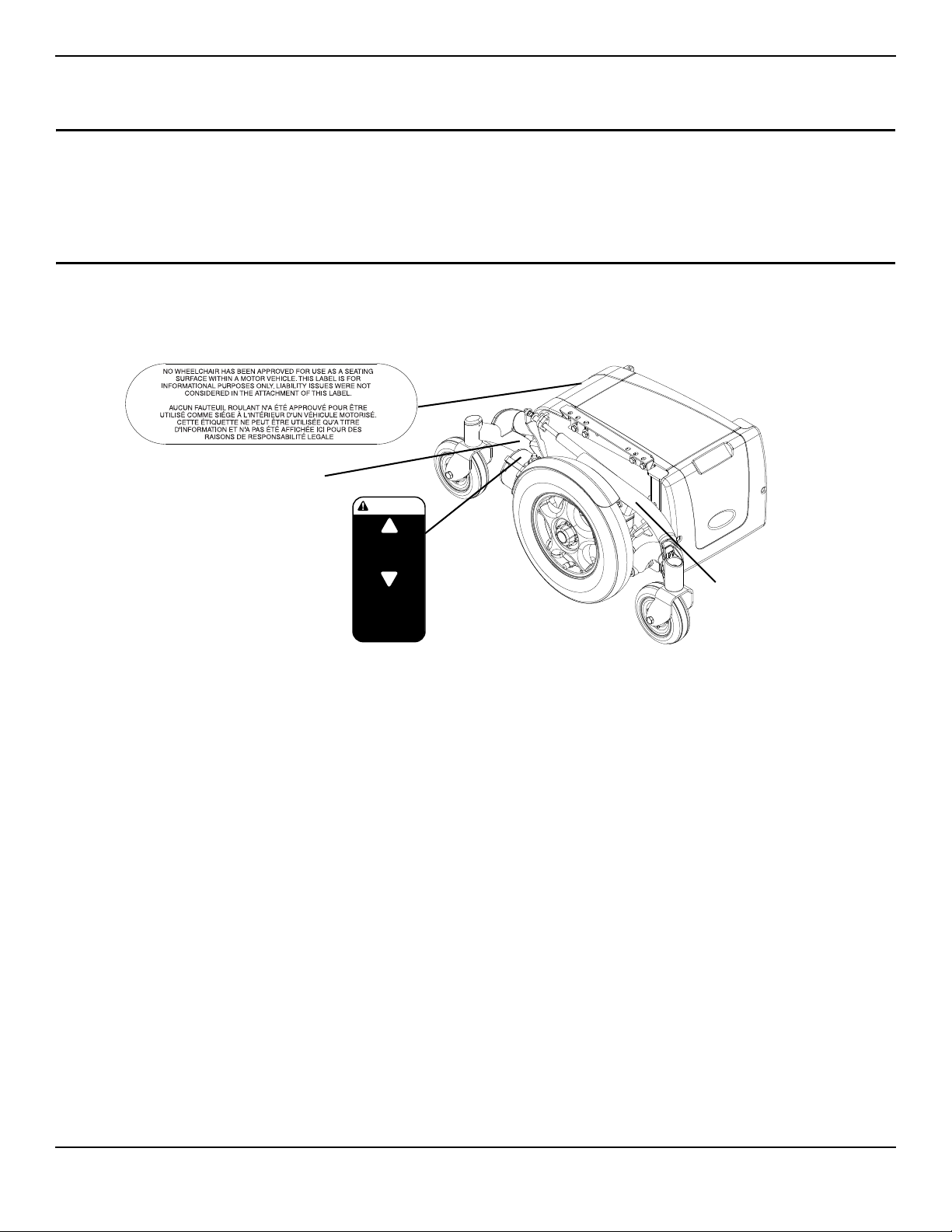
LABEL LOCATIONS
Serial Number Label is
located on the right side
rear swingarm.
Weight Capacity
Label located here
(Base Only)
P/N 1118367
Rev A - 3/03
DRIVE
PUSH
CAUTION
Ensure both clutches
are fully engaged
before driving chair
Located on each
4-pole motor
LABEL LOCATIONS
DANGER
Risk of Injury, Damage or Death
Missing or damaged labels may contribute to injury damage or death.
- Ensure labels are present and legible.
NOTE: Labels are subject to change without notice.
All Wheelchairs
TDX® SP 8 Part No 1143209
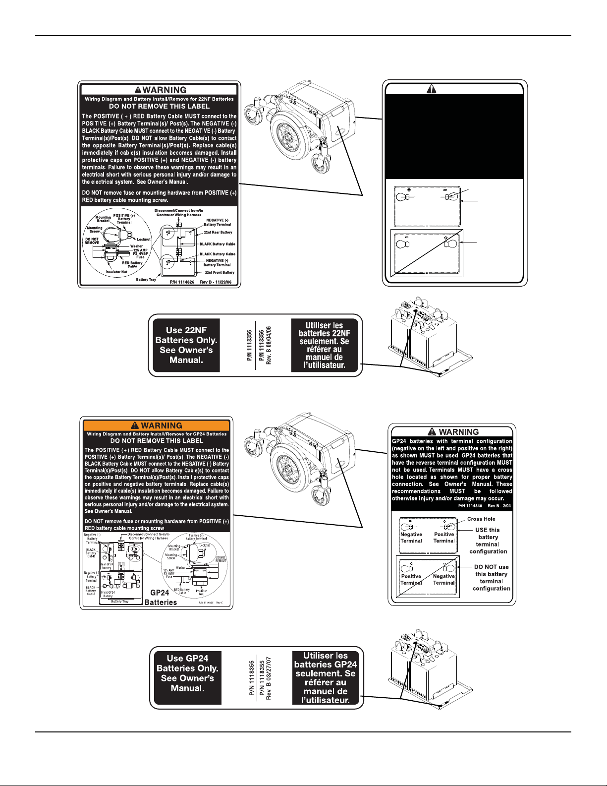
Wheelchairs with 22NF Batteries
WARNING
USE this
battery
terminal
configuration
Positive
Terminal
Negative
Terminal
Positive
Terminal
Negative
Terminal
P/N 1114847 Rev B - 2/04
Cross Hole
DO NOT use
this battery
terminal
configuration
22NF batteries with terminal configuration
(positive on the left and negative on the right)
as shown MUST be used. 22NF batteries that
have the reverse terminal configuration MUST
not be used. Terminals MUST have a cross
hole located as shown for proper battery
connection. See Owner's Manual. These
recommendations MUST be followed
otherwise injury and/or damage may occur.
LABEL LOCATIONS
Wheelchairs with GP24 Batteries
Part No 1143209 9 TDX® SP
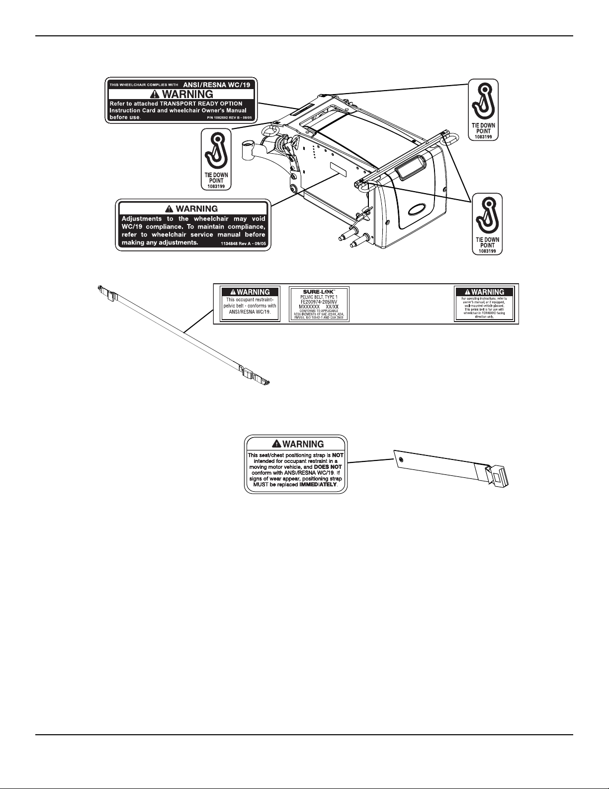
LABEL LOCATIONS
NOTE: Also on opposite side.
NOTE: Auto style seat positioning strap
shown. This label is also on the airline
style seat positioning strap.
Wheelchairs with TRRO
Wheelchairs without TRRO
TDX® SP 10 Part No 1143209

SPECIFICATIONS
SPECIFICATIONS
TDX SP
TDX SP
MODELS: TDXSPBASE, TDXSP, TDXSP-CG, TDXSP-MCG, TDXSP-CG-GT,
TDXSP-GT, TDXSP-MCG-GT
BASE LENGTH (WITHOUT FRONT RIGGINGS): 35.25 inches
OVERALL WIDTH OF BASE
(WITHOUT JOYSTICK): 24 inches (With two 22NF Batteries)
25.5 - inches (With two GP 24 Batteries or three 22NF Batteries)
OVERALL HEIGHT
WITH ASBA SEAT:
WITH FORMULA CG TILT ONLY:
OVERALL LENGTH
WITH CENTER MOUNT FRONT RIGGING:
WITHOUT FRONT RIGGINGS:
WEIGHT (BASE ONLY)
WITHOUT 22NF BATTERIES:
WITH TWO 22NF BATTERIES:
WITHOUT GP24 BATTERIES:
WITH TWO GP24 BATTERIES:
WITH TRANSPORT READY OPTION:
MOTOR: 4 Pole
35.5 to 39.5 inches
36.5 to 40.5 inches
42.9 inches @ 0°
35.25 inches
123 lbs
221 lbs
158 lbs
260 lbs
Add 10 lbs
DRIVE AXLE: Non-adjustable
*DRIVE WHEELS/TIRES: 14 x 3-inch Foam Filled or Pneumatic (Standard)
*CASTERS: 6 x 2-inch, Semi-pneumatic with Precision Sealed Bearings
CASTER FORKS: Two side fork
BATTERY REQUIREMENTS
NUMBER OF BATTERIES NEEDED:
MANUFACTURER:
MODEL:
VOLTAGE:
CAPACITY (AMP-HOURS) FOR 5 HOUR RATING:
NOTE: Only sealed non-spillable batteries that meet DOT
CFR 173.159 (d), IATA Packing Instructions 806, and IATA
Provision A67 shall be installed in this wheelchair.
OPERATING TEMPERATURE
STORAGE TEMPERATURE
FOOTRESTS: Telescoping Front Rigging Supports,
SEAT TILT ANGLE ADJUSTMENT: Adjustable (0° to 10°)
NOTE: All dimensions are ± .50 inches unless otherwise indicated.
*NOTE: The size of tire is marked on the side wall of each drive tire. The caster tires do not have the tire size marked as the caster tires
are not serviceable. If new tire is needed, the entire caster wheel assembly MUST be replaced.
p/n M24SLDG batteries only
GP24
2
MK batteries
p/n M22NFSLDG batteries only
12
63
122 F (50 C) Maximum to -13 F (-25 C) Minimum
149 F (65 C) Maximum to -58 F (-40 C) Minimum
2-inch and 4-inch long Pivot Slide Tube
MK batteries
22NF
2
12
43.2
Part No 1143209 11 TDX® SP

SPECIFICATIONS
TDX SP
WEIGHT LIMITATION
WITH ASBA SEAT:
WITH FORMULA™ CG POWERED SEATING:
4 POLE
Up to 300 lbs
Up to 300 lbs
WARNING
Risk of Death or Serious Injury
Exceeding the weight capacity of the wheelchair/seating system could cause instability resulting
in death or serious injury.
– DO NOT exceed the weight capacity.
NOTE: Weight limitation is total weight (user weight plus any additional items that the user may require [back pack, etc.]). Example:
If weight limitation of the wheelchair is 300 lbs and additional items equal 25 lbs, subtract 25 lbs from 300 lbs this means the maximum
weight limitation of the user is 275 lbs.
NOTE: All dimensions are ± .50 inches unless otherwise indicated.
*NOTE: The size of tire is marked on the side wall of each drive tire. The caster tires do not have the tire size marked as the caster tires
are not serviceable. If new tire is needed, the entire caster wheel assembly MUST be replaced.
TDX® SP 12 Part No 1143209

SECTION 1—GENERAL GUIDELINES
SECTION 1—GENERAL GUIDELINES
NOTE: SECTION 1 - GENERAL GUIDELINES contains important information for the safe operation and use of this product.
General
DANGER
Risk of Death, Serious Injury or Damage
Improper use of this product may cause injury or damage.
If you are unable to understand the warnings, cautions or instructions, contact a health care
professional or dealer before attempting to use this equipment.
- DO NOT use this product or any available optional equipment without first completely reading
and understanding these instructions and any additional instructional material such as user
manuals, service manuals or instruction sheets supplied with this product or optional equipment.
Continued use of the wheelchair with damaged parts could lead to the wheelchair malfunctioning
causing injury to the user and/or caregiver.
- Check all wheelchair components and carton for damage and test components before use. In
case of damage or if the wheelchair is not working properly, contact a qualified technician or
Invacare for repair.
Accessories
WARNING
Risk of Serious Injury or Damage
Use of non-Invacare accessories may result in serious injury or damage.
Invacare products are specifically designed and manufactured for use in conjunction with
Invacare accessories. Accessories designed by other manufacturers have not been tested by
Invacare and are not recommended for use with Invacare products.
DO NOT use non-Invacare accessories.
To obtain Invacare accessories, contact Invacare by phone or at www.invacare.com.
Replacement Parts
DANGER
Risk of Death, Serious Injury or Damage
Use of incorrect or improper replacement (service) parts may cause death, serious injury, or
damage.
Replacement parts MUST match original Invacare parts.
ALWAYS provide the wheelchair serial number to assist in ordering the correct replacement
parts.
Part No 1143209 13 TDX® SP

SECTION 1—GENERAL GUIDELINES
Repair or Service Information
DANGER
Risk of Death, Serious Injury, or Damage
Continued use of the wheelchair that is not set to the correct specifications may cause erratic
behavior of the wheelchair resulting in death, serious injury, or damage.
Performance adjustments should only be made by professionals of the healthcare field or persons
fully conversant with this process and the driver's capabilities.
After the wheelchair has been set up/adjusted, check to make sure that the wheelchair performs
to the specifications entered during the set up procedure. If the wheelchair does not perform to
specifications, turn the wheelchair Off immediately and reenter set up specifications. Contact
Invacare, if wheelchair still does not perform to correct specifications.
WARNING
Risk of Death, Serious Injury, or Damage
Missing attaching hardware could cause instability resulting in death, serious injury or damage.
Ensure all attaching hardware is present and tightened securely.
WARNING
Risk of Serious Injury or Damage
Attaching hardware that is loosely secured could cause loss of stability resulting in serious injury
or damage
After ANY adjustments, repair or service and before use, make sure that all attaching hardware
is tightened securely.
DANGER
Risk of Death or Serious Injury
Electric shock can cause death or serious injury
To avoid electric shock, inspect plug and cord for cuts and/or frayed wires. Replace cut cords or
frayed wires immediately.
DANGER
Risk of Death, Serious Injury, or Damage
Corroded electrical components due to water and/or liquid exposure, or incontinent users can
result in death, serious injury, or damage.
– Minimize exposure of electrical components to water and/or liquids. Electrical components
damaged by corrosion MUST be replaced immediately.
– Wheelchairs that are used by incontinent users and/or are frequently exposed to water/liquids
may require replacement of electrical components more frequently.
TDX® SP 14 Part No 1143209

SECTION 1—GENERAL GUIDELINES
WARNING
Risk of Injury, Damage or Death
Malfunctioning or damaged joystick may cause unintended/erratic movement resulting in injury,
damage or death.
– Ensure the joystick is securely connected to controller.
– DO NOT use if joystick does not spring back to the neutral position or becomes sticky or
sluggish.
– DO NOT use if joystick boot is torn or damaged.
– DO NOT use with a broken or missing joystick knob.
– If unintended/erratic movement occurs, stop using the wheelchair immediately and contact a
qualified technician.
– Ensure control knobs are secure before using the wheelchair. Stop using the wheelchair
immediately and contact a qualified technician if control knobs are not secure.
G-Trac
WARNING
Risk of Serious Injury or Damage
Improperly connecting the motor leads to the controller may cause injury or damage.
WHEELCHAIRS WITH G-TRAC: Crossing the motor leads (for example: connecting the left
motor lead into the right motor connector on the controller) may result in unintended
movement.
DO NOT cross the motor leads when connecting the motors to the controller - otherwise injury
or damage may occur.
Stability Lock
DANGER
Risk of Death or Serious Injury
Not performing periodic maintenance on stability lock could result in death or serious injury.
ALWAYS perform the periodic maintenance to the stability lock listed in the inspection
checklist of this manual.
Part No 1143209 15 TDX® SP

SECTION 1—GENERAL GUIDELINES
Sip n’ Puff (Pneumatic) Controls
WARNING!
Risk of Injury or Damage
Improper mounting or maintenance of the Sip n’ Puff control including the mouthpiece and
breath tube may cause injury or damage.
Water inside the Sip n’ Puff interface module may cause damage to the unit.
Excessive saliva residue in the mouthpiece/straw can reduce performance.
Blockages, a clogged saliva trap or air leaks in the system may cause Sip N’ Puff not to function
properly.
– Ensure moving parts of the wheelchair, including the operation of powered seating, DO NOT
pinch or damage the Sip n’ Puff tubing.
– Saliva trap MUST be installed to reduce risk of water or saliva entering the Sip n’ Puff interface
module.
– Occasionally flush the mouthpiece to remove saliva residue.
– The mouthpiece/straw MUST be completely dry before installation.
– If Sip n’ Puff does not function properly, inspect system for blockages, clogged saliva trap or air
leaks.
– As necessary, replace mouthpiece, breath tube and saliva trap.
NOTE: Contact your Invacare dealer/provider for more information about maintaining and troubleshooting the Sip n’ Puff system.
Operating Information
WARNING
Risk of Minor to Serious Injury
Pinch points can cause minor to serious injury.
Be mindful of potential pinch points and use caution when using this product.
TDX® SP 16 Part No 1143209

SECTION 1—GENERAL GUIDELINES
WARNING
Risk of Injury, Damage or Death
Loss of traction or stability on inclines/grades or ramps may cause injury, damage or death.
Lighter weight users may be at an increased risk. Surfaces that may be wet, icy, oily, slippery,
painted, treated wood, rotten wood, rusted metal or other similar surfaces or materials may also
increase risk.
– DO NOT use on inclines or ramps where surface is uncertain or compromised.
– DO NOT use on inclines greater than nine (9) degrees.
– DO NOT operate the seating system while the wheelchair is moving. Stop before operating
seating system.
– DO NOT operate the seating system while on an incline. Operation on an incline may result in
increased instability.
– To determine and establish your particular safety limits, practice use of this product on various
sloping surfaces in the presence of a qualified healthcare provider before attempting active use of
this wheelchair.
– DO NOT use on inclines where line of sight is impaired.
– Travel at a reduced, constant speed and DO NOT make sudden stops or direction changes.
Release the joystick and allow the wheelchair to come to a full stop before changing directions.
Traveling at high speeds reduces traction and increases stopping distance.
– DO NOT drive in an elevated position while on an incline.
– DO NOT leave elevating legrests in the fully extended position when proceeding down
inclines/grades.
– DO NOT leave an unoccupied wheelchair unattended on inclines or ramps.
Electrical
Grounding Instructions
WARNING
Power wheelchairs are equipped with three-prong (grounding) plugs for protection against
possible shock hazards. Where a two-prong wall receptacle is encountered, it is the personal
responsibility and obligation of the customer to contact a qualified electrician and have the
two-prong replaced with a properly grounded three-prong wall receptacle in accordance with
the National Electrical code. If you must use an extension cord, use only a three-wire extension
cord having the same or higher electrical rating as the device being connected. DO NOT, under
any circumstances, cut or remove the round grounding prong from any plug used with or for
Invacare products. In addition, Invacare has placed RED warning tags on some equipment. DO
NOT remove these tags.
Part No 1143209 17 TDX® SP

SECTION 1—GENERAL GUIDELINES
DANGER
Risk of Death, Injury or Damage
Shock hazards and risk of fire exist due to use of improper extension cord and/or use of three
prong adapters.
– To avoid injury or product damage, when using an extension cord, use only a UL approved
three wire extension cord having at least 16 AWG (American Wire Gauge) wire and the same or
higher electrical rating as the device being connected.
– DO NOT use three prong to two prong adapters.
TDX® SP 18 Part No 1143209

SECTION 2—ELECTROMAGNETIC COMPATIBILITY (EMC) INFORMATION
SECTION 2—ELECTROMAGNETIC COMPATIBILITY
(EMC) INFORMATION
WARNING
CAUTION: IT IS VERY IMPORTANT THAT YOU READ THIS INFORMATION REGARDING
THE POSSIBLE EFFECTS OF ELECTROMAGNETIC INTERFERENCE ON YOUR POWERED
WHEELCHAIR.
Electromagnetic Interference (EMI) From Radio Wave Sources
Powered wheelchairs and motorized scooters (in this text, both will be referred to as powered
wheelchairs) may be susceptible to electromagnetic interference (EMI), which is interfering
electromagnetic energy (EM) emitted from sources such as radio stations, TV stations, amateur
radio (HAM) transmitters, two way radios, and cellular phones. The interference (from radio
wave sources) can cause the powered wheelchair to release its brakes, move by itself, or move in
unintended directions. It can also permanently damage the powered wheelchair's control
system. The intensity of the interfering EM energy can be measured in volts per metre (V/m).
Each powered wheelchair can resist EMI up to a certain intensity. This is called its "immunity
level." The higher the immunity level, the greater the protection. At this time, current
technology is capable of achieving at least a 20 V/m immunity level, which would provide useful
protection from the more common sources of radiated EMI.
There are a number of sources of relatively intense electromagnetic fields in the everyday
environment. Some of these sources are obvious and easy to avoid. Others are not apparent and
exposure is unavoidable. However, we believe that by following the warnings listed below, your
risk to EMI will be minimized.
The sources of radiated EMI can be broadly classified into three types:
1) Hand-held Portable transceivers (transmitters-receivers with the antenna mounted directly
on the transmitting unit. Examples include: citizens band (CB) radios, "walkie talkie",
security, fire and police transceivers, cellular telephones, and other personal communication
devices).
NOTE: Some cellular telephones and similar devices transmit signals while they are ON, even when not
being used.
2) Medium-range mobile transceivers, such as those used in police cars, fire trucks, ambulances
and taxis. These usually have the antenna mounted on the outside of the vehicle; and
3) Long-range transmitters and transceivers, such as commercial broadcast transmitters (radio
and TV broadcast antenna towers) and amateur (HAM) radios.
NOTE: Other types of hand-held devices, such as cordless phones, laptop computers, AM/FM radios,
TV sets, CD players, cassette players, and small appliances, such as electric shavers and hair dryers, so
far as we know, are not likely to cause EMI problems to your powered wheelchair.
Part No 1143209 19 TDX® SP

SECTION 2—ELECTROMAGNETIC COMPATIBILITY (EMC) INFORMATION
WARNING
Powered Wheelchair Electromagnetic Interference (EMI)
Because EM energy rapidly becomes more intense as one moves closer to the transmitting
antenna (source), the EM fields from hand-held radio wave sources (transceivers) are of special
concern. It is possible to unintentionally bring high levels of EM energy very close to the powered
wheelchair's control system while using these devices. This can affect powered wheelchair
movement and braking. Therefore, the warnings listed below are recommended to prevent
possible interference with the control system of the powered wheelchair.
Electromagnetic interference (EMI) from sources such as radio and TV stations, amateur radio
(HAM) transmitters, two-way radios, and cellular phones can affect powered wheelchairs and
motorized scooters. Also, the electronics used in our powered wheelchair can generate a low
level of electromagnetic interference, which however will remain within the tolerances
permitted by law.
FOLLOWING THE WARNINGS LISTED BELOW SHOULD REDUCE THE CHANCE OF
UNINTENDED BRAKE RELEASE OR POWERED WHEELCHAIR MOVEMENT WHICH
COULD RESULT IN SERIOUS INJURY.
1) Do not operate hand-held transceivers (transmitters receivers), such as citizens band (CB)
radios, or turn ON personal communication devices, such as cellular phones, while the
powered wheelchair is turned ON;
2) Be aware of nearby transmitters, such as radio or TV stations, and try to avoid coming close
to them;
3) If unintended movement or brake release occurs, turn the powered wheelchair OFF as soon
as it is safe;
4) Be aware that adding accessories or components, or modifying the powered wheelchair, may
make it more susceptible to EMI (NOTE: There is no easy way to evaluate their effect on the
overall immunity of the powered wheelchair); and
5) Report all incidents of unintended movement or brake release to the powered wheelchair
manufacturer, and note whether there is a source of EMI nearby.
Important Information
1) 20 volts per metre (V/m) is a generally achievable and useful immunity level against EMI (as of
May 1994) (the higher the level, the greater the protection);
2) This device has been tested to a radiated immunity level of 20 volts per meter.
3) The immunity level of the product is unknown.
Modification of any kind to the electronics of this wheelchair as manufactured by Invacare may
adversely affect the EMI immunity levels.
CAUTION
Risk of Injury or Damage
EMC interference affecting other products may result in injury or damage.
To avoid impacting the operation and function of other products:
- Products not specified by Invacare that may be used on or near the wheelchair may be
impacted by emissions from this product if they have a sensitivity level that is lower than the
recognized standard and provided by this wheelchair. Refer to the manufacturer specifications
for any electronic device BEFORE use near this product to determine its level of immunity and
potential risk.
TDX® SP 20 Part No 1143209

SECTION 3—SAFETY INSPECTION/TROUBLESHOOTING
SECTION 3—SAFETY INSPECTION/TROUBLESHOOTING
Safety Inspection Checklists
NOTE: Initial adjustments should be made to suit the end user's personal body structure needs and preference. After initial setup, perform these
procedures every time the wheelchair is serviced.
Inspect/Adjust Initially
DANGER
Risk of Injury, Damage or Death
Overinflation of tires may cause tires to explode.
—Inflate tire to the proper tire pressure (P.S.I./ kilopascals) listed on the side wall of the tire.
—Only use wheelchair with tires at proper tire pressure.
—The wheels and tires should be checked periodically for cracks and wear and should be
replaced if necessary.
❑ Ensure wheelchair rolls straight (no excessive drag or pull to one side).
❑ Inspect all fasteners.
❑ Inspect TRRO/TRBKTS fasteners and hardware.
❑ Ensure clothing guards are secure.
❑ Arms are secure but easy to release and adjustment levers engage properly.
❑ Adjustable height arms operate and lock securely.
❑ Upholstery has no rips.
❑ Armrest pad sits flush against arm tube.
❑ Axle nut and wheel mounting nuts are secure on drive wheels.
❑ No excessive side movement or binding when drive wheels are lifted and spun when disengaged (free-wheeling).
❑ Ensure that casters are free of debris.
❑ Wheels/casters have proper tension when wheels/casters are spun (when free-wheeling). Wheels/casters should come to a
gradual stop.
❑ Loosen/tighten caster locknut if wheel wobbles noticeably or binds to a stop.
❑ Ensure all caster/wheel/fork/headtube fasteners are secure and not damaged/missing.
❑ Wheel locks DO NOT interfere with tires when rolling.
❑ Wheel lock pivot point are free of wear and looseness.
❑ Wheel locks are easy to engage.
❑ Inspect tires for flat spots and wear.
❑ Check pneumatic tires for proper inflation.
❑ Check center mount front riggings for worn/frayed belts and/or loose fasteners. If found, replace these items.
❑ Check that all labels are present and legible. Replace if necessary.
❑ Inspect locking gas cylinders.
❑ Clean upholstery and armrests.
❑ Clean dirt and lint from axles.
❑ Clean dirt and lint from bearings.
❑ Inspect mechanical anti-dive for function.
❑ Inspect seat positioning strap for any signs of wear. Ensure buckle latches. Verify hardware that attaches strap to frame is
secure and undamaged. Replace if necessary.
❑ Inspect foam handgrips for damage. If damaged, have them replaced by a qualified technician.
❑ Inspect motor brushes and gearbox coupling.
❑ Inspect electrical components for signs of corrosion. Replace if corroded or damaged.
❑ For optimum performance, replace locking-gas cylinders every two years.
Part No 1143209 21 TDX® SP

SECTION 3—SAFETY INSPECTION/TROUBLESHOOTING
Troubleshooting - Mechanical
SOLUTIONS
TURN/
SLUGGISH
WHEELCHAIR
VEERS LEFT/RIGHT
X X X If pneumatic, check tires for correct and equal pressure.
X X X X Check for loose stem nuts/bolts.
X X Check that casters contact ground at the same time.
CASTERS
FLUTTER
PERFORMANCE
SQUEAKS AND
RATTLES
LOOSENESS
IN WHEELCHAIR
X X If pneumatic, check tires for correct and equal pressure.
WHEELS
WHEELCHAIR 3
Troubleshooting - Electrical
NOTE: For additional troubleshooting information and explanation of error codes, refer to the individual Electronics Manual supplied with
each wheelchair.
SPJ™+, SPJ+ w/PSS or SPJ+ w/ACC Joysticks
The joystick information gauge and the service indicator give indications of the type of fault or error detected by the control
module. When a fault is detected, the wheelchair may stop and not drive. The LEDs on the information gauge may flash in a
particular pattern or the service indicator light will flash. The number or type of flashes indicates the nature of the error. If multiple
errors are found, only the first error encountered by the control module will be displayed.
TDX® SP 22 Part No 1143209
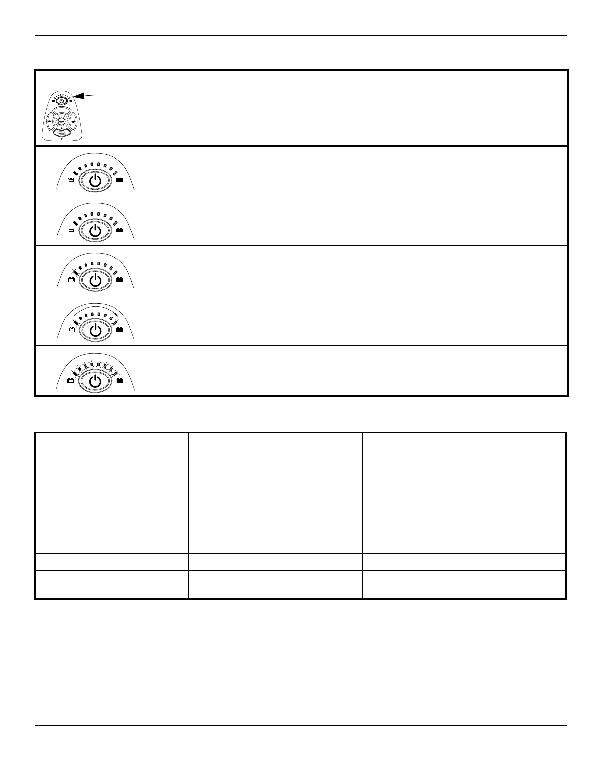
Information Gauge Display Diagnostics
Information
Gauge
Display
DISPLAY DESCRIPTION DEFINITION COMMENTS
All LEDs are off. Power is off.
All LEDs are on. Power is on. Fewer than three LEDs on implies
Left RED LED is flashing. Battery charge is low. The batteries should be charged
SECTION 3—SAFETY INSPECTION/TROUBLESHOOTING
reduced battery charge.
as soon as possible.
Left to Right “chase”
alternating with steady display.
All LEDs are flashing slowly. Joystick has detected Out- of-
Joystick is in programming,
inhibit and/or charging mode.
Neutral-at-Power-Up mode.
The steady LEDs indicate the
current state of the battery
charge.
Release the joystick to Neutral.
Service Indicator Light Diagnostics
POSSIBLE
ERROR CODE
DESCRIPTION
DIAGNOSTICS CODE
NUMBER OF FLASHES
1 E 01 User Fault 00 Stall Timeout or user error. Release joystick to neutral and try again.
2 E02 Battery Fault 00 Recharge batteries or replace. Check the batteries and cable. Try charging the
SUB CODE*
DETAILS OF
ERROR CODE
batteries. Batteries may require replacing.
SOLUTION
Part No 1143209 23 TDX® SP

SECTION 3—SAFETY INSPECTION/TROUBLESHOOTING
POSSIBLE
ERROR CODE
DESCRIPTION
DIAGNOSTICS CODE
NUMBER OF FLASHES
3 E03 Left Motor Fault 00 Left Motor Short Circuit Check the left motor, connections and motor
SUB CODE*
01 Left Motor Open Circuit
02 Left Motor Connection Fault B-
03 Motor Terminal Connected to B+
04 Left Motor Voltage Fault
05 Left Motor Bridge Fault
06 Too Many Hardware Current
07 Current Offset Out of Range
08 Hardware Current Limit Fault
DETAILS OF
ERROR CODE
Limit Events
cable.
SOLUTION
4 E04 Right Motor Fault 00 Right Motor Short Circuit Check the right motor, connections and motor
01 Right Motor Open Circuit
02 Right Motor Connection Fault B-
03 Motor Terminal Connected to B+
04 Right Motor Voltage Fault
05 Right Motor Bridge Fault
06 Too Many Hardware Current
Limit Events
07 Current Offset Out of Range
08 Hardware Current Limit Fault
5 E05 Left Park Brake Fault 00 Left Park Brake Drive-Time Test
Failed
01 Left Park Brake Output Enabled
When Wheelchair Idle
02 Left Park Brake Output Did not
Enable When Entering Drive Mode
03 Left Park Brake fault during
power-up testing
04 Left park brake feedback low
during drive (park brake short)
cable.
Check the left park brake connections and cable.
TDX® SP 24 Part No 1143209

SECTION 3—SAFETY INSPECTION/TROUBLESHOOTING
ERROR CODE
DESCRIPTION
DIAGNOSTICS CODE
NUMBER OF FLASHES
6 E06 Right Park Brake Fault 00 Right Park Brake Drive-Time Test
7 E07 Remote Fault 00 Local SR Fault (CPU, EEPROM,
SUB CODE*
01 Right Park Brake Output Enabled
When Wheelchair Idle
02 Right Park Brake Output Did not
Enable When Entering Drive Mode
03 Right Park Brake fault during
power-up testing
04 Right park brake feedback low dur-
ing drive (park brake short)
DETAILS OF
ERROR CODE
Failed
etc.)
POSSIBLE
SOLUTION
Check the right park brake connections and
cable.
Check the communications bus, connections and
wiring. Replace the remote.
01 Joystick fault at the remote
02 Speed pot fault at the remote
8 E08 Controller Fault 00 Controller fault Check connections and wiring. Replace power
01 RAM fault
02 ROM fault
03 CPU fault
04 EEPROM fault
05 Watchdog fault
06 Stack fault
07 Software fault
08 Power-up testing fault
09 Relay fault or precharge fault
10 Bridge fault or disable all fault
11 Electronics fault: Thermistor
12 Calibration setting fault
9 E09 Communications Fault 00 Remote connection lost Check connections and wiring. Replace Bus
01 Low communication mode
10 E10 General Fault 00 General fault Check all connections and wiring. Contact
11 E11 Incompatible/incor-
rect Remote
00 Incompatible/incorrect Remote Wrong type of remote connected. Ensure the
module.
cable.
Invacare Technical Service.
branding of the joystick matches that of
controller unit.
Part No 1143209 25 TDX® SP
SECTION 3—SAFETY INSPECTION/TROUBLESHOOTING
MPJ™+, PSR+, PSF+ Joysticks or Displays
SYMPTOM PROBABLE CAUSE SOLUTIONS
SPM L Park Brake Fault or
SPM R Park Brake Fault displays and
wheelchair does not drive.
CHARGER PLUGGED IN displays. Battery charger connected (Error
SPM Battery Fault displays and the
wheelchair does not drive.
JOYSTICK TIMEOUT displays and the
wheelchair does not drive.
JS REV TOO LARGE
JS FWD TOO LARGE
JS LFT TOO LARGE or
Motor lock levers disengaged (Error
code E9 or E10).
code E28).
Batteries need to be charged (Error
code E14).
Joystick or input device is
disconnected (Error code 32).
The joystick or input device is sending
a value outside of the reverse,
forward, left or right limits (Error
codes E01, E02, E03 or E04).
Engage motor lock levers. Refer to user
manual shipped with wheelchair.
Unplug battery charger from the wheelchair.
Refer to Charging Batteries
Charge batteries. Refer to Charging Batteries
on page 72. If batteries fail to charge properly,
check battery charger or replace batteries.
Refer to Replacing Batteries
Turn off power, reconnect the joystick of
input device and turn power on.
Replace joystick or input device.
JS RGT TOO LARGE
displays and the wheelchair does not drive.
NEUTRAL TESTING displays. The joystick neutral test has failed
(Error code E18).
BAD JOYSTICK CAL VALUES displays
and the wheelchair does not drive.
SPM NOT CONNECTED
SPM Communications Fault displays and
the wheelchair drives slowly.
ATTENDANT ACTIVE and displays.
Batteries draw excessive current when
charging.
Battery indicator flashes the charge level is
low - immediately after recharge.
Battery indicator flashes the charge level is
low - too soon after being recharged.
Motor “chatters” or runs irregular. Electrical malfunction. Contact Invacare for service.
The joystick calibration values are
outside of the expected range (Error
code E19).
The MPJ or Display module is not
communicating with the control
module (Error code E200).
The controller has determined a fault
during a previous turn-off process
(Error code E41).
The Proportional or Digital Attendant
control is active and can be used to
drive the chair (Error code W05).
Battery failure.
Electrical malfunction.
Battery failure.
Malfunctioning battery charger.
Electrical malfunction.
Batteries not charged.
Weak batteries.
Release the joystick and try to get the joystick
back into the center-most position.
Recalibrate the joystick (joystick throw
procedure).
Check the connections between the joystick
or display and the controller. Turn the power
off and then back on. Replace the controller if
necessary.
Turn the wheelchair off and back on.
This is normal behavior.
Have batteries checked for shorted cell.
Replace if necessary. Refer to Replacing
Batteries on page 65.
Contact Invacare for service.
Check batteries for shorted cell. Replace if
necessary.
Replace charger.
Contact Invacare for service.
Have charger checked.
Replace batteries if necessary. Refer to
Replacing Batteries
on page 65.
on page 72.
on page 65.
TDX® SP 26 Part No 1143209

SECTION 3—SAFETY INSPECTION/TROUBLESHOOTING
SYMPTOM PROBABLE CAUSE SOLUTIONS
Joystick erratic or does not respond as
desired.
Wheelchair does not respond to
commands.
Power indicator off - even after recharging. Electrical malfunction. Contact Invacare for service.
Damaged motor coupling.
Electrical malfunction.
Controller programmed improperly.
Joystick error. Calibrate joystick.
Inspect motor coupling. Refer to Replacing the
SSD Motor or Gearbox Only on page 40.
Contact Invacare for service.
Check programming. See electronics manual.
Check programming.
Check "INPUT TYPE": Programming Menu.
Check joystick throw: DIAGNOSTICS menu.
Re-Calibrate Joystick.
Check Drive Lock Out status.
Check motor brake engagement.
Try different Joystick.
Troubleshooting - Motor/Gearbox/Brake
SYMPTOM PROBABLE CAUSE SOLUTIONS
Motor makes a clicking noise.
Grinding noise or motor is locking up.
Motors stall and starts up again.
Wheelchair will not drive with power on
(E09 or E10).
Motor chatters or runs erratically, or only
one motor turns.
Bad gearbox, chipped or worn
gears.
bad bearings.
Raised commutator plate inside of
motor.
Bad gearbox.
Bad coupler between motor and
gearbox or bad bearings. Bad Gears.
Current Rollback. Stop driving the wheelchair and , with the
Check motor locks. Engage motor locks to drive wheelchair.
Damaged connector or worn
brushes.
Bad motor or gear box.
Commutator bars expanded.
Water or oil in motor.
Replace gearbox.
If bearings are bad, replace motor.
Ohm out motor and replace motor if high
reading is present. Normal reading is .5-5
Ohms.
Replace gearbox.
Replace coupler.
If bearings are bad, replace motor.
power on, let electronics cool.
Swap out motor leads. Using a programmer,
check for error codes.
NOTE: WHEELCHAIRS WITH G-TRAC
ONLY - Before swapping motor leads for
troubleshooting purposes, use the
programmer to turn off G-trac in all drives.
Ohm out motors. Check brushes and
replace brushes if necessary. Replace motor
if high reading is present. Normal reading is
.5-5 Ohms. 4 Pole ONLY.
Inspect commutator bars for expansion
from getting to hot. Replace motor.
Rotate gearbox by hand.
Controller malfunction. Check for error codes with programmer.
Refer to the MK6i Electronics Programming
Guide, part number 1141471.
Part No 1143209 27 TDX® SP
 Loading...