

Invacare TDX SP2, TDX SP2 Series Service Manual
Invacare®TDX®SP2Series
enPowerWheelchair
ServiceManual
DEALER:Keepthismanual.
TheproceduresinthismanualMUSTbeperformedbyaqualied
technician.

©2017InvacareCorporation
Allrightsreserved.Republication,duplicationormodicationinwholeorinpartisprohibitedwithoutpriorwritten
permissionfromInvacare.Trademarksareidentiedby™and®.AlltrademarksareownedbyorlicensedtoInvacare
Corporationoritssubsidiariesunlessotherwisenoted.
Invacarereservestherighttoalterproductspecicationswithoutfurthernotice.

Contents
1General.........................................4
1.1Aboutthismanual..............................4
1.2Generalinformation............................4
1.3Notesonshipping..............................4
1.4Symbolsinthismanual..........................4
1.5Imagesinthismanual...........................4
2Safety..........................................5
2.1Safetyandttinginstructions.....................5
3Hygiene.........................................7
3.1Handlingofreturnedusedproducts.................7
4Setup...........................................8
4.1Adjustingseatingposition........................8
4.1.1Adjustinglowerleglength.....................8
4.1.2Adjustingseatdepth.........................8
4.1.3Adjustingcenterofgravityofseat...............8
4.1.4Moduliteseat..............................9
5T esting..........................................11
5.1Testingmotor.................................11
5.2Testingmotorbrake............................11
5.3Raintest.....................................11
5.4Fieldloadtest.................................11
5.5CheckingBatteryChargeLevel.....................12
6Service..........................................13
6.1Tighteningtorques.............................13
6.2Overviewmobilitydevice.........................13
6.3Chassis......................................14
6.3.1Stabilitylock...............................14
6.3.2WalkingBeams.............................17
6.3.3Steeringheadfront..........................18
6.3.4Removingrearsprings.......................18
6.3.5Installingrearsprings.........................18
6.3.6Replacingbatterytray........................19
6.3.7Replacingbatterybox.........................19
6.3.8Replacingrubberstopper......................20
6.4Drivecomponents..............................20
6.4.1Overviewmotor.............................20
6.4.2Replacingmotor/gearboxunit...................21
6.4.3Replacingorrotatingmotor/gearboxunitsealing
ring.....................................21
6.4.4Replacingmotor/gearboxclutch.................22
6.4.5Replacingcarbonbrushes......................22
6.4.6Replacingdrivewheelhub.....................23
6.4.7Replacingmotor/gearboxunit...................23
6.5Wheels......................................24
6.5.1Replacingriminsertsindrivewheels.............24
6.5.2Replacingcasterfork.........................24
6.5.3Adjustingcasterfork.........................25
6.5.4Replacingcastersondouble-sidedcasterforks......25
6.5.5Replacingcastersonsingle-sidedcasterforks.......26
6.5.6Replacingdrivewheel........................26
6.5.7Replacingtireorinnertube....................26
6.5.8Removingrearsuspension.....................28
6.5.9Removingrearsuspension–alternativemethod.....28
6.5.10Rettingrearsuspension.....................29
6.5.11Rettingrearsuspension–alternativemethod.....29
6.6Shrouds.....................................30
6.6.1Removingfrontshroud........................30
6.6.2Removingrearshroud........................30
6.6.3Removingtopshroud.........................30
6.6.4Replacingmudguard.........................31
6.7Controls.....................................31
6.7.1Replacingpowermodule......................31
6.7.2ReplacingG-Tracsensor.......................31
6.7.3Replacingoperatinghourcounter/connecting
cable....................................31
6.7.4Updatingdrivingprogram......................32
6.7.5Makingbatteriesaccessible....................32
6.7.6Replacingbatteries...........................33
6.7.7Removingthebatteries.......................34
6.7.8Replacingbatteries(Poweredsimpletilt20°).......34
6.7.9Replacingbatteries/replacingbatterycables........35
6.7.10Removingthebatteries......................36
6.7.11Generalinstructionsonhandlingthebatteries.....36
6.7.12Howtohandledamagedbatteriescorrectly.......37
6.7.13Checkingandreplacingmainfuse...............37
6.7.14ReplacingUSBcharger.......................38
6.7.15Checkingcable.............................38
6.7.16Cablerouting..............................38
6.8Lightingunit..................................38
6.8.1Replacingfrontbulb(conventionallighting
system)..................................38
6.8.2Replacingheadlightcomplete(conventionallighting
system)..................................39
6.8.3Replacingheadlightcomplete(LEDlighting
system)..................................39
6.8.4Replacingfrontlampholder(conventionallighting
system)..................................39
6.8.5Replacingfrontlampholder-(conventionallighting
system)..................................40
6.8.6Replacingfrontlampholder-(LEDlighting
system)..................................40
6.8.7Replacingrearbulb(conventionallighting
system)..................................40
6.8.8Replacingrearlightcomplete-(conventional
lightingsystem)............................40
6.8.9Replacingcompleterearlight-(LEDlighting
system)..................................41
6.8.10Replacingrearlampholder-(conventionallighting
system)..................................41
6.9Seating......................................41
7Troubleshooting...................................42
7.1Operationalfaults..............................42
7.2Drivefaultdiagnosis............................42
7.3Chargerfaultdiagnosis..........................45
7.4Serviceplan(1xannually)........................46
8Accessories......................................49
8.1Accessorieslist................................49
Invacare®TDX®SP2Series
1General
1.1Aboutthismanual
•ThismanualreferstocongurationswithModuliteseat
system.Olderspecicationshavebeendescribedin
revision11ofthisservicemanual.
•Forseatsystems,refertothecorrespondingmanual.
•ForShark,DX,DX2,refertorevision11ofthisservice
manual.
•ForLiNXcontrols,refertoLiNXServiceManual.
1.2Generalinformation
•Serviceandmaintenanceworkmustbecarriedout
takingthisservicemanualintoaccount.
•Itisimperativethatyouobservesafetyinformation.
•Informationaboutoperationoraboutgeneral
maintenanceandcareworkonthemobilitydevice
shouldbetakenfromServicemanual.
•Y oucanndinformationaboutorderingsparepartsin
thesparepartscatalogue.
•SparepartsMUSTmatchoriginalInvacareparts.Only
usesparepartswhichhavebeenapprovedbyInvacare.
•Wereservetherighttomakeanyalterationsonthe
groundsoftechnicalimprovements.
•Formoreinformationabouttheproduct,forexample
productsafetynoticesandproductrecalls,contactyour
localInvacarerepresentative.Foraddressandwebsite
seebackpageofthismanual.
•Themobilitydevicemayonlybemaintainedand
overhauledbyqualiedpersonnel.
•Theminimumrequirementforservicetechniciansis
suitabletraining,suchasinthecycleororthopedic
mechanicselds,orsufcientlylong-termjob
experience.
–Experienceintheuseofelectricalmeasuring
equipment(multimeters)isalsoarequirement.
–SpecialInvacaretrainingisrecommended.
•Alterationstothemobilitydevicewhichoccurasaresult
ofincorrectlyorimproperlyexecutedmaintenanceor
overhaulworkleadtotheexclusionofallliabilityon
thesideofINVACARE.
•IfyouhaveanyproblemsorquestionscontactInvacare
Service.
1.3Notesonshipping
•Ifthemobilitydevicehastobeshippedbacktothe
manufacturerformajorrepairs,youshouldalwaysuse
theoriginalpackagingfortransport.
•Pleaseattachaprecisedescriptionofthefault.
1.4Symbolsinthismanual
Inthismanual,hazardstatementsareindicatedbysymbols.
Thesymbolsareaccompaniedbyasignalwordthatindicates
theseverityoftherisk.
WARNING
Indicatesahazardoussituationthatcouldresult
inseriousinjuryordeathifitisnotavoided.
CAUTION
Indicatesahazardoussituationthatcouldresult
inminororslightinjuryifitisnotavoided.
IMPORTANT
Indicatesahazardoussituationthatcouldresult
indamagetopropertyifitisnotavoided.
Givesusefultips,recommendationsand
informationforefcient,trouble-freeuse.
ThisproductcomplieswithDirective93/42/EEC
concerningmedicaldevices.Thelaunchdate
ofthisproductisstatedintheCEdeclaration
ofconformity.
Thissymbolidentiesalistofvarioustools,
componentsanditemswhichyouwillneedin
ordertocarryoutcertainwork.
1.5Imagesinthismanual
Thedetailedimagesinthismanualaregivenmarksto
identifyvariouscomponents.Componentmarksintextand
operationalinstructionsalwaysrelatetotheimagedirectly
above.
4
1532486-L

Safety
2Safety
2.1Safetyandttinginstructions
Thesesafetyinstructionsareintendedtopreventaccidents
atwork,anditisimperativethattheyareobserved.
Beforeanyinspectionorrepairwork
•Readandobservethisrepairmanualandtheassociated
usermanual.
•Observetheminimumrequirementsforcarryingoutthe
work(see1.2Generalinformation,page4).
Personalsafetyequipment
Safetyshoes
Themobilitydevice,andsomeofitscomponents,arevery
heavy.Thesepartscanresultininjuriestothefeetifthey
areallowedtodrop.
•Wearstandardizedsafetyshoesduringallwork.
Eyeprotection
Itispossiblethatbatteryacidcanbedischargedwhen
workingondefectivebatteriesorwhenhandlingbatteries
improperly.
•Alwaysweareyeprotectionwhenworkingonany
defectiveorpossiblydefectivebatteries.
Safetygloves
Itispossiblethatbatteryacidcanbedischargedwhen
workingondefectivebatteriesorwhenhandlingbatteries
improperly.
•Alwayswearacid-proofsafetygloveswhenworkingon
anydefectiveorpossiblydefectivebatteries.
Generalsafetyinformationandinformationabouttting
/removal
DANGER!
RiskofDeath,SeriousInjury ,orDamage
Lightedcigarettesdroppedontoanupholstered
seatingsystemcancauseareresultingin
death,seriousinjury,ordamage.Mobilitydevice
occupantsareatparticularriskofdeathor
seriousinjuryfromtheseresandresultingfumes
becausetheymaynothavetheabilitytomove
awayfromthemobilitydevice.
–DONOTsmokewhileusingthismobilitydevice.
WARNING!
RiskofSeriousInjuryorDamage
Storingorusingthemobilitydevicenearopen
ameorcombustibleproductscanresultin
seriousinjuryordamage.
–Avoidstoringorusingthemobilitydevicenear
openameorcombustibleproducts.
CAUTION!
Riskofcrushing
Variouscomponentssuchasthedriveunit,
batteries,seatetcareveryheavy.Thisresultsin
injuryhazardstoyourhands.
–Notethehighweightofsomecomponents.
Thisappliesespeciallytotheremovalofdrive
units,batteriesandtheseat.
CAUTION!
Injuryhazardifthevehiclestartsmoving
unintentionallyduringrepairwork
–Switchthepowersupplyoff(ON/OFFkey).
–Engagethedrive.
–Beforeliftingup,securethevehiclebyusing
chockstoblockthewheels.
CAUTION!
Fireandburnhazardduetoelectricalshort-circuit
–Themobilitydevicemustbecompletely
switchedoffbeforeremovalofvoltage-carrying
components!T odothis,removethebatteries.
–Avoidshort-circuitingthecontactswhen
carryingoutmeasurementsonvoltage-carrying
components.
CAUTION!
Riskofburnsfromhotsurfacesonthemotor
–Allowthemotorstocooldownbefore
commencingworkonthem.
CAUTION!
Injuryhazardandriskofdamagetovehicledue
toimproperorincompletemaintenancework
–Useonlyundamagedtoolsingoodcondition.
–Somemovingpartsaremountedinsockets
withPTFEcoating(T eon™).Nevergrease
thesesockets!
–Neveruse"normal"nutsinsteadofself-locking
nuts.
–Alwaysusecorrectly-dimensionedwashersand
spacers.
–Whenreassembling,alwaysreplaceanycable
tieswhichwerecutduringdismantling.
–Aftercompletingyourwork/beforerenewed
start-upofthemobilitydevice,checkall
connectionsfortighttting.
–Aftercompletingyourwork/beforerenewed
start-upofthemobilitydevice,checkallparts
forcorrectlocking.
–Onlyoperatethevehiclewiththeapprovedtire
pressures(seetechnicaldata).
–Checkallelectricalcomponentsforcorrect
function.Notethatincorrectpolaritycanresult
indamagetotheelectronics.
–Alwayscarryoutatrialrunattheendofyour
work.
CAUTION!
Riskofinjuryanddamagetoproperty ,ifthe
maximumspeedreductiononawheelchairwith
alifterdoesnotfunctioncorrectly
Thewheelchair’scontrolunitmustreducethe
maximumpossiblespeedassoonasthelifteris
raised.
–T estthemaximumspeedreductionforcorrect
functionafteranymaintenanceworkor
modicationstothewheelchair .
1532486-L5

Invacare®TDX®SP2Series
CAUTION!
Anychangestothedriveprogramcanaffectthe
drivingcharacteristicsandthetippingstability
ofthevehicle
–Changestothedriveprogrammayonlybe
carriedoutbytrainedInvacarespecialist
dealers.
–Invacaresuppliesallmobilitydeviceswitha
standarddriveprogramex-works.Invacarecan
onlygiveawarrantyforsafevehicledriving
behavior-especiallytippingstability-forthis
standarddriveprogram.
Markallcurrentsettingsforthemobilitydevice
(seat,armrests,backrestetc.),andtheassociated
cableconnectingplugs,beforedismantling.This
makesreassemblyeasier .Allplugsarettedwith
mechanicalsafetydeviceswhichpreventreleaseof
theconnectingplugsduringoperation.T oreleasethe
connectingplugsthesafetydevicesmustbepressed
in.Whenreassemblingensurethatthesesafety
devicesarecorrectlyengaged.
61532486-L

3Hygiene
3.1Handlingofreturnedusedproducts
Whenreconditioningorrepairingreturnedmobilitydevices:
•T akeprecautionsforyourselfandtheproduct.
•Useprotectionequipmentasspeciedlocally.
Beforetransport(accordingtoBiologicalAgentsOrdinance)
Treatproductaccordingtofollowingprocesssteps:
Hygiene
Processstep
Component
ApplicationConditioningtechniqueWorkstation
ManualcleaningSurfaceofuseddeviceBeforerepairor
reconditioning
DisinfectionSurfaceofuseddeviceBeforerepairor
reconditioning
*Invacareusesdetergent"Nücoseptspecial"1.5%inwaterml/ml
Disinfectiontools
•Onewaywipes(eece)
•Brushestocleandifculttoaccessareas
Furtherinformation
FormoreinformationcontactyourInvacareServicedepartment.
Usesaturatedtowel
toapplycleaning
detergentandremove
residuesafterimpact.
Usesaturated
disinfectantwipes
andclean*thedevice
surface.
Cleaningand
disinfection
Cleaningand
disinfection
1532486-L
7
Invacare®TDX®SP2Series
4Setup
4.1Adjustingseatingposition
Adjustingtheseatingpositioninordertoadaptthemobility
deviceoptimallytotherequirementsoftheuser,we
recommendthatyouaskyourauthorisedInvacare®dealer
toadjustseatdepthindividually .Adaptingtheseattothe
user'sseatingpositiondependsontheseatthathasbeen
tted,andshouldbecarriedoutinthefollowingsequence.
1.Adjustingthelowerleglengthandseatdepth.See
chapter4.1.1Adjustinglowerleglength,page8.
2.Adjustingthecenterofgravityoftheseatframe.See
chapter4.1.3Adjustingcenterofgravityofseat,page8.
3.Checkingthattheswivelcastorscanmovefreely.
4.Repetitionofsteps2to4,ifnecessary.
WARNING!
Riskofinjuryaftertiltingofmobilitycaused
byblockedsteeringwheels
–Alwayschecktheseatdepthsettingsfor
bothforwardandreversemovement.Make
surethatsteeringwheelscanrotatefreely
andhavenotcontacttoanyxedmobility
devicecomponent.
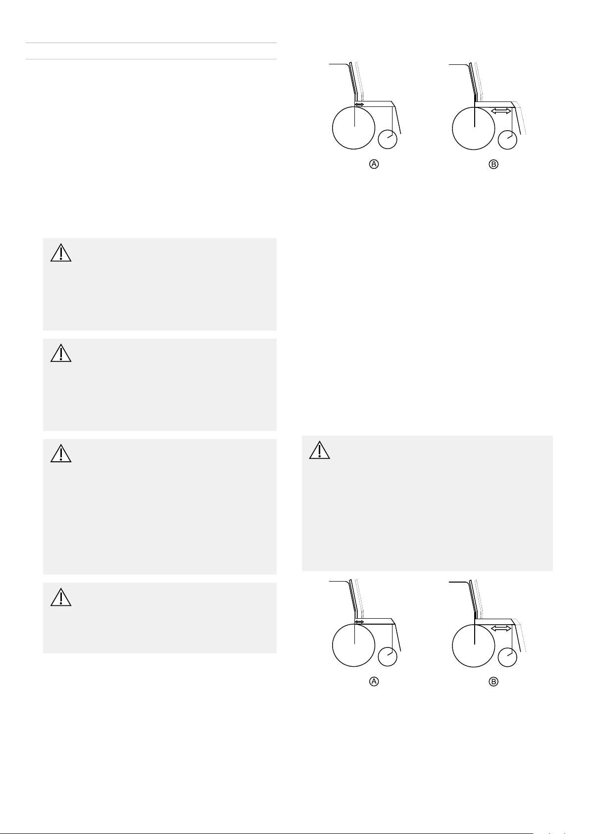
B:Centerofgravityoftheseat/seatposition
SeatdepthAcanbeadjustedbymovingbackrestinrelation
toseatsurface.
Moduliteseat
Theseatdepthisadjustedbyshiftingthepositionofthe
backrest.SeeUserManual.
Seatsystems
Fordetailson
•Standardseat
•Flexseat
•Contourseat
•Maxseat
CAUTION!
Riskoftippingover
Anychangeintheseatingpositioncan
negativelyinuencethestabilityofthe
mobilitydevice.
–Alwaysmakesurethatthemobilitydevice
isstableandwillnottipover,after
adjustingseatingposition.
WARNING!
Anychangestothedriveprogramcanaffect
thedrivingcharacteristicsandthetipping
stabilityofthemobilitydevice
–Changestothedriveprogrammayonlybe
carriedoutbytrainedInvacare®providers.
–Invacare®suppliesallmobilitydevices
withastandarddriveprogramex-works.
Invacare®canonlygiveawarrantyforsafe
vehicledrivingbehavior-especiallythe
tippingstability-forthisstandarddrive
program.
WARNING!
Riskofcrushing
Theseatisveryheavy.Riskofinjurytohands
andfeet.
–Payattentiontothehandandfeet.
–Useproperliftingtechniques.
refertorevision11ofthisservicemanual.
FordetailsonModuliteseatseebelow.
4.1.3Adjustingcenterofgravityofseat
Thecenterofgravityofseat(CoG)canbeadjustedby
mountingseatframefarthertowardsfrontortherearof
seat.
CAUTION!
Theseatingsystemofthemobilitydeviceis
deliveredexworkswithastandardadjustment
ofcenterofgravity(CoG),whichmeets80–90%
ofuserrequirements.CoGcanbeadjusted
individually.However,anychangeinthis
adjustmentsettingcannegativelyinuencethe
stabilityofthepowerwheelchair.
–Youmustperformanindividualriskanalysis
everytimeyouchangethecenterofgravity
oftheseatingposition,inordertoensurethe
safetyandstabilityofthepowerwheelchair.
4.1.1Adjustinglowerleglength
Invacareoffersarangeoflegrestswhichcanbeadjusted
individually.Seeusermanual.
4.1.2Adjustingseatdepth
A:Seatdepth
B:Centerofgravityoftheseat/seatposition
A:Seatdepth
81532486-L
Setup
Theuserweightandseatdepthhavestrong
inuencesonthechoiceofthecenterofgravity
(CoG).Iftheuserisheavyandtheseatdepthis
greater ,thefocusshouldbethefartherback.For
bestpossibledrivingcharacteristicsofrear-wheel
drivewheelchairs,theweightshouldbedistributed:
30–40%frontand60-70%rear.Forcenterwheel
drivestheweightshouldbedistributed25%front,
50%centerand25%rear.
CAUTION!
Riskofdamageduetocollisionsofthelegrests
withotherpartsofthemobilitydevice
–Setthelegreststothesmallestanglebefore
adjustingtheseatcenterofgravity.
–Payattentionwithadjustingseatcenterof
gravitythatlegrestsdonottouchanyother
partsofwheelchair .Thisensuresthatthe
legrestscannotcollidewithotherpartsof
wheelchair.
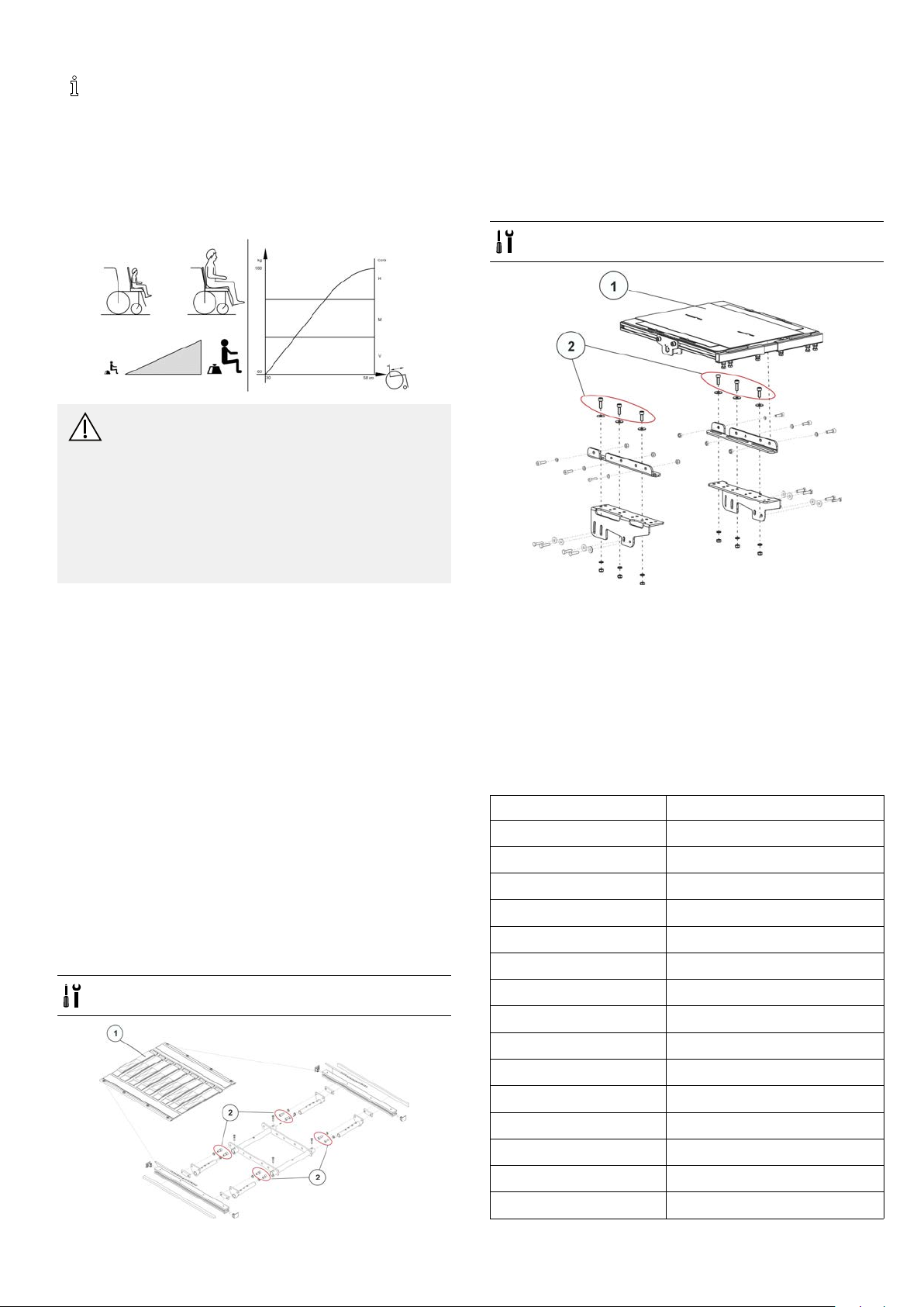
1.Removeseatplateorslingseat(1),seechapter
“Adjustingseatwidth”inModuliteservicemanual.
2.LoosenAllenscrews(2)infrontandrear,leftandright
–DONOTremove.
3.Shiftpositionofseat.
4.Tightenscrews.
5.Installseatplateorslingseat.
Onepieceseatplate(TDXSP2/TDXSP2NB)
•6mmAllenkey
Seatsystems
Fordetailson
•Standardseat
•Flexseat
•Contourseat
•Maxseat
refertorevision11ofthisservicemanual.
FordetailsonModuliteseatseebelow.
4.1.4Moduliteseat
TheModuliteseatisavailableintwoversions:
•T elescopicseatframe(plateandstrap):Adjustmentof
centerofgravityviathelateralproles,asdescribed
belowin“Telescopicseatframe”.
•Onepieceseatplate:Adjustmentofcenterofgravity
viatheoblongholesoftheseatadapterasdescribed
belowinchapter“Onepieceseatplate”.
Telescopicseatframe
•6mmAllenkey
1.Removeseatplate(1)orslingseat.Seechapter
“Adjustingseatwidth”inModuliteservicemanual.
2.LoosenAllenscrews(2)and(3)infrontandrear ,left
andright–DONOTremove.
3.Shiftpositionofseatframe.
4.Tightenscrews.
5.Installseatplate.
Imperialtometricconversionchart
Youcanusethischartasanorientationtondtheright
toolsize.
IMPERIALMETRIC
inch
5/64
3/32
7/64
1/8
9/64
5/32
11/64
3/16
13/64
7/32
15/64
1/4
17/64
9/32
mm
1.9844
2.3813
2.7781
3.1750
3.5719
3.9688
4.3656
4.7625
5.1594
5.5563
5.9531
6.3500
6.7469
7.1438
1532486-L9

Invacare®TDX®SP2Series
IMPERIALMETRIC
inch
19/64
5/16
21/64
11/32
23/64
3/8
25/64
13/32
27/64
7/16
29/64
15/32
31/64
1/2
33/64
17/32
35/64
9/16
37/64
IMPERIALMETRIC
mm
7.5406
7.9375
8.3344
8.7313
9.1281
9.5250
9.9219
10.3188
10.7156
11.1125
11.5094
11.9063
12.3031
12.7000
13.0969
13.4938
13.8906
14.2875
14.6844
inch
19/32
39/64
5/8
41/64
21/32
43/64
11/16
45/64
23/32
47/64
3/4
49/64
25/32
51/64
13/16
53/64
27/32
55/64
7/8
mm
15.0813
15.4781
15.8750
16.2719
16.6688
17.0656
17.4625
17.8594
18.2563
18.6531
19.0500
19.4469
19.8438
20.2406
20.6375
21.0344
21.4313
21.8281
22.2250
101532486-L
Testing
5Testing
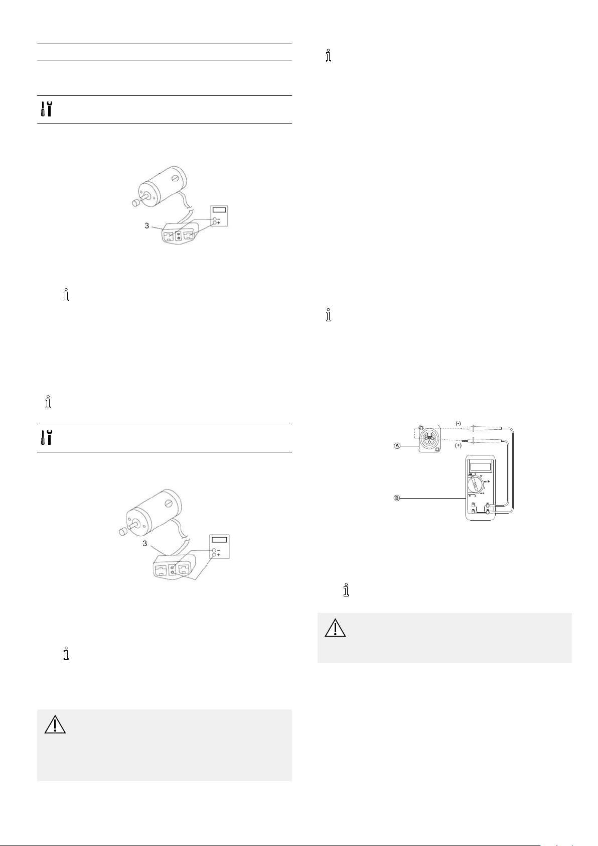
5.1Testingmotor
•Phillipsscrewdriversize2
•Digitalmultimeterwithresistancemeasurement
1.Removerearshroudasdescribedin6.6.2Removingrear
shroud,page30.
2.
Disconnectmotorplug(3)frompowermodule.
3.Connectdigitalmultimetertomotorplugcontacts(3)
andmeasureresistancebetweencontacts.
Aresistanceofbetween0.5and5ohmsindicates
amotorreadyforoperation.Aresistance
ofbetween15ohmsandinnityindicatesa
defectivemotor .Highresistancesarenormally
causedbybadconnectionsorworncarbon
brushes.
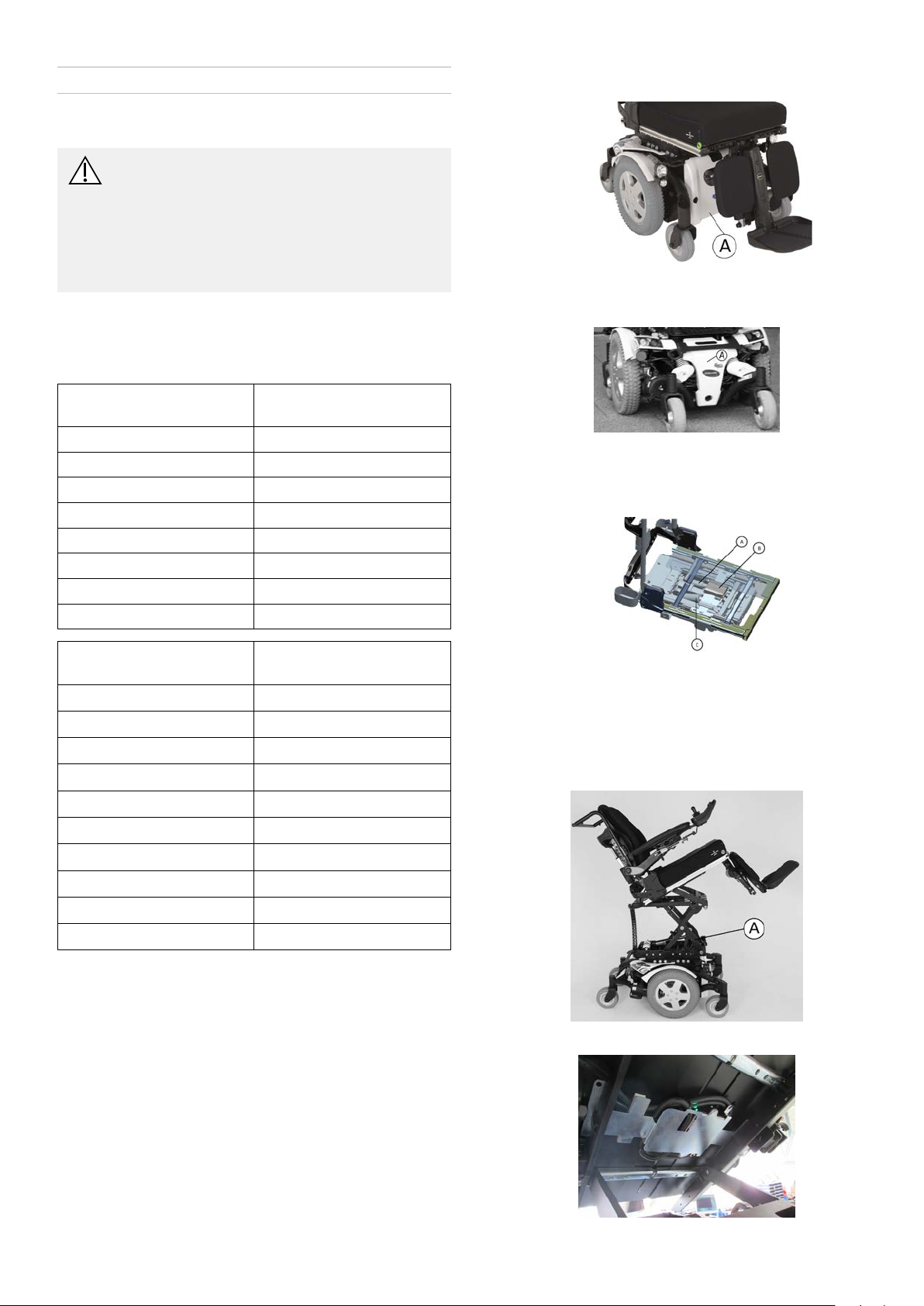
5.2Testingmotorbrake
Thistestshouldonlybecarriedoutonmobility
devicewithconventionalmotor/gearboxunits.
Adefectivemotorcandamagethepowermodule,
butnottheotherwayaround.
5.3Raintest
•Checktoensurethattheblackbatteryterminalcaps
aresecuredinplace,joystickbootisnottornor
crackedwherewatercanenterandthatallelectrical
connectionsaresecureatalltimes.
•Donotusethemobilitydeviceifthejoystickbootis
tornorcracked.Ifthejoystickbootbecomestornor
cracked,replaceimmediately.
5.4Fieldloadtest
Oldbatteriesloosetheirabilitytostoreandreleasepower
duetoincreasedinternalresistance.Inthisprocedure,
batteriesaretestedunderloadusingadigitalvoltmeterto
checkbatterychargelevelatthechargerconnector.The
chargerconnectorislocatedontheremote.Whenvoltage
attheoutputdrops1.0voltsunderload(2.0forapair),
replacethebatteries.
Readtheseinstructionscarefullyandthe
manufacturer’sinstructionsonthedigitalvoltmeter
beforeproceeding.
1.SwitchtheelectronicsOFFontheremote.
2.Makesurebatteryisfullycharged.Anextremely
dischargedbatterywillexhibitthesamesymptomsasa
badbattery.
3.Removethefootboard/legrestsfromthemobilitydevice.
4.
•Size2Phillipsscrewdriver
•Digitalmultimeterwithresistancemeasurement
1.Removerearshroudasdescribedin6.6.2Removingrear
shroud,page30.
2.
Pullmotorplug(3)outofpowermodule.
3.Connectdigitalmultimetertocentralmotorplug
contacts(3)andmeasureresistancebetweencontacts.
4.Ifthereisadefect,replacemotorandsendittoInvacare
Serviceforinspectionorrepair.
Aresistanceofbetween40and80ohms
indicatesanintactbrake.Aresistanceof0ohms
oraveryhighresistance(mega-ohmsorinnity)
indicatesashort-circuit,abadconnectionora
defectivebrake.
CAUTION!
Riskofdamagetopowermoduleduetoshorts
inmotorbrake
–NEVERconnectamotorbrakewithashortto
anintactpowermodule.
–Alwaysreplaceshortedbrakesimmediately.
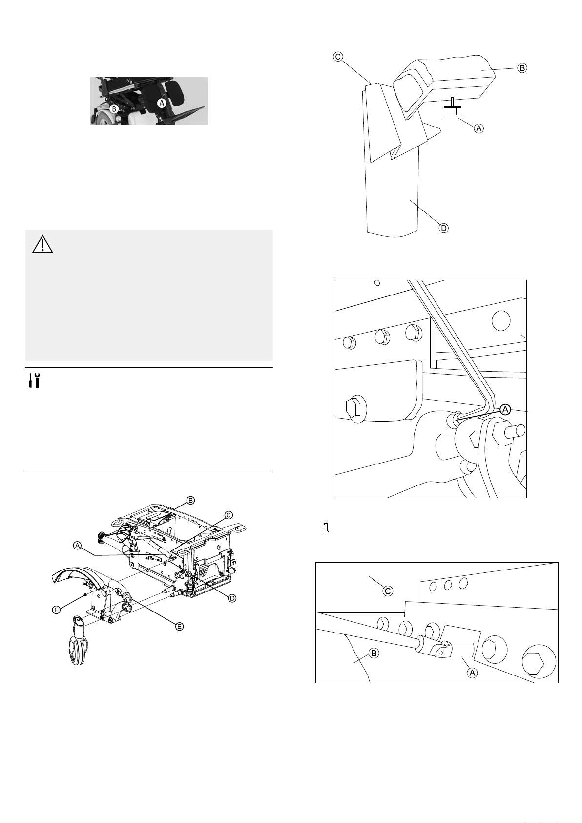
Connectthevoltmeterleadstothechargerconnector
Aonthemobilitydevice.MostdigitalvoltmetersB
arenotaffectedbypolarity .However,analogmeters
(meterswithswingingneedles)canbeandshouldbe
usedcarefully .
Agoodmeterreadingshouldbe25.5to26VDC
withthechairinneutral.
WARNING!
–Whenperformingtheremainingsteps,ensure
yourfeetareclearfromcastersandwall,
otherwiseinjurymayresult.
5.Runthemobilitydeviceinneutralforatleast2minutes.
6.Sitinmobilitydeviceandplaceyourfeetagainstadoor
jam,workbenchorotherstationaryobject.
1532486-L
11

Invacare®TDX®SP2Series
7.Carefullypushtheremoteforward,tryingtodrivethe
mobilitydevicethroughthestationaryobject.Theload
shoulddrawbetween30to40ampsfromthebatteries
for0.3seconds.
Performingthisstepputsaheavyloadon
thebatteriesastheytrytopushthroughthe
stationaryobject.Ifthewheelsspin,havetwo
individuals(oneoneacharm)applyasmuch
downwardpressureaspossibleonthearmsof
themobilitydevice.
8.Readthemeterwhilethemotorsarestrainingto
determinethevoltageunderload.
Ifthevoltagedropsmorethan2voltsfroma
pairoffullychargedbatteriesduringthe0.3
seconds,theyshouldbereplacedregardlessof
theunloadedvoltages.
5.5CheckingBatteryChargeLevel
Thefollowing“Dos”and“Don’ts”areprovidedforyour
convenienceandsafety .
DON’TDO
Don’tperformany
installationormaintenance
withoutrstreadingthis
manual.
Don’tperforminstallation
ormaintenanceofbatteries
inanareathatcouldbe
damagedbybatteryspills.
Don’tmakeitahabitto
dischargebatteriestothe
lowestlevel.
Don’tusechargersor
batteriesthatarenot
appropriateforthechair .
Don’tputnewbatteriesinto
servicebeforecharging.
Don’ttiportiltbatteries.
Don’ttaponclampsand
terminalswithtools.
Readandunderstand
thismanualandany
serviceinformationthat
accompaniesabatteryand
chargerbeforeoperating
thepersonaltransporter .
Movethepersonal
transportertoaworkarea
beforecleaningterminals,
oropeningbatterybox.
Rechargeasfrequentlyas
possibletomaintainahigh
chargelevelandextend
batterylife.
Followrecommendationsin
thismanualwhenselecting
abatteryorcharger.
Fullychargeanewbattery
beforeusing.
Useacarryingstrapto
remove,moveorinstalla
battery.
Pushbatteryclampsonthe
terminals.Spreadclamps
widerifnecessary.
12
1532486-L
Service
6Service
6.1Tighteningtorques
CAUTION!
Damagecanbecausedtothemobilitydevice
duetoimproperlytightenedscrews,nutsor
plasticconnections.
–Alwaystightenscrews,nutsetctothestated
tighteningtorque.
–Onlytightenscrewsornutswhicharenotlisted
herengertight.
Thetighteningtorquesstatedinthefollowinglistarebased
onthethreaddiameterforthenutsandboltsforwhichno
specicvalueshavebeendetermined.Allvaluesassume
dryandde-greasedthreads.
ThreadTighteningtorquein
Nm±10%
M43Nm
M5
M610Nm
M825Nm
M1049Nm
M1280Nm
M14120Nm
M16180Nm
6Nm
Underneathseat
BatteriesbehindfrontshroudA
Fig.6-1
PowermodulebehindrearshroudA
Fig.6-2
Actuatormodules
UNCThreadTighteningtorquein
Nm±10%
1/4”-20
5/16”-20
3/8”-16
7/16”-14
1/2”-13
9/16”-12
5/8”-11
3/4”-1
7/6”-9
1”-8
11–7Nm
22–14Nm
41–25Nm
67–40Nm
100–60Nm
150–90Nm
210–130Nm
370–230Nm
600–370Nm
900–550Nm
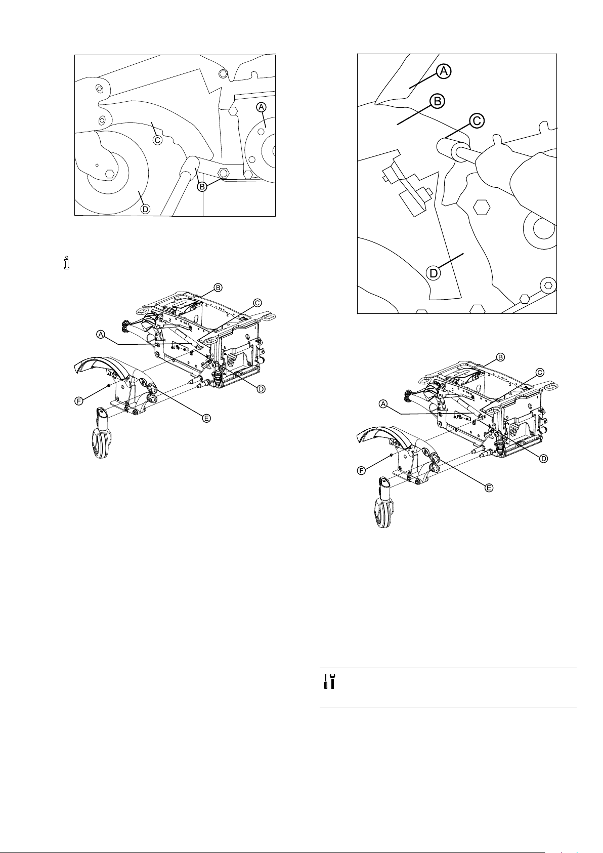
6.2Overviewmobilitydevice
ThisoverviewappliesforTDXSP2mobilitydeviceswith
ModuliteSeat.
Tiltactuator(optional)A
Actuatormodule(optional)B
Lifteractuator(optional)C
Fig.6-3
Lifter
ACTwithLifter
1532486-L13
Invacare®TDX®SP2Series
locatedundertheseat.
Centermountpoweredlegrestsandtiltmodule
G-Trac®Sensor
TheoptionalG-Trac-sensorislocatedbehindtherearshroud.
6.3Chassis
6.3.1Stabilitylock
Replacinggascylinder
CAUTION!
Riskofcrushing
Mobilitydeviceisveryheavy.Injuryhazardto
handsandfeet.
–Useproperliftingtechniques.
Riskofinjurybyuncontrolledmovementof
mobilitydevice
–Switchpowersupplyoff(ON/OFFkey).
–Engagedrive.
–Beforeraisingmobilitydevice,securewheelsby
blockingthemwithwedges.
3.
Fig.6-4
LoosenandremovehandscrewAunderrearlightB
nearwheelD.
4.
Removinggascylinder
•3/16”Allenkey
•5/16“wrenchwithextension
•3/4”wrench
•5/32“Allenkey
•7/16”socketwrench
•Phillipsscrewdriversize2
•T orquewrench5-25Nm(orsimilar)
•Twolongwoodenblocks,min.14x14x30cm
•Threadlockingadhesive,forexampleLoctite242
Fig.6-5
Ifmobilitydeviceisttedwithcableties,remove.
Wheninstalling,makesuretoreplacecableties.
LoosenandremovescrewA.
5.
1.Liftmobilitydeviceupononesideandplacea14cm
highwoodenblockunderbatterycasesothatwheels
areoffthegroundandcanrotatefreely.Useproper
liftingtechniques.
2.Repeatsameprocedureonothersideofmobilitydevice.
14
LoosenandremovescrewAovermudguardBunder
seatframeC.
6.Removebatteriesasdescribedin6.7.6Replacing
batteries,page33and6.7.9Replacingbatteries/replacing
batterycables,page35.
7.Removedrivewheelasdescribedin6.5.6Replacing
drivewheel,page26.
1532486-L
Service
8.
Fig.6-6
LoosenscrewsBnearhubAandcastorDthatx
lowerbeamCtochassis.
Wheninstalling,usethreadlockingadhesive,for
example,Loctite242.
9.
10.
Fig.6-7
RemovenutConupperbeamB,DonmudguardA.
Holdscrewinplace.
11.
RotatetopwalkingbeamEsothatyoucanreachthe
screwDonthegascylinderthroughthedrillholeC
inbatterybox.
RemovenutF.Holdscrewinplace.
12.PushscrewDtowardsbatteryboxsothatgascylinder
Aisseparatedfromwalkingbeam.
13.Pushgascylinderagainstbatterybox.
14.Raiserearaxlesothatgascylinderisactivatedandthen
retractcylinder.
15.Pushgascylindertotherearandpullitoffbatterybox.
Installinggascylinder
1.Installpartsinreverseorder .
Replacingsettingscrew
•1/4“wrench
•Twolongwoodenblocks,min.14x14x30cm
•Feelergaugewith2mm
1532486-L15
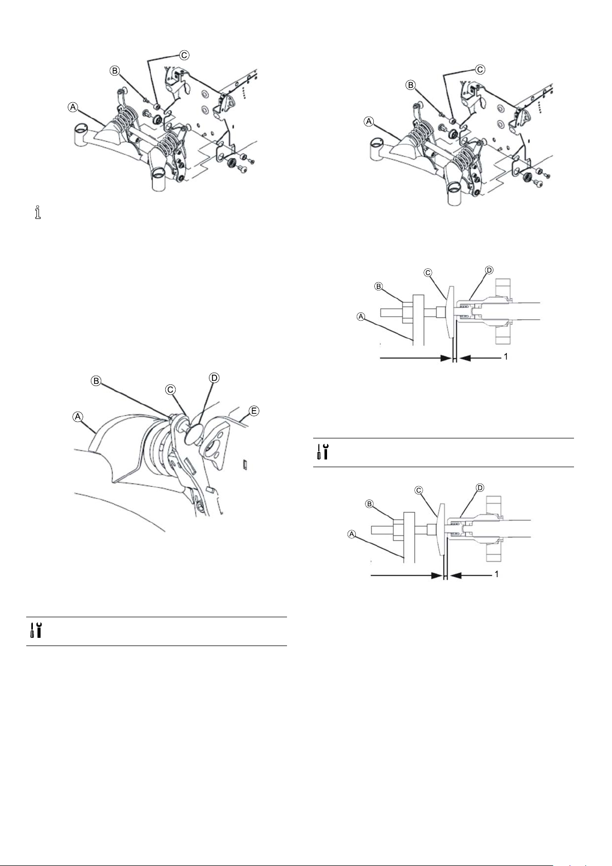
Invacare®TDX®SP2Series
1.ScrewnewsettingscrewDintoholderC.
2.
Invacarerecommendsalwaysreplacingbothsetting
screwssimultaneouslytoensurethatthemobility
deviceworksperfectly.
Removingsettingscrew
1.Liftthemobilitydeviceupononesideandplacea14
cmhighwoodenblockunderthebatterycasesothat
thewheelsareoffthegroundandcanrotatefreely.Use
properliftingtechniques.
2.Repeatsameprocedureonothersideofmobilitydevice.
3.Removebothanti-tipsystemprotectivecaps.The
protectivecapsonanti-tipsystemwilleitherbeheld
usingascreworacabletiedependingonthemobility
device'sdateofmanufacture.
4.
InserttwoscrewsBtogetherwithwashersC.
3.Tightenscrews.
4.Removewoodenblockfromundermobilitydevice,so
thatallcastersareincontactwithoor .
5.
RotatesettingscrewCuntilthereisaspaceof2mm
(1)betweenitandthegascylinderD.
6.InstalllocknutBandtighten.
7.Installtwoprotectivecaps.
Adjustingsettingscrew
•1/4“wrench
•Feelergaugewith2.0mm
LoosentwoscrewsBandremovetogetherwithwashers
C.
5.LoosenandremovelocknutBofsettingscrewD.
6.RotatesettingscrewDtowardsbatterycaseuntilyou
canremoveitfromitsholderC.
Installingsettingscrew
•1/4”wrench
•Feelergaugewith2mm
1.Removebothprotectivecapsofstabilitylocksystem.
Theyareheldusingascreworacabletiedependingon
themobilitydevice’ sdateofmanufacture.
2.Ensurethatmobilitydeviceiscontactingoorwithall
itswheelsandcasters.
3.LoosenandremovelocknutB.
4.RotatesettingscrewCuntilthereisaspaceof2.0mm
(1)betweenitandgascylinderD.
5.InstalllocknutBandtighten.
6.Repeatforothersettingscrew.
7.Installtwoprotectivecaps.
161532486-L
 Loading...