

Invacare Robin Series, Robin Mover, Robin Service Manual
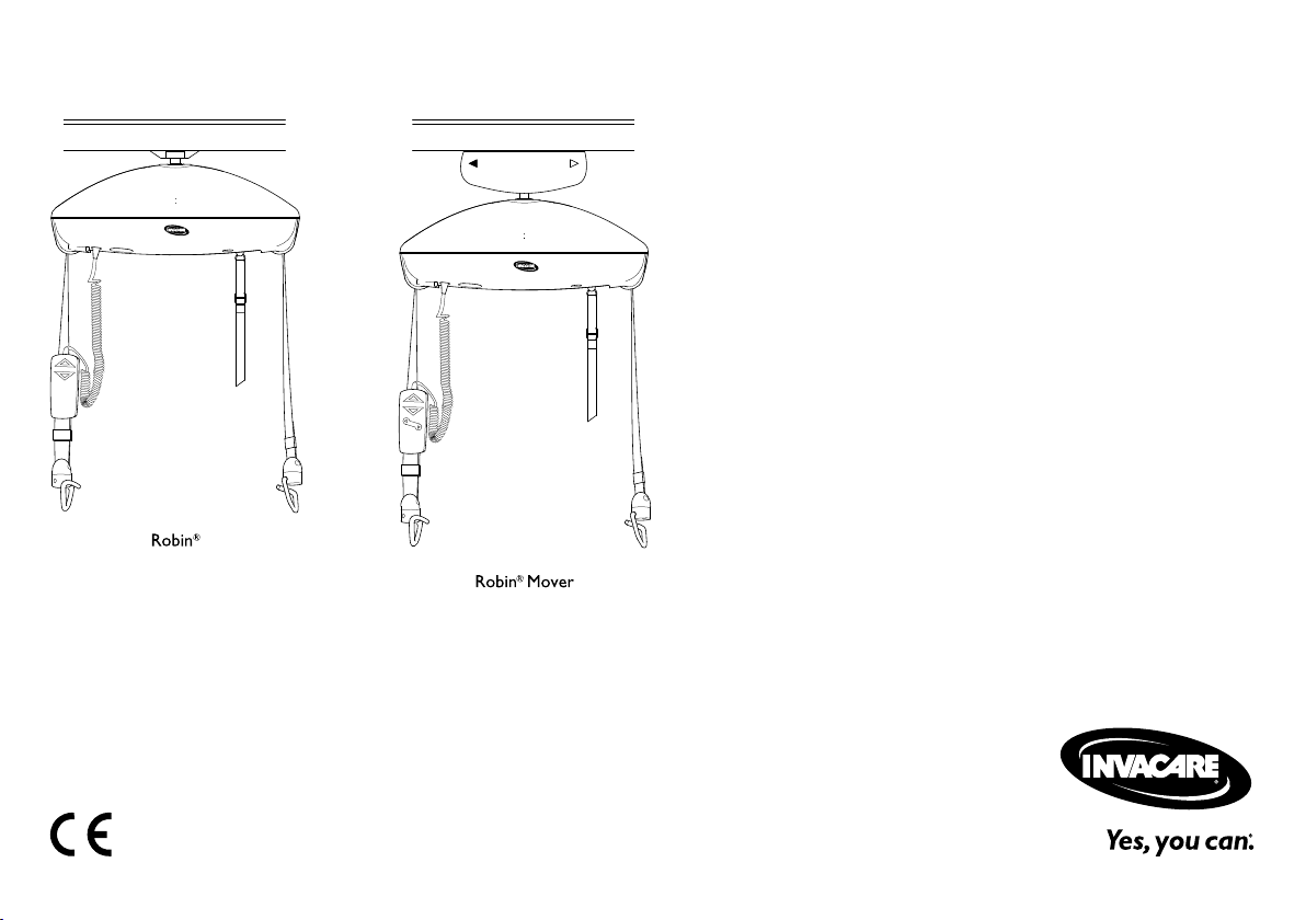
Invacare®Robin®
Robin®,Robin®Mover
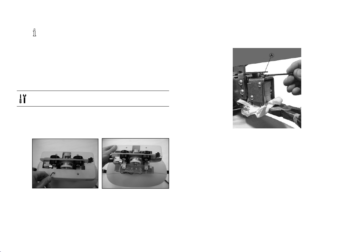
enCeilingHoist
ServiceManual.............................3
daLøftemotor
Servicemanual..............................35
frLève-personnesurrail
Manueldemaintenance.....................69
nlPlafondlift
Servicehandleiding..........................105
no
Takmontertløfter
Servicehåndbok.............................139
svTaklyft
Servicemanual..............................171
DEALER:Keepthismanual.
TheproceduresinthismanualMUSTbeperformedbyaqualied
technician.

©2018InvacareCorporation
Allrightsreserved.Republication,duplicationormodicationinwholeorinpartisprohibited
withoutpriorwrittenpermissionfromInvacare.Trademarksareidentiedby™and®.Alltrademarks
areownedbyorlicensedtoInvacareCorporationoritssubsidiariesunlessotherwisenoted.
—
Allerettighederforbeholdes.Helellerdelvisgengivelse,kopieringellerændringerforbudtuden
forudgåendeskriftligtilladelsefraInvacare.Varemærkerermarkeretmed™og®.Allevaremærker
ejesafellerergivetilicenstilInvacareCorporationellerdennevirksomhedslialer,medmindre
andetfremgår .
—
Tousdroitsréservés.Larepublication,laduplicationoulamodicationdetoutoupartieduprésent
documentestinterditesansl'accordécritpréalabled'Invacare.Lesmarquescommercialessont
identiéespar™et®.Touteslesmarquescommercialessontdétenuesparoucédéessouslicence
àInvacareCorporationousesliales,saufstipulationcontraire.
—
Allerechtenvoorbehouden.Herpublicatie,duplicatieofgeheleofgedeeltelijkewijzigingisverboden
zondervoorafgaandeschriftelijketoestemmingvanInvacare.Handelsmerkenzijnteherkennenaan
™en®.AllehandelsmerkenzijneigendomvanofgelicentieerdaanInvacareCorporationofhaar
dochterondernemingen,tenzijandersaangegeven.
—
Medenerett.Deterforbudtårepublisere,kopiereellerendreheleellerdeleravdenneveiledningen
utenatdetpåforhånderinnhentetskriftligtillatelsefraInvacare.Varemerkererangittmed™og
®.AllevaremerkereiesavellerlisensierestilInvacareCorporationellertilhørendedatterselskaper
medmindreanneterangitt.
—
Medensamrätt.Innehålletfårintegesutpånytt,mångfaldigasellerförändrasheltellerdelvisutan
föregåendeskriftligttillståndfrånInvacare.Varumärkenbetecknasmed™och®.Samtligavarumärken
tillhörellerärlicensieradetillInvacareCorporationellerdessdotterbolagomingentingannatanges.

Contents
1General.........................................4
1.1Introduction..................................4
1.2Symbolsinthismanual..........................4
1.3Safetyinformation..............................4
2Components......................................6
2.1Mainpartsoftheceilinghoist.....................6
2.2Accessories...................................6
2.3Spareparts...................................7
3Service..........................................8
3.1Installingtheceilinghoisttotherailsystem...........8
3.1.1InstallingRobin®............................8
3.1.2InstallingRobin®Mover.......................9
3.2Dismountingtheceilinghoist......................10
3.2.1DismountingRobin®..........................10
3.2.2DismountingRobin®Mover....................11
3.3Replacingthehandcontrol.......................13
3.4Removingthehoistcover........................13
3.5ReplacingStrapandHookAssemblies...............13
3.6Replacingthebattery...........................14
3.7ReplacingthePCB(PrintedCircuitBoard).............15
3.8Replacingthefuse..............................16
3.9Adjustingthesolenoiduntilthehoisttraverses........17
3.10AdjustingLooseStrapSwitch.....................18
3.11ReplacingtheTwinSpeedSwitch..................19
3.12ReplaceContactDiscforRobin®Mover.............20
4Maintenance.....................................22
4.1ChargingtheBattery............................22
4.2BatteryMaintenance............................22
4.2.1StorageCharacteristics........................23
4.2.2StorageT emperature.........................23
4.2.3StorageTime...............................23
4.2.4StorageHumidity............................24
4.2.5CapacityRecovery...........................24
4.3SafetyInspectionChecklist........................25
4.4LOLERStatement...............................26
5Troubleshooting...................................27
5.1TroubleshootingTable...........................27
5.2Indicatorlightandaudiosignal....................29
5.3CheckingLooseStrapFunction....................29
5.4CheckingTwinSpeedFunctionality..................29
5.5T akingVoltageReadings.........................30
6T echnicalData....................................32
6.1Therailsystem................................32
6.2Dimensionsandweight..........................32
6.3ElectricalSystem...............................33
6.4Environmentalconditions........................33
6.5Electromagneticcompliance(EMC)information........34
6.5.1Guidanceandmanufacturer’sdeclaration..........34
Invacare®Robin®
1General
1.1Introduction
Thisdocumentcontainsimportantinformationabout
assembly,adjustmentandadvancedmaintenanceofthe
product.Toensuresafetywhenhandlingtheproduct,read
thisdocumentandtheusermanualcarefullyandfollow
thesafetyinstructions.
FindtheusermanualonInvacare’swebsiteorcontactyour
Invacarerepresentative.Seeaddressesattheendofthis
document.
Invacarereservestherighttoalterproductspecications
withoutfurthernotice.
Beforereadingthisdocument,makesureyouhavethe
latestversion.YoundthelatestversionasaPDFonthe
Invacarewebsite.
Forpre-saleanduserinformation,seetheusermanual.
Formoreinformationabouttheproduct,forexample
productsafetynoticesandproductrecalls,contactyour
Invacarerepresentative.Seeaddressesattheendofthis
document.
1.2Symbolsinthismanual
Symbolsandsignalwordsareusedinthismanualandapply
tohazardsorunsafepracticeswhichcouldresultinpersonal
injuryorpropertydamage.Seetheinformationbelowfor
denitionsofthesignalwords.
WARNING
Indicatesahazardoussituationthatcouldresult
inseriousinjuryordeathifitisnotavoided.
CAUTION
Indicatesahazardoussituationthatcouldresult
inminororslightinjuryifitisnotavoided.
IMPORTANT
Indicatesahazardoussituationthatcouldresult
indamagetopropertyifitisnotavoided.
Tips
Givesusefultips,recommendationsand
informationforefcient,trouble-freeuse.
Tools
Identiesrequiredtools,componentsanditems
whichareneededtocarryoutcertainwork.
1.3Safetyinformation
WARNING!
Theproceduresinthisservicemanual,mustbe
performedbyaspecializeddealerorqualied
servicetechnician.
–Donothandlethisproductoranyavailable
optionalequipmentwithoutrstcompletely
readingandunderstandingtheseinstructions
andanyadditionalinstructionalmaterial
suchasusermanuals,installationmanualsor
instructionsheetssuppliedwiththisproduct
oroptionalequipment.
4
1586747-C

Theinformationcontainedinthisdocumentis
subjecttochangewithoutnotice.
General
1586747-C5
Invacare®Robin®
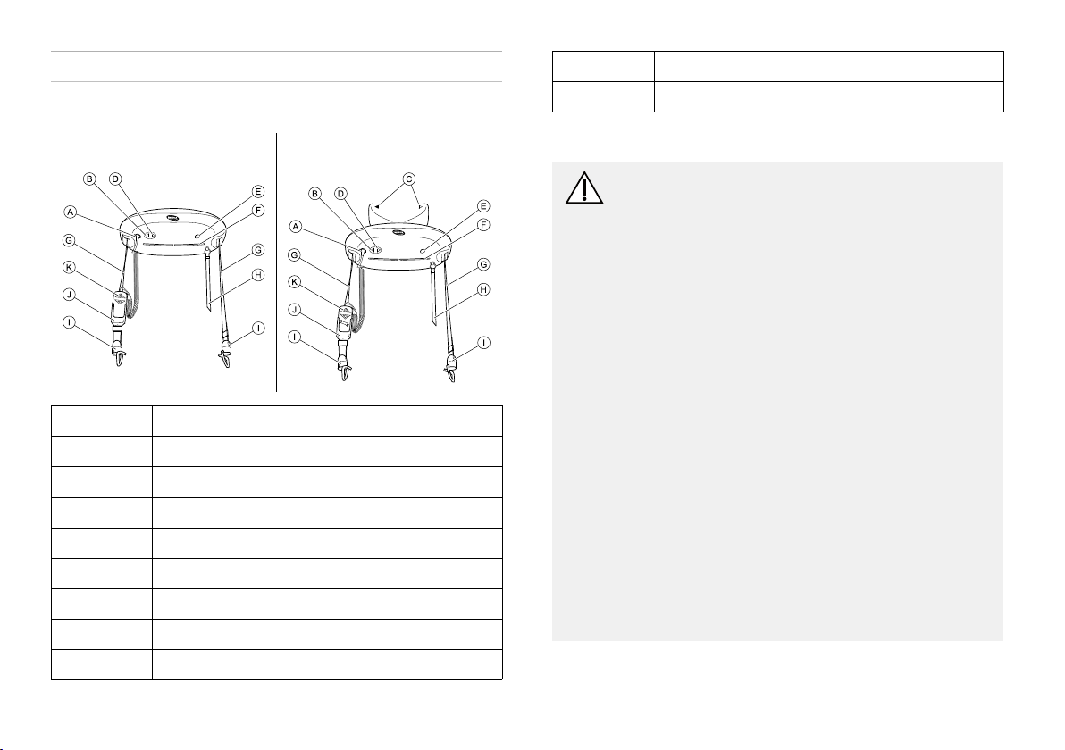
2Components
J
K
Retainerforhandcontrol(accessory)
Handcontrol
2.1Mainpartsoftheceilinghoist
Robin®Robin®Mover
A
B
C
D
E
F
G
H
I
61586747-C
Connectionforhandcontrol
ControlbuttonUP
DirectionalarrowsonRobin®Mover
ControlbuttonDOWN
Connectionforexternalback-upbattery
Indicatorlight
Liftingstraps
Redemergencystrap
Straphooks
2.2Accessories
CAUTION!
Compatibilityofslingsandspreaderbars/strap
hooks
Invacareusesa"LoopandCoatHangerSpreader
Bar/StrapHookSystem"asdomanyother
manufacturers.Thereforeothersuitablepatient
transfersystems(slings),manufacturedbyother
companies,canbeusedontheInvacarepatient
liftrangeaswell.
Howeverwedorecommend:
–Ariskassessmentisalwaystobecarriedoutby
aprofessionalpriortoissuingliftingequipment.
ItisimportantthattheTask,Individual,Load,
EnvironmentandEquipmentareconsideredin
theriskassessment.
–Alwayschoosetheslingdesignandsize
accordingtothepatient’sweight,sizeand
physicalabilitywhilstconsideringthetypeof
transfertobecarriedout.
–Doonlyuseslingsthataresuitablefora"Loop
andCoatHangerSpreaderBar/StrapHook
System".
–Donotuseslingsfor"KeyholeSpreaderBar"or
for"TiltingFrameSpreaderBar"designs.
Availableaccessories
•2-and4-pointspreaderbarincludingexiscopeversion

•Stretcherforhorizontallift
•Scaleincludingspreaderbar
•Holderforhandcontrol
•Batterycharger
•Chargerset(chargerandholderforhandcontrol)
•Extensionstrapsandextensioncablesforhandcontrol
•Externalback-upbattery
•Chargerforexternalback-upbattery
•Slingmodelsfor“LoopandCoatHangerSpreaderBar
System”:
–Fullbodysupportslings–withoutheadsupport
–Fullbodysupportslings–withheadsupport
–Slingsfordress/toileting–withorwithouthead
support
–Slingsforamputee
–Slingsforwalkingtraining
2.3Spareparts
AnelectronicsparepartscatalogueisavailableonInvacare’s
website.Ifyoudon’thaveaccess,contactyourInvacare
representative(seeaddressesattheendofthismanual)for
aprintedsparepartscatalogue.
Components
1586747-C
7
Invacare®Robin®
3Service
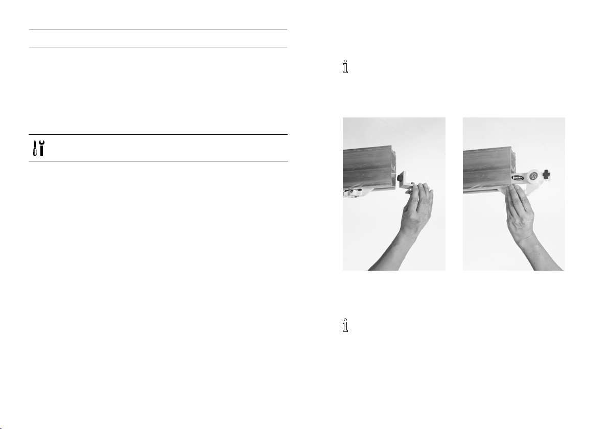
3.1Installingtheceilinghoisttotherailsystem
Robin®requiresatrolley ,guidingtheceilinghoistintherail
system.Robin®Moverhasthetrolleybuilt-inandcanbe
installeddirectlytotherailsystem.
3.1.1InstallingRobin®
Tools:4mmAllenkey;17mmsocketwrench
1.Toinstallthetrolley,removetheendstopthatis
attachedtotherailsystem.
Insomecountries/localareas,thereisa
demandfordoublesecuringoftheendstops.If
anextrasecuringscrewisinstalled,removethis
screwbefore.
2.Insertthetrolleyintotherail(nomatterwhichway,as
thetrolleyissymmetric).
3.Re-inserttheendstop.
Insomecountries/localareas,thereisademand
fordoublesecuringoftheendstops.Ifanextra
securingscrewisrequired,installthisscrew.See
alsoEndStop.
81586747-C
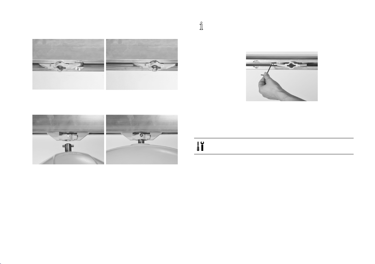
Service
4.LocatethehoisttrolleyattheØ32mmroundrecess
intherail.
5.Liftthehoistandpushthesuspensionpinthroughthe
trolleyopening.
6.Turnthehoistby90degreestoxitinthetrolley.
7.Connectthehandcontrol.
8.Adjustthelengthoftheemergencystop/loweringcord
towithintheuser’sreach.
Ifthereisexcessiveresistance,orifthetrolley
unintentionallyrollsbyitselfduetoimbalanceinthe
railsuspensions,adjustthefrictionbrakeusinga4
mmAllenkey.
3.1.2InstallingRobin®Mover
Thetrolleyisbuilt-inonthehoist,andcanthereforenot
bepreinstalledintherail.
Tools:4mmAllenkey;17mmsocketwrench
1.Removetheendstop.
1586747-C9
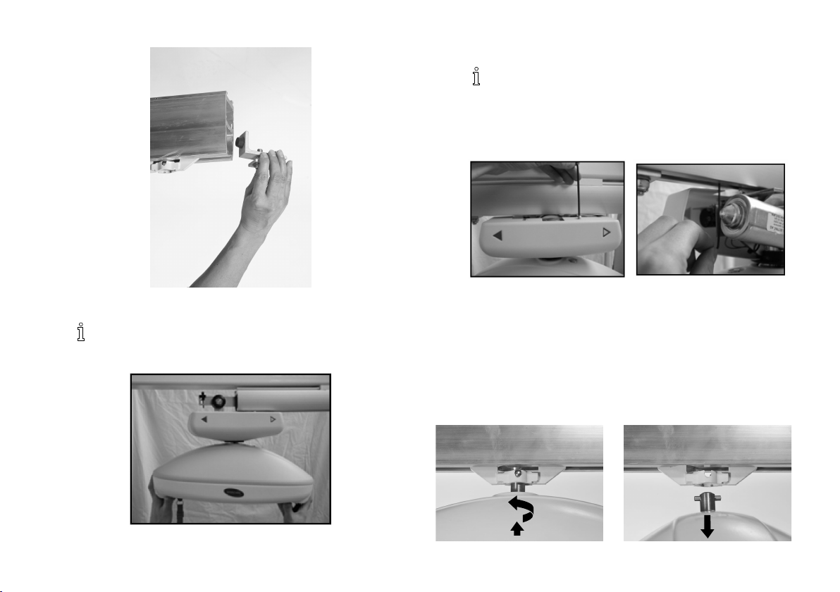
Invacare®Robin®
3.Installtheendstop.
Tightentheboltto30Nm.
4.Iftoomuchresistanceisexperiencedwhenthehoistis
pulled,orthehoistmovestoofreelyandunintentionally,
adjustthefrictionbrake.
2.Insertthewheelsofthehoistintotherail.
Thedirectionthehoistfacesdoesnotmatter
5.Connectthehandcontrol.
6.Adjustthelengthoftheemergencystop/loweringcord
towithintheuser’sreach.
duringinstallation.
3.2Dismountingtheceilinghoist
3.2.1DismountingRobin®
Removetheceilinghoistfromthetrolley
101586747-C
Service
1.Liftthehoistslightlyandpushthesuspensionpinout
ofitsholderinthetrolley.
2.Turnthehoistby90degreesandpullitoutofthe
trolley.
Removethetrolleyfromtherail
1.Removetheendstop.
2.Slidethetrolleyoutoftherail.
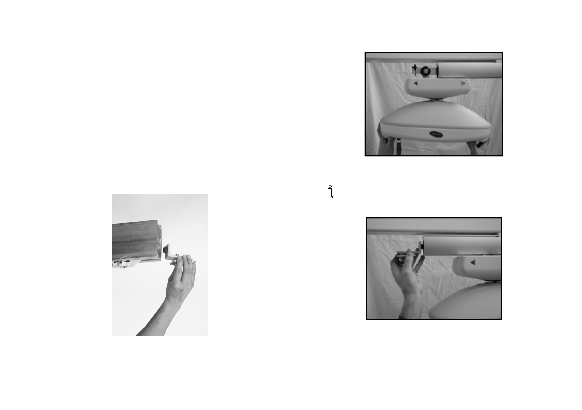
3.2.2DismountingRobin®Mover
1.Pulltheemergencystraptopreventaccidentalactivation
oftheceilinghoistafterithasbeendismountedfrom
therail.
2.Removetheendstop.
3.Slidethewheelsofthehoistoutoftherail.
4.Installtheendstop.
Tightentheboltto30Nm.
5.Ifremovingthehoistfromtherailmotor,performthe
followingsteps:
1586747-C
11
Invacare®Robin®
Whenreplacingthebatteryorperforming
service,itisalsonecessarytoremovethehoist
fromtherailmotor.
a.Removethescrewssecuringtheplasticshellsfrom
therailmotor.
b.Pulltheplasticshellsawayfromeachotherto
removethemfromtherailmotor .
c.RemovetheM6screwsecuringtherailmotortothe
hoist.
12
d.Separatetherailmotorfromthehoist.
CAUTION!
Riskofdamage
Itispossibletoremovethehoistfromtherail
motorwithoutremovingtherailmotorfromthe
railsystem.Toavoiddamagetothehoist:
–Alwayssupportthehoistwhenremovingthe
M6screw.
1586747-C
Service
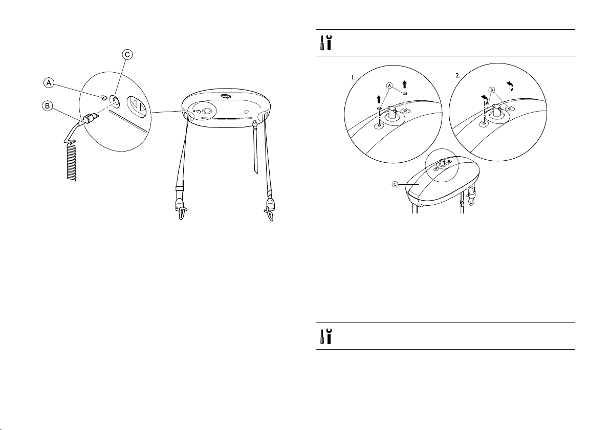
3.3Replacingthehandcontrol
1.SlideandholdlockingleverAawayfromtheaperture
C.
2.PulltheplugBoutoftheaperture.
3.Insertplugofthenewhandcontrolintoaperture.Make
sure,theplugisinthecorrectorientationwiththeslot
upwards(seeimage).
4.ReleaseleverA,sothatthegateclosesandholdthe
plugintheaperture.
Tools:Screwdriver ,slotted
1.RemoveprotectioncapsA.Usengersor ,ifrequired,
useascrewdrivercarefully.
2.UntightenscrewsB,usingascrewdriver .
3.RemovethecoverCfromthehoist.
Toclosethehoistcover,tightenthescrewsandattachthe
protectioncapsagain.
3.5ReplacingStrapandHookAssemblies
3.4Removingthehoistcover
Beforeremovingthehoistcover ,pulltheredemergency
straptoturnoffthehoistandremovethehoistfromthe
tracksystem.Referto:
•3.2Dismountingtheceilinghoist,page10
1586747-C13
Tools:10mmsocketkey;5mmhex/Allenkey
1.Withtheceilinghoistinthetrack,lowerthestrapsto
theirlowestpointusingthehandcontrol.
2.Pulltheredemergencystraptoperformanemergency
stop.Donotperformemergencylowering.
Invacare®Robin®
3.Removehoistfromtrack.Referto3.2Dismountingthe
ceilinghoist,page10.
4.Removethecover.Referto3.4Removingthehoist
cover,page13.
5.Resettheemergencystopbypressingtheresetbutton.
6.CheckthatthestrapAiscompletelyunwoundas
shownintheimage.Ifnot,windthestrapsoutusing
theUP/DOWNbuttononthehandcontrol.
7.AlignthestrapretainingboltsBwiththeapertureinthe
chassisusingtheUP/DOWNbuttononthehandcontrol.
8.Pulltheredemergencystrapagain.
9.Removestrapbolts,usinga10mmsocketkeyanda
5mmhex/Allenkey.
10.Removethestrapthroughguidecylinder .
11.Insertanewstrapthroughguidecylinderandassemble
usingthestrapretainingbolts(Torque:4Nm).Make
surethatthenewstrapisfedovertheslackstrap
switchwire.
12.Re-mountthecover,re-assemblethehoisttothetrack
andresettheemergencystop.
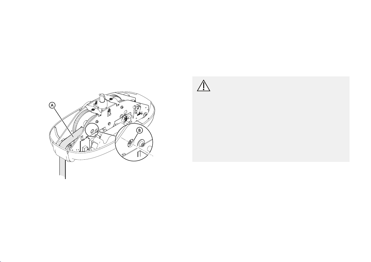
3.6Replacingthebattery
CAUTION!
StaticelectricitycandamagethePCBsinsidethe
hoist.
Beforeworkingintheinsideofthehoist:
–Pulltheredemergencystraptoturnoffthe
hoist.
–Removethehoistfromthetracksystem.(Refer
to3.2Dismountingtheceilinghoist,page10)
–Removethecoverfromthehoist.(Referto3.4
Removingthehoistcover,page13
–Ananti-staticmatmustbeusedwhenworking
insidetheceilinghoist.
)
14
1586747-C
1.UnplugthewiresA.
2.RemovethebatterypackB.
3.Insertanewbatterypack.
UseonlyInvacarerecommendedbatteries.
4.PluginthewiresA.
5.Re-assemblethehoistandresettheemergencystop.
Service
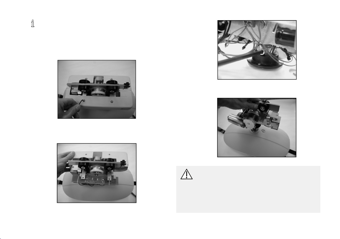
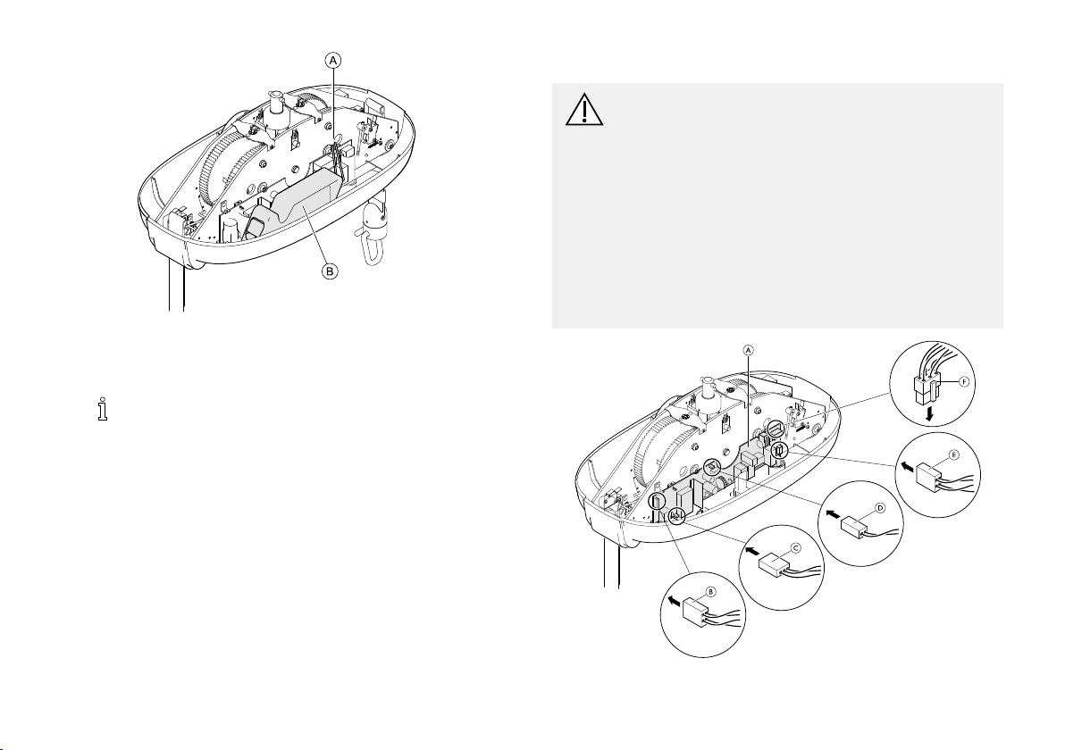
3.7ReplacingthePCB(PrintedCircuitBoard)
CAUTION!
StaticelectricitycandamagethePCBsinsidethe
hoist.
Beforeworkingintheinsideofthehoist:
–Pulltheredemergencystraptoturnoffthe
hoist.
–Removethehoistfromthetracksystem.(Refer
to3.2Dismountingtheceilinghoist,page10)
–Removethecoverfromthehoist.(Referto3.4
Removingthehoistcover,page13)
–Ananti-staticmatmustbeusedwhenworking
insidetheceilinghoist.
1586747-C15
Invacare®Robin®
1.Removethebattery.Refertosteps1and2inchapter
3.6Replacingthebattery,page14.
2.RemoveallplugsB,C,D,EandFfromthePCBA.
3.ReleasethePCBAfromtheretainingholdersbygently
pressingdownthelockingclipsandleveringthePCB
slightlyawayfromthechassisplate.
4.LiftthePCBuptoremove.
5.PlacethenewPCBintothechassisandpressitslightly
againstthechassisplateuntiltheretainingholderssnap
intoplace.
6.ConnecttheplugsB,C,D,EandFtothenewPCB.
7.Re-insertbattery,re-assemblethehoistandresetthe
emergencystop.
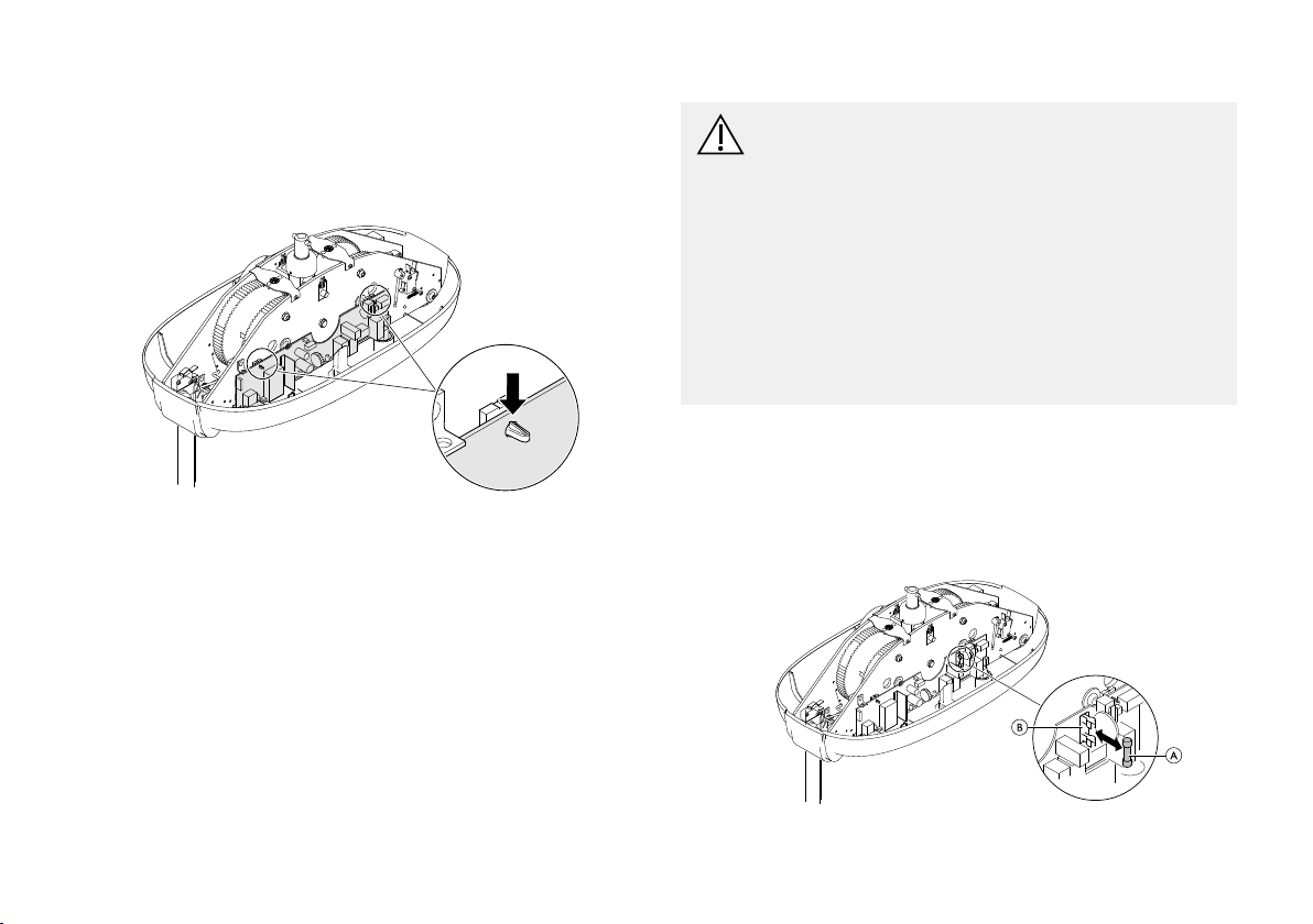
3.8Replacingthefuse
CAUTION!
StaticelectricitycandamagethePCBsinsidethe
hoist.
Beforeworkingintheinsideofthehoist:
–Pulltheredemergencystraptoturnoffthe
hoist.
–Removethehoistfromthetracksystem.(Refer
to3.2Dismountingtheceilinghoist,page10)
–Removethecoverfromthehoist.(Referto3.4
Removingthehoistcover,page13)
–Ananti-staticmatmustbeusedwhenworking
insidetheceilinghoist.
1.Removethehandcontrol.Refertochapter3.3Replacing
thehandcontrol,page13
2.Removethebattery.Refertosteps1to3inchapter3.6
Replacingthebattery,page14.
3.GentlypullthefuseAstraightoutawayfromthe
holderB.
161586747-C
Service
4.Insertnewfuse.
Makesureonlyafusewithcorrectrating10A
250Vslowblowisused.
5.Re-insertbattery,re-assemblethehoist,insertthehand
controlandresettheemergencystop.
3.9Adjustingthesolenoiduntilthehoist
traverses
Robin®Moveronly.
4mmAllenkey;7mmspanner
1.Pulltheredemergencystrap.
2.Withtheceilinghoistremainingonthetrack,remove
bothplasticshells:
3.Usingacloth,protectthesolenoidplungerwhilst
clampingwithgripsatthesametime.
Usinga7mmspannerraisethenutAbyturning
anti-clockwise2completeturns.
4.Fortesting,restrainthehoistwithonehandwhilst
pressingtheLeftorRightbuttononthehandcontrol.
Thereshouldbegoodcontactbetweenthewhitedrive
wheelandtheundersideofthetrack.Ifnot,repeat
step3.
5.Reassembletheplasticshells.Ensurethecorrect
orientation,withclearancefortheplateabovethe
solenoidtomoveupanddownfreely.Seeimagesin
step2.
a.Removethescrewssecuringtheplasticshellsfrom
therailmotor.
b.Pulltheplasticshellsawayfromeachotherto
removethemfromtherailmotor .
1586747-C
17
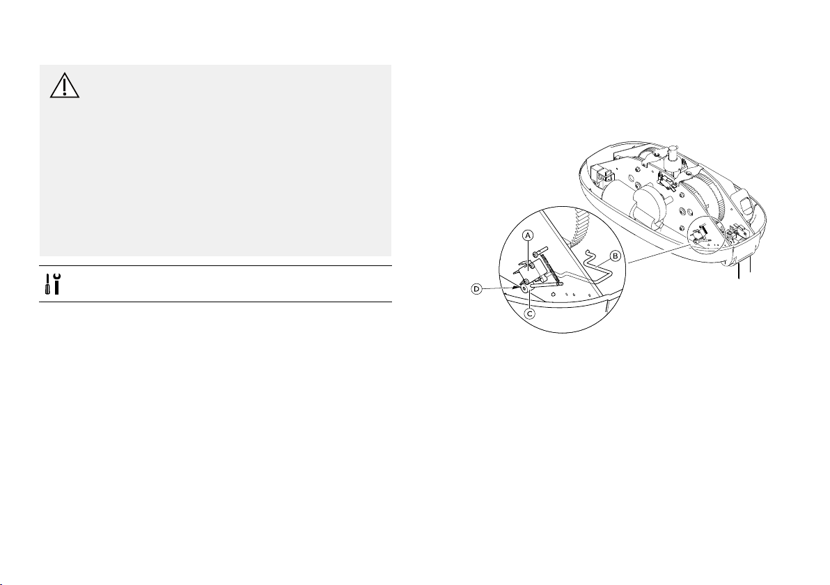
Invacare®Robin®
3.10AdjustingLooseStrapSwitch
CAUTION!
StaticelectricitycandamagethePCBsinsidethe
hoist.
Beforeworkingintheinsideofthehoist:
–Pulltheredemergencystraptoturnoffthe
hoist.
–Removethehoistfromthetracksystem.(Refer
to3.2Dismountingtheceilinghoist,page10)
–Removethecoverfromthehoist.(Referto3.4
Removingthehoistcover,page13)
–Ananti-staticmatmustbeusedwhenworking
insidetheceilinghoist.
2mmAllenkey
1.Placethehoistonasurface(suchasthecornerofa
table)sothatthehoistissupportedyetthestrapsand
handcontrolarefreehanging.Ensurethehoistissafe
andcannotslip/fallofthetable.
2.LocatetheloosestrapswitchAandvisuallycheckif
thereisclearancebetweencolletCandchassis.
a.Ifnot:whilstretainingthegeometryoftheslack
strapwireBandcolletarm,loosenthecolletgrub
screwDwitha2mmAllenkey.
b.Createclearancebetweencolletandchassis.
c.Retightenthecolletgrubscrew.
3.Testtheloosestrapfunction.Refertochapter5.3
CheckingLooseStrapFunction,page29.Thistestcan
becarriedoutwiththehoistremainingonthetable.
Ifthefaultisrectied,re-assemblethehoist.Ifnot,
continuewithstep4.
181586747-C
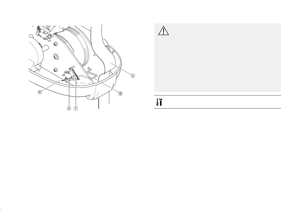
Service
4.Adjusttensionontheslackstrapwire:
a.LoosenthecolletgrubscrewDwitha2mmAllen
key.NotethespringFwillnowpullthecolletarm
Cagainsttheswitchsoitisopencircuit.
b.LiftthestrapEofftheslackstrapwireBandlift
uptheslackstrapwire.
c.RetightenthecolletgrubscrewD.
5.Testtheloosestrapfunction.Refertochapter5.3
CheckingLooseStrapFunction,page29.Thistestcan
becarriedoutwiththehoistremainingonthetable.
6.Ifthefaultisrectied,re-assemblethehoistandreset
theemergencystop.
3.11ReplacingtheTwinSpeedSwitch
CAUTION!
StaticelectricitycandamagethePCBsinsidethe
hoist.
Beforeworkingintheinsideofthehoist:
–Pulltheredemergencystraptoturnoffthe
hoist.
–Removethehoistfromthetracksystem.(Refer
to3.2Dismountingtheceilinghoist,page10)
–Removethecoverfromthehoist.(Referto3.4
Removingthehoistcover,page13)
–Ananti-staticmatmustbeusedwhenworking
insidetheceilinghoist.
T10T orxscrewdriver
1586747-C19
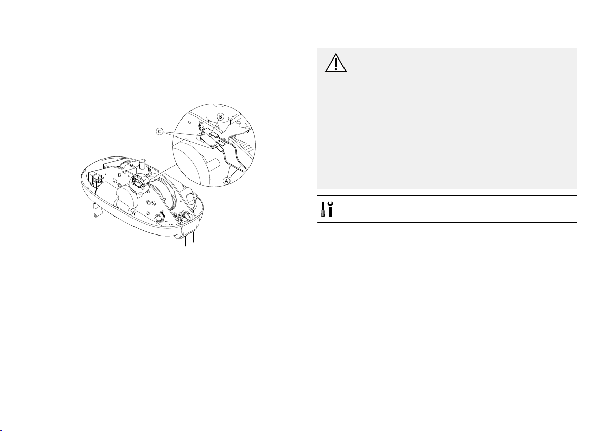
Invacare®Robin®
1.Placethehoistonasurface(suchasthecornerofa
table)sothatthehoistissupportedyetthestrapsand
handcontrolarefreehanging.Ensurethehoistissafe
andcannotslip/fallofthetable.
2.RemovethetwoyellowcablesAfromthetwinspeed
switchB.
3.RemovethetwoscrewsC.
4.AttachthenewtwinspeedswitchwithscrewsC.
ConnecttheyellowcablesA.Ensure,theyare
connectedtothebottomandtopterminals.
5.Re-assemblethehoistandresettheemergencystop.
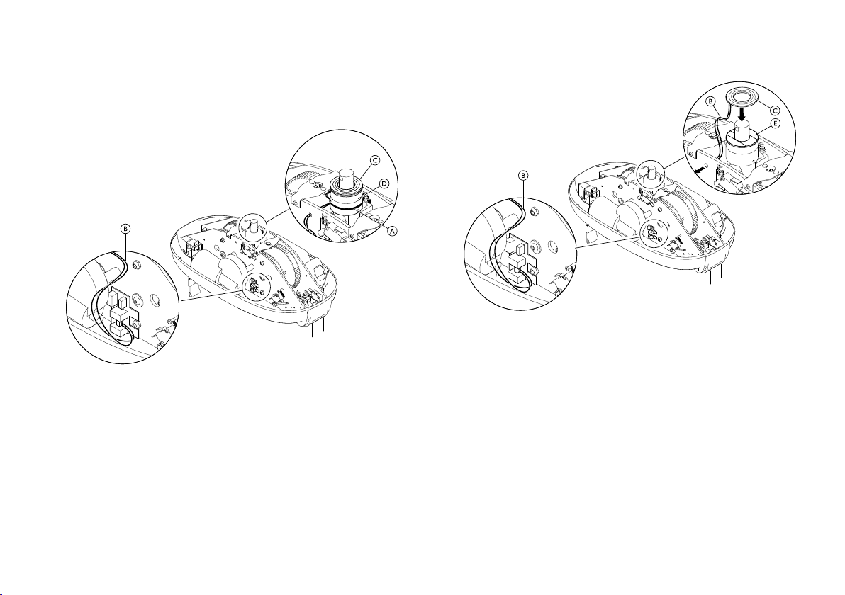
3.12ReplaceContactDiscforRobin®Mover
CAUTION!
StaticelectricitycandamagethePCBsinsidethe
hoist.
Beforeworkingintheinsideofthehoist:
–Pulltheredemergencystraptoturnoffthe
hoist.
–Removethehoistfromthetracksystem.(Refer
to3.2Dismountingtheceilinghoist,page10)
–Removethecoverfromthehoist.(Referto3.4
Removingthehoistcover,page13)
–Ananti-staticmatmustbeusedwhenworking
insidetheceilinghoist.
Screwdriver
201586747-C
Service
1.RemovethecabletieA.
2.RemovethecontactdisccablesBfromtheMoverPCB,
usingaterminalscrewdriver.Notebrowncabletopand
bluecablebottom.
Feedthecablesthroughthechassisplate.
3.Carefullyseparateandremovethecompletecontact
discCfromthesuspensionbaseDbyreleasingthe
self-adhesivetape.
4.Remove,cleanofftheremainsoftheselfadhesivetape.
5.FitthenewselfadhesivetapeEandthenewcontact
discC.
6.FeedthecablesBthroughthechassisplateand
connectthemtotheMoverPCB.
7.Re-assemblethehoistandresettheemergencystop.
1586747-C
21

Invacare®Robin®
4Maintenance
4.1ChargingtheBattery
Ifthechargestatusbecomeslow ,anaudibleindicator
soundsandtheindicatorlamponthebottomoftheceiling
hoistashes(seealso5.2Indicatorlightandaudiosignal,
page29).Whenthishappens,thereisusuallysufcient
powertolowerthepatient.
Itisnotpossibletousethehoistwhilethebattery
ischarging.
1.Finishthecurrentliftinprogress
Ifthecurrentliftinprocessdischargesthebattery
completely,anexternalbackupbatterymaybeused
totemporarilypowerthelift.SeeUsingtheexternal
back-upbattery.
2.Movetheceilinghoisttothechargingstation.
3.Assurethatthehandcontrolandchargingstationare
cleananddrybeforecharging
4.Placethehandcontrolintothechargingstation.
Ayellowindicatorlamponthechargerindicates
thehandcontrolisconnected.Theindicatorlamp
illuminatesredwhilecharging.
5.Whenfullycharged,theindicatorlamponthecharger
turnsgreen.
Aslongastheceilinghoistisnotinuse,leavethehand
controlinthechargingstation.
6.Tousetheceilinghoist,removethehandcontrolfrom
thecharger .
22
Keepingthebatterieschargedguaranteeshoist
functionalityandmaintainsthebatterytoensure
alonglifetime.
Iftheaudibleindicatorbeepsandtheblueindicator
onthehoistashesafterthehoisthasbeenfully
chargedandonlybeeninuseforashortperiodof
time,thebatterymayneedexerciseorreplacement.
See4.2BatteryMaintenance,page22
.
Iftheceilinghoistwillnotbeusedformorethan
4weeks,Invacarerecommendsdisconnectingthe
chargerandpullingtheemergencystop.
Thechargerisconnectedtothemainswithamains
plug.Makesurethatthemainsplugisaccessible
andcanbeunpluggedifrequired.
4.2BatteryMaintenance
Iftheaudibleindicatorbeepsandtheblueindicatoronthe
hoistashesafterthehoisthasbeenfullychargedand
onlybeeninuseforashortperiodoftime,thebattery
mayneedtobeexercised.
Toenablethebatterytochargefully ,thebatteryshouldbe
exercisedfromtimetotime.
Followingalongperiodofstorage,itcouldalsobenecessary
toexercisethebattery.
Itisalsosuggestedthatthebatteryisexercisedinsituations
wherethehoistisusedinfrequently,and/orwherethehand
controlisplacedinthechargerforlongperiodsoftime.
Inthissituation,therewillalwaysbecapacityenoughfor
1586747-C
Maintenance
afewlifts,butwerecommendtoexercisethebatteryas
soonaspossibleafterwards.
fornickel-cadmiumcellsworkacceptablyfornickel-metal
hydridecells.
Exerciseofthebatterycanbedonebychargingand
dischargingthehoistcompletelyseveraltimes.
1.ChargethebatteryuntiltheLEDturnsgreen.
2.Removethehandcontrolfromthecharger.
3.Raiseandlowerthestrapswithaloadforoneminute.
4.Waittenminutes.
5.RepeatSteps3–4untilthebatteryiscompletely
discharged.
Continuethisprocessaftertheaudiblealert
soundsandthebluelightashes,indicatingthe
batteryislow.
6.RepeatSteps1–5twotothreetimes.
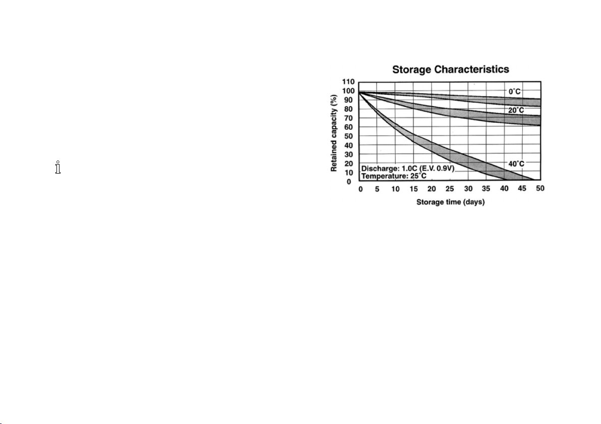
4.2.1StorageCharacteristics
4.2.2StorageT emperature
Essentiallyallrechargeablebatterycellsgraduallydischarge
overtimewhethertheyareusedornot.Thiscapacitylossis
typicallyduetoslowparasiticreactionsoccurringwithinthe
cell.Assuch,thelossrate(self-dischargerate)isafunction
ofthecellchemistryandthetemperatureenvironment
experiencedbythecell.Duetothetemperaturesensitivity
oftheself-dischargereaction,relativelysmalldifferencesin
storagetemperaturemayresultinlargedischargeswhichare
difcultorimpossibletoreverse.Cellandbatterystorage
issuesofconcerntomostapplicationdesignersrelate
eithertothespeedwithwhichthecellslosetheircapacity
afterbeingchargedortheabilityofthecellstocharge
anddischarge“normally”afterstorageforsomeperiod
oftime.Inbothsituations,generalguidelinesdeveloped
Asalreadymentioned,theself-dischargereactionrate
increaseswithhighertemperatures.Prolongedstorage
ofthebatterymaterialdeterioratingfaster;leakage
performancewillalsodeteriorate,resultinginareduced
batterylifetime.Itisrecommendedthat,forlongstorage,
batteriesshouldbekeptatroomtemperatureorbelow
(0-30°Cor32–86°F).
4.2.3StorageTime
Asthebatterylosesenergyduringstorage,thevoltage
alsodrops.Ingeneral,thebatterycapacitylossdueto
self-dischargeduringstoragecanberecoveredbyrecharging.
Ifthebatteryisstoredforoversixmonths,itisadvisable
tocyclethebatteryseveraltimestoresumethebattery
1586747-C23

Invacare®Robin®
capacity.Usegoodinventorypractices(rstin,rstout)to
reducetimecellsspendinstorage.
4.2.4StorageHumidity
Leakageandrustingofmetalpartsareaccelerated
inhighhumidityenvironments,especiallythosewith
correspondinglyhightemperatures.Therecommended
humiditylevelforbatterystorageisamaximumof60%RH.
4.2.5CapacityRecovery
Innormalpractice,storedcellswillprovidefullcapacityon
therstdischargeafterremovalfromstorageandcharging
withstandardmethods.Cellsstoredforanextendedperiod
oratelevatedtemperaturesmayrequiremorethanone
cycletoattainpre-storagecapacities.Consultationwiththe
manufacturerisrecommendedifprolongedstorageand
rapidrestorationofcapacityisrequested.
24
1586747-C

Maintenance
4.3SafetyInspectionChecklist
IMPORTANT!
–Performthisinspectionevery12months.
–Thefrequencyofinspectionmustbeincreased,
iftheproductiscontinuouslyexposedtohigh
humidity,highcondensationandcorrosives
(e.g.chlorineorammoniagases),toprevent
productimpairment.
Railsystem
qCheckthatallbracketsaretightenedcorrectlytothe
ceiling/wall.Retighten,ifnecessary.
qCheckreinforcement.Ifnotpossible,doaloadtest
with1.5xratedloadfor20minutes.
qCheckandretightenendstops.
qSystemswithtrackconnections:Checkiftheconnection
hasbecomemisalignedduringuse.Re-alignifneeded.
qChecktrolleyandtraversetrolley.
qChecktrolleywheelsforsmoothmovementand
abnormalnoise.
qCheckfrictionbreakadjustmentontrolleys.Adjustif
necessary.
qDoaloadtestwithratedloadthroughtheentire
system.
qPlaceastickerwithanewdateforthenextinspection.
Railsystemwithtransitcouplingconnections:
qCheckthelockxtures:
–securetotracking
–eachclawmovesindependently
–correctlyalignedwithtrackingslots
–noobstructionstopreventcorrectfunction
–safetyplateistted.
qChecktraversetrolleymountingxtures.
qChecktrackingalignment.Re-alignifnecessary.
qFunctiontesttransitcoupling/lockxture(10times-
disableleft/rightclawx5).
qCheckthatgapbetweentrackandtransitcouplingis
max.3mm.
qFunctiontestunderload(5cycleswithSafeWorking
Load).
qCheckinlayplateistted(LandMrail).
Ceilinghoist
qChecksuspensionandcrosspin.
qChecksteelandplasticgearwheelsforwearand
damage.
Ifgearwheelsaredry,applygearwheelgrease.
qCheckloosestrapsensorandadjustifnecessary.
qCheckstrapsforwearanddamage.
qCheckguidecylinderandendstops.
qChecktheliftinghooks,screwsandpinsforwearand
damage.
qCheckthatastickerwithmaximumloadisplacedon
thehoist.
qDoafullliftingcyclewithratedload—mustbe
effortlessandwithoutjarringsound.
qPlaceastickerwithanewdatefornextinspection.
1586747-C25
Invacare®Robin®
Electricalconnections
qCheckthatallcablesareintact.
qCheckforruptureoncablesandonisolation.
qCheckmicroswitchesforclampingandmechanical
function.
qCheckthechargerfordamage/function.
qCheckhandcontrolfordamageandfunction.Make
surethatthehandcontrolisconnectedcorrectly.
qChecktheemergencystop.
qChecktheemergencylowering.
SerialNumber:
Inspection
Date:
Inspectedby:
Comments:
4.4LOLERStatement
TheUKHealthandSafetyExecutive’sLiftingOperationsand
LiftingEquipmentRegulations1998,requireanyequipment
thatisusedintheworkplacetoliftaloadbesubjectto
safetyinspectiononasixmonthlybasis.Pleaserefertothe
HSEwebsiteforguidancewww.hse.gov.uk.
Thepersonresponsiblefortheequipmentmustensure
adherencetoLOLERregulations.
261586747-C

5Troubleshooting
5.1TroubleshootingTable
SYMPTOMSPROBLEMSOLUTION
Ceilinghoistdoesnotrespondtothehand
control’sbuttonsandup/downbuttonson
theceilinghoistarenotresponding.
Ceilinghoistdoesnotrespondtothehand
control’sbuttons,butup/downbuttons
ontheceilinghoistareresponding.
Liftingstrapswillonlymovedownand
notup.
Liftingstrapswillonlymoveupandnot
down.
Ceilinghoistspeedisthesamewithand
withoutload.
Emergencystopactivated
Systemdoesnothavepowerorbattery
isdischarged
FuseisblownReplacethefuse.Referto3.8Replacing
HandcontrolnotconnectedproperlyCheckthatthehandcontrolcableis
HandcontroldefectiveReplacethehandcontrol.Referto3.3
BatterynearlydischargedChargethebatteryorusetheemergency
LoadistoohighReducetheload.Thehoistisequipped
HandcontroldefectiveReplacethehandcontrol.Referto3.3
TheloosestrapfunctionactivatedChecktheloosestrapfunction.Referto
Non-loadquickmovementfunction
activatedpermanently
Troubleshooting
Resettheemergencystop.(Refertouser
manual)
Chargethebatteryorusetheemergency
battery.Referto4.1ChargingtheBattery,
page22.
thefuse,page16.
properlypluggedintothehoist.Referto
3.3Replacingthehandcontrol,page13.
Replacingthehandcontrol,page13.
battery.Referto4.1ChargingtheBattery,
page22.
withanover-currentsafetysystem.
Replacingthehandcontrol,page13.
5.3CheckingLooseStrapFunction,page
29.
Checkthequickmovementswitch.Refer
to5.4CheckingTwinSpeedFunctionality,
page29.
1586747-C
27

Invacare®Robin®
SYMPTOMSPROBLEMSOLUTION
LiftinghooksdonotturnfreelyenoughCleanthehooksorreplacethestraps. Liftingstrapsaretwistedanddonot
straightenout.
Ceilinghoistdoesnottraversetherails.
StrapsarefrayedReplacethestraps.Referto3.5Replacing
RailsrequireserviceorcleaningInspecttherailsystem
Drivingwheelswornordamaged(Robin®
Moveronly)
HandcontrolisdefectiveReplacethehandcontrol.
Ceilinghoistemitsexcessivenoisewhen
Bearings,gearwheelsormotordefectiveReplacethehoist.
activated.
CeilinghoistwillnotchargeSystemhasnopower
NoindicatorlightonhoistSystemdoesnothavepowerorbatteryis
discharged.
Theemergencystrapdoesnotturnhoist
Hoistrequiresservice.
off
Theemergencystrapdoesnotlowerthe
Hoistrequiresservice.
hoist.
StrapandHookAssemblies,page13.
Adjustdrivingwheels.
Placethehandcontrolinthecharging
stationandrechargetheceilinghoist
Checkthatthepowersupplyisswitched
onandconnectedtothechargingstation.
Checkthattheceilinghoisthaspower
supplyandthatthebatteryisrecharged.
Checkthatthepowersupplyisswitched
onandconnectedtothechargingstation.
Placethehandcontrolinthecharging
stationandrechargetheceilinghoist.
ContactanInvacarerepresentativefor
repair.
ContactanInvacarerepresentativefor
repair.
Ifproblemsarenotremediedbythesuggestedmeans,contactanInvacarerepresentative.
281586747-C

Troubleshooting
5.2Indicatorlightandaudiosignal
Hoist
Status
Off/Standby
Hoisttraversing
(Robin®Moveronly)
Hoistinuse
(Up/Down)
LowbatteryBlueFlashing
Theblueindicatorlightontheundersideofthehoistturns
offautomaticallyafter30seconds.
WallMountedCharger
Status
Batterynot
connected
Initializingand
analysisofbattery
FastchargeRed5min—3hours
Charged(trickle
charge)
Faultcondition
(batterydefect)
IndicatorlightAudiosignal
Off
Blue
Indicatorlight
Yellow
Yellow12–14seconds
Green
Alternatingred
andgreen
No
No
Yes
Duration
n/a
n/a
n/a
5.3CheckingLooseStrapFunction
Acorrectlyadjustedloosestrapswitchensuresthatthe
strapsstoploweringwhentheytouchanobstruction.
1.Withtheceilinghoistremainingonthetrack,check
therearenoobstructionsundereitherstraphook.
2.Placeanobstructionunderoneofthestraphooks,then
pressandholdthedownbuttononthehandcontrol,
Expectedresult:Whenthestraphooktouchesthe
obstruction,thestrapstopslowering.
3.IfthestrapdoesNOTstoplowering,adjusttheloose
strapswitch.Refertochapter3.10AdjustingLoose
StrapSwitch,page18.
4.Repeatsteps2and3forthesecondstrap.
5.4CheckingTwinSpeedFunctionality
1.Withthehoistonthetrackandbothstrapsfreefrom
obstructions,pressandholdtheupbuttonwithno
loadapplied.
Notespeed(40mm/s)andsoundofmotor.
2.Whilstcontinuingtoholdtheupbutton,applyaloadof
atleast10kg(e.g.bypullingdownonbothstraps).
Notethespeedreduction(30mm/s)andmotorsound
change.
3.Ifthereisnospeedreduction,replacethetwinspeed
switch.Refertochapter3.11ReplacingtheTwinSpeed
Switch,page19.
1586747-C29
Invacare®Robin®
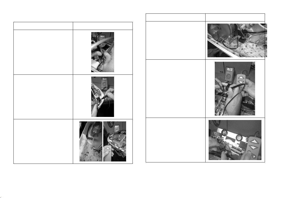
5.5TakingVoltageReadings
ReadFeedingVoltage
Takebatteryvoltagefeeding
PCB.
Expectedresult:23to29V
Takevoltagefeedingmain
switch(twomiddlepins)
Expectedresult:23to29V
Takevoltagefeedingthelift
motorwhilstpressingthe
UPorDOWNbuttononthe
handcontrol.
Expectedresult:23to29V
ReadFeedingVoltage
Takevoltagefeedingthe
hoistmoverPCB.(Robin®
Moveronly)
Expectedresult:23to29V
Takevoltagefeedingthe
copperringswhilstpressing
theLEFTorRIGHTbuttonon
thehandcontrol.(Robin®
Moveronly)
Expectedresult:23to29V
Takevoltagefeedingthe
trolleymoverPCBwhilst
pressingtheLEFTorRIGHT
buttononthehandcontrol.
(Robin®Moveronly)
Expectedresult:23to29V
301586747-C
 Loading...