

Invacare Robin Installation And Technical Manual
Invacare® Robin
TM
Installations Manual &
Technical Description

2

3
Table of Contents
1. Preface . . . . . . . . . . . . . . . . . . . . . . . . . . . . . . . . . . . . . . . . . . . . . . . . . 5
2. General . . . . . . . . . . . . . . . . . . . . . . . . . . . . . . . . . . . . . . . . . . . . . . . . .
5
2.1 Installation . . . . . . . . . . . . . . . . . . . . . . . . . . . . . . . . . . . . . . . . . . . . . . . . . . . . . . . . . . . . 5
2.2 Warranty . . . . . . . . . . . . . . . . . . . . . . . . . . . . . . . . . . . . . . . . . . . . . . . . . . . . . . . . . . . . . 5
3. The rail system EC-TrackTM . . . . . . . . . . . . . . . . . . . . . . . . . . . . . . . . 6
3.1 Mono-rail system, straight rails & curves . . . . . . . . . . . . . . . . . . . . . . . . . . . . . . . . . . . . 6
3.2 Traverse system . . . . . . . . . . . . . . . . . . . . . . . . . . . . . . . . . . . . . . . . . . . . . . . . . . . . . . . 6
3.3 Traverse systems, combinations . . . . . . . . . . . . . . . . . . . . . . . . . . . . . . . . . . . . . . . . . . . 6
3.4 Room transfer . . . . . . . . . . . . . . . . . . . . . . . . . . . . . . . . . . . . . . . . . . . . . . . . . . . . . . . . . 9
3.4.1 Room transfer with 2 hoists . . . . . . . . . . . . . . . . . . . . . . . . . . . . . . . . . . . . . . . . . . . . 9
3.4.2 Room transfer with coupling . . . . . . . . . . . . . . . . . . . . . . . . . . . . . . . . . . . . . . . . . . . . 9
4. Rails, Brackets & Accessories . . . . . . . . . . . . . . . . . . . . . . . . . . . . . . 10
4.1 Rail profiles S, M & L . . . . . . . . . . . . . . . . . . . . . . . . . . . . . . . . . . . . . . . . . . . . . . . . . . . 10
4.2 Curves 30°, 45°, 60° & 90° . . . . . . . . . . . . . . . . . . . . . . . . . . . . . . . . . . . . . . . . . . . . . . 10
4.3 Ceiling brackets, Quick . . . . . . . . . . . . . . . . . . . . . . . . . . . . . . . . . . . . . . . . . . . . . . . . . 10
4.3.1 Brackets for traverse system and side hung wall brackets . . . . . . . . . . . . . . . . . . . . 10
4.4 Ceiling brackets, standard with or without lock . . . . . . . . . . . . . . . . . . . . . . . . . . . . . 11
4.5 Shim’s . . . . . . . . . . . . . . . . . . . . . . . . . . . . . . . . . . . . . . . . . . . . . . . . . . . . . . . . . . . . . . . 11
4.6 Wall brackets, end hung . . . . . . . . . . . . . . . . . . . . . . . . . . . . . . . . . . . . . . . . . . . . . . . . 11
4.6.1 Wall brackets, side hung . . . . . . . . . . . . . . . . . . . . . . . . . . . . . . . . . . . . . . . . . . . . . . 11
4.7 Insert tubes . . . . . . . . . . . . . . . . . . . . . . . . . . . . . . . . . . . . . . . . . . . . . . . . . . . . . . . . . . 12
4.8 Wall support leg, console and wall support foot . . . . . . . . . . . . . . . . . . . . . . . . . . . . . 12
4.9 End stop . . . . . . . . . . . . . . . . . . . . . . . . . . . . . . . . . . . . . . . . . . . . . . . . . . . . . . . . . . . . . 12
4.10 Trolleys . . . . . . . . . . . . . . . . . . . . . . . . . . . . . . . . . . . . . . . . . . . . . . . . . . . . . . . . . . . . 13
4.10.1 Hoist trolley . . . . . . . . . . . . . . . . . . . . . . . . . . . . . . . . . . . . . . . . . . . . . . . . . . . . . . . 13
4.10.2 Traverse trolley . . . . . . . . . . . . . . . . . . . . . . . . . . . . . . . . . . . . . . . . . . . . . . . . . . . . 13
4.10.3 Room-to-room trolley . . . . . . . . . . . . . . . . . . . . . . . . . . . . . . . . . . . . . . . . . . . . . . . 13
4.11 Rail end plugs . . . . . . . . . . . . . . . . . . . . . . . . . . . . . . . . . . . . . . . . . . . . . . . . . . . . . . . . 13
4.12 Pendles, adjustable . . . . . . . . . . . . . . . . . . . . . . . . . . . . . . . . . . . . . . . . . . . . . . . . . . . 13
4.13 Track switch, manual . . . . . . . . . . . . . . . . . . . . . . . . . . . . . . . . . . . . . . . . . . . . . . . . . . 14
4.14 Transit coupling . . . . . . . . . . . . . . . . . . . . . . . . . . . . . . . . . . . . . . . . . . . . . . . . . . . . . . 14

4
5. Installation instructions . . . . . . . . . . . . . . . . . . . . . . . . . . . . . . . . . . . 15
5.1 General . . . . . . . . . . . . . . . . . . . . . . . . . . . . . . . . . . . . . . . . . . . . . . . . . . . . . . . . . . . . . 15
5.1.1 Milling of keyhole . . . . . . . . . . . . . . . . . . . . . . . . . . . . . . . . . . . . . . . . . . . . . . . . . . . . 15
5.2 Ceiling mounting system . . . . . . . . . . . . . . . . . . . . . . . . . . . . . . . . . . . . . . . . . . . . . . . . 16
5.2.1 Concrete ceiling . . . . . . . . . . . . . . . . . . . . . . . . . . . . . . . . . . . . . . . . . . . . . . . . . . . . . 16
5.2.2 Concrete ceiling with suspended ceiling . . . . . . . . . . . . . . . . . . . . . . . . . . . . . . . . . . 18
5.2.2.1 Mounting with pendling brackets . . . . . . . . . . . . . . . . . . . . . . . . . . . . . . . . . . . . . . 18
5.2.3 Wooden ceiling . . . . . . . . . . . . . . . . . . . . . . . . . . . . . . . . . . . . . . . . . . . . . . . . . . . . . 21
5.3 Wall installation, end hung rail . . . . . . . . . . . . . . . . . . . . . . . . . . . . . . . . . . . . . . . . . . . 23
5.3.1 Rail profile M & L . . . . . . . . . . . . . . . . . . . . . . . . . . . . . . . . . . . . . . . . . . . . . . . . . . . . 23
5.3.2 Wall bracket, side hung . . . . . . . . . . . . . . . . . . . . . . . . . . . . . . . . . . . . . . . . . . . . . . . 25
5.4 Curves . . . . . . . . . . . . . . . . . . . . . . . . . . . . . . . . . . . . . . . . . . . . . . . . . . . . . . . . . . . . . . 26
5.5 Rail coupling . . . . . . . . . . . . . . . . . . . . . . . . . . . . . . . . . . . . . . . . . . . . . . . . . . . . . . . . . 27
5.5.1 Rail coupling for profile M & L . . . . . . . . . . . . . . . . . . . . . . . . . . . . . . . . . . . . . . . . . . 27
5.5.2 Rail coupling for profile S . . . . . . . . . . . . . . . . . . . . . . . . . . . . . . . . . . . . . . . . . . . . . . 27
5.6 Wall support leg . . . . . . . . . . . . . . . . . . . . . . . . . . . . . . . . . . . . . . . . . . . . . . . . . . . . . . 28
5.7 Mounting traverse system . . . . . . . . . . . . . . . . . . . . . . . . . . . . . . . . . . . . . . . . . . . . . . . 29
5.8 Installation of rail switches . . . . . . . . . . . . . . . . . . . . . . . . . . . . . . . . . . . . . . . . . . . . . . 31
5.9 Installation of the Transit coupling . . . . . . . . . . . . . . . . . . . . . . . . . . . . . . . . . . . . . . . . 32
5.9.1 Adjustment of hole in the wall/door opening . . . . . . . . . . . . . . . . . . . . . . . . . . . . . . 32
5.9.2 Installation of transit coupling . . . . . . . . . . . . . . . . . . . . . . . . . . . . . . . . . . . . . . . . . . 33
5.9.3 Installation and connection of control button and power supply . . . . . . . . . . . . . . . 34
5.9.4 Installation of traverse system with lock fixture for transit coupling . . . . . . . . . . . . 35
5.9.5 Installation of a mono-rail rail for a coupling system . . . . . . . . . . . . . . . . . . . . . . . . 35
5.9.6 Mounting the positioning fixtures on parallel rail S-profile and M/L profiles . . . . . . 36
5.10 Mounting of Gantry with or without wheels . . . . . . . . . . . . . . . . . . . . . . . . . . . . . . . 37
6. Inspection/check of the rail system . . . . . . . . . . . . . . . . . . . . . . . . . 39
7. Technical description of the rail system EC-Track
TM
. . . . . . . . . . 39
7.1 The rail system . . . . . . . . . . . . . . . . . . . . . . . . . . . . . . . . . . . . . . . . . . . . . . . . . . . . . . . 39
7.2 Possible installations. . . . . . . . . . . . . . . . . . . . . . . . . . . . . . . . . . . . . . . . . . . . . . . . . . . . 39
7.3 Special solutions . . . . . . . . . . . . . . . . . . . . . . . . . . . . . . . . . . . . . . . . . . . . . . . . . . . . . . 39
7.4 Building dimensions and ceiling height requirements . . . . . . . . . . . . . . . . . . . . . . . . . . 40
7.5 Building dimensions for different track installations . . . . . . . . . . . . . . . . . . . . . . . . . . . 40
7.5.1 Mono-rail . . . . . . . . . . . . . . . . . . . . . . . . . . . . . . . . . . . . . . . . . . . . . . . . . . . . . . . . . . 40
7.5.2 Traverse rail system . . . . . . . . . . . . . . . . . . . . . . . . . . . . . . . . . . . . . . . . . . . . . . . . . . 41
8. Technical description of the ceiling hoist ROBINTM . . . . . . . . . . . . 42
8.1 Mechanical construction . . . . . . . . . . . . . . . . . . . . . . . . . . . . . . . . . . . . . . . . . . . . . . . . 42

5
1. Preface
This installation manual is intended as a guide when planning and carrying out the installation of a EC-TrackTM rail
system.
2. General
2.1 Installation
All installations must comply with the national rules and standards. Use only approved installation components
At every point of suspension, the roof/ceiling structure must be able to absorb a load of at least 300 kg.
Before mounting a rail system, the roof, walls, and floor must be examined carefully. In connection with the
examination, the exact materials involved in the roof and walls shall be determined. This examination must only be
carried out by a trained professional. The rail system must be mounted only by authorized personnel.
In accordance with the European standard EN 10535, the system shall be stress tested with 300 kg. This should
be done at each fixing point. This test is to be carried out as a testing of the substratum’s ability to keep the rail
system in place. This test shall be carried out by an authorised Invacare® service mechanic.
2.2 Warranty
There is a 3 year warranty on the EC-TrackTM rail system and RobinTM .
6
3. The rail system EC-TrackTM
3.1 Mono-rail system, straight rails & curves
A mono-rail system is suited for cases when a specific number of lifting places is required in the room.
A mono-rail system consists of at least one straight rail. This rail may be mounted parallel to the walls or diagonally
in the room. The rail system can be optionally extended with curves with angles of 30°, 45°, 60°
and 90°.
The rail system can be installed on the wall or the ceiling.
With a mono-rail system it is possible to hide the installation in the ceiling so that only the opening of the rail is
visible.
3.2 Traverse system
A traverse system is suited for cases when an unlimited number of lifting places is required in the room.
A traverse system consists of two parallel rails mounted on the ceiling or the wall. In each parallel rail, a traverse
trolley is inserted witch can travel the full length of the parallel rails, from end stop to end stop. Across the parallel
rails a traverse rail is mounted to the two traverse trolleys. This installation can be carried out in different ways, as
shown in the illustrations in section 3.3. With a hoist trolley inserted in the traverse rail, the hoist can travel the
full length of the traverse rail.
The system permits an unlimited number of lifting places.
3.3 Traverse systems, combinations
1. Parallel rails: S-Profile
Traverse rails: S-Profile
Under-hung traverse.
Between-hung traverse.
2. Parallel rails: S-Profile
Traverse rails: M-Profile
Under-hung traverse.
7
Partly between-hung traverse.
3. Parallel rails: M-Profile
Traverse rails: M-Profile
Under-hung traverse.
Between-hung traverse.
Partly between-hung traverse.
4. Parallel rails: S-Profile
Traverse rails: L-Profile
Under-hung traverse.
PLEASE OBSERVE! Total length of the L-Profile is max. 8 m.
8
5. Parallel rails: M-Profile
Traverse rails: L-Profile
Under-hung traverse.
PLEASE OBSERVE! Total length of the L-Profile is max. 8 m.
6. Parallel rails: L-Profile
Traverse rails: L-Profile
Under-hung traverse.
PLEASE OBSERVE! Total length of the L-Profile is max. 8 m.
Between-hung traverse.
Partly between-hung traverse.
PLEASE OBSERVE! Total length of the L-Profile is max. 8 m.

9
3.4 Room transfer
3.4.1 Room transfer with 2 hoists
Room transfer can be done by using two Robin hoists; one in each room. To ease this operation, an Invacare
room-to-room trolley is used.
Room transfer is possible in both single- or room covering installations. It is important that the rails are located
as close to the doorway as possible. When installing a room covering rail system intended for room transfer, the
traverse rail must be installed perpendicular to the wall with the doorway. The distance between the two end stop
buffers must not exceed 60 cm. To obtain the best possible result during room transfer, there must be a minimum
distance of 185 cm between the floor and the underside of the hoist. This must be kept in mind during installation
of the rail system.
3.4.2 Room transfer with coupling
As an alternative the room transfer can be achieved (remove by) an installated transit coupling.
The coupling can be used to connect either two traverse systems or one traverse system and one mono-rail
system.
The coupling is operated electrically by a control button mounted on the wall.
The coupling is delivered with a standard length of 800 mm.
For further information see section 4.14 and 5.9.
10
4. Rails, Brackets & Accessories
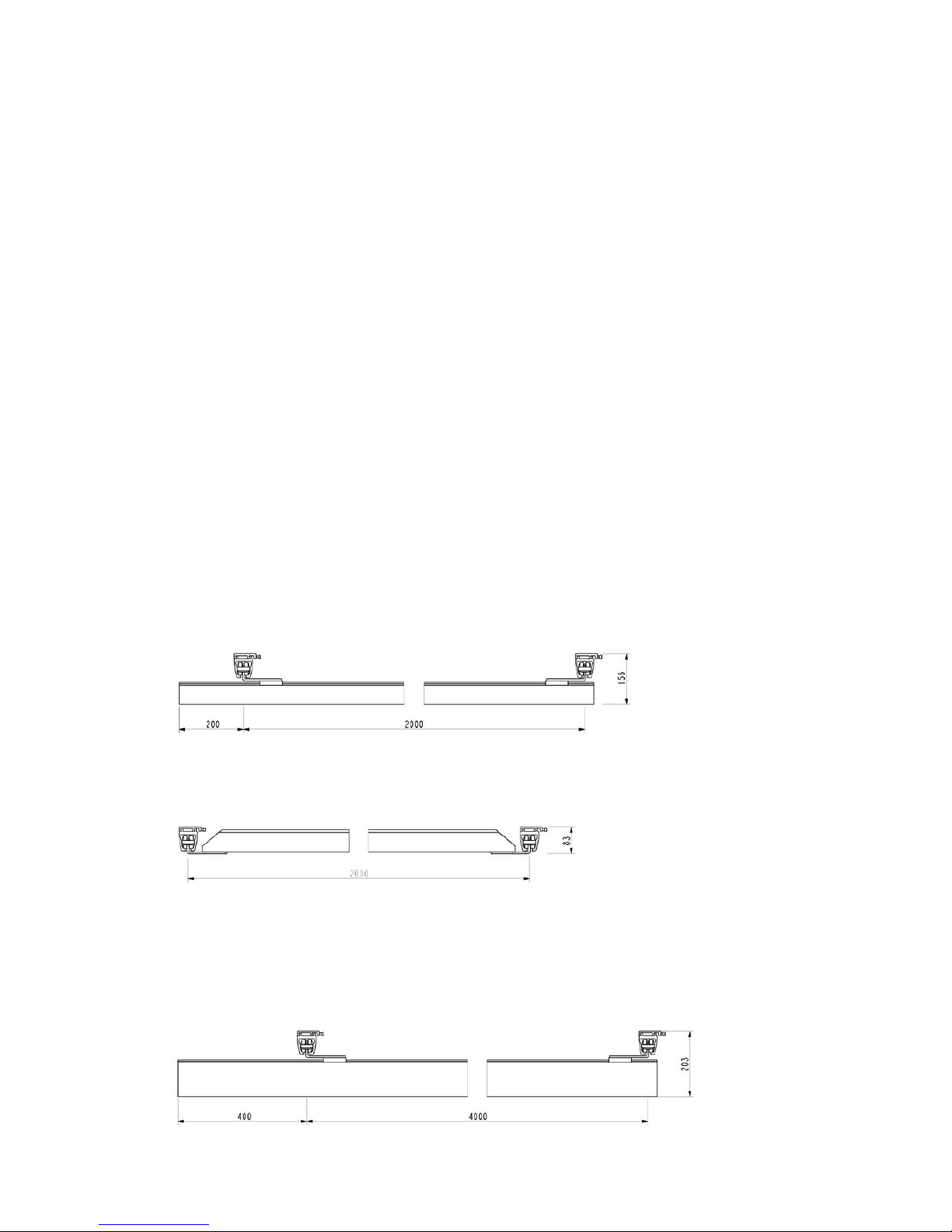
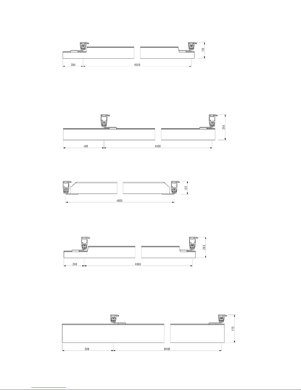
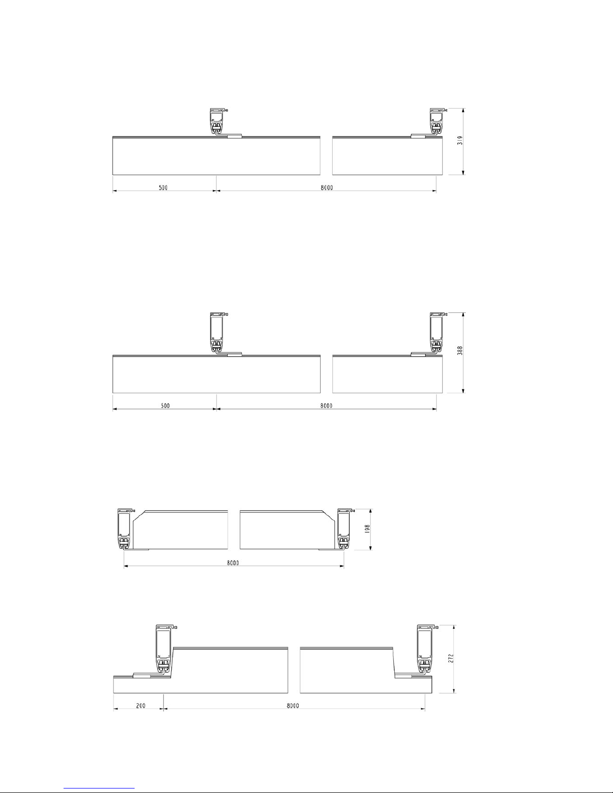
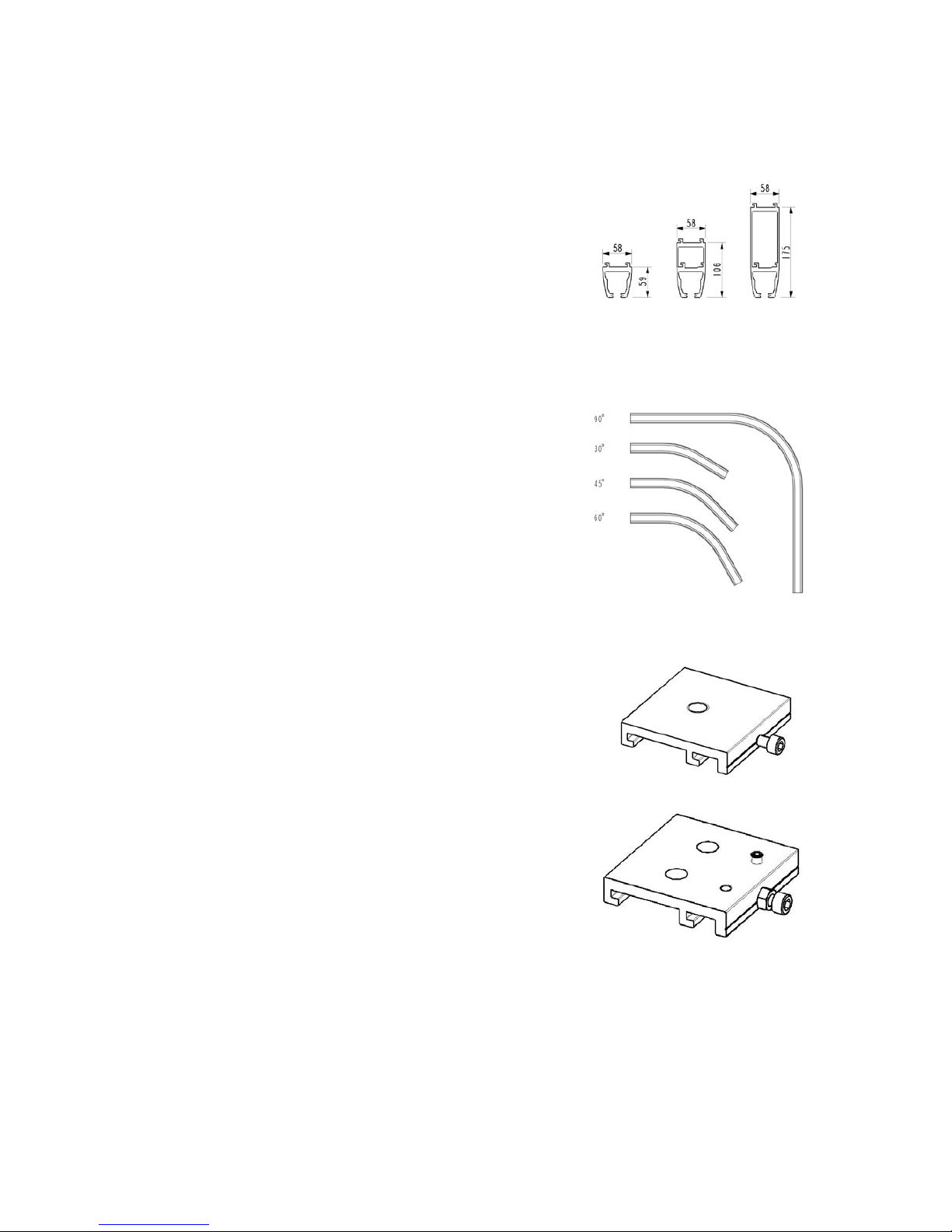
4.1 Rail profiles S, M & L
All rails are available in white or as anodized in natural.
Rail profile S is available in length of max 8 meters (white only 7.8 meters).
Max. width of span is 2 m, without support.
Rail profile M is available in length of max. 8 meters (white only 7.8 meters).
Max. width of span is 4 m, without support.
Rail profile L is available in length of max. 8 meters (white only 7.8 meters).
Max. width of span is 8 m, without support.
4.2 Curves 30°, 45°, 60° & 90°
All curves have a radius of 400 mm.
All curves are supplied as right or left curves, either white or
anodized in natural. Characteristics for right and left, see section 5.4.
Rail profile S with 90° angle. 0.6 m straight rail and 0.6 m of straight rail.
Rail profile S with 60° angle. 0.2 m straight rail and 0.2 m of straight rail.
Rail profile S with 45° angle. 0.2 m straight rail and 0.2 m of straight rail.
Rail profile S with 30° angle. 0.2 m straight rail and 0.2 m of straight rail.
4.3 Ceiling brackets, Quick
Ceiling brackets with hidden fixing parts.
Outer dimensions of bracket (70x68 ), (120x68) and (30x68) x 14 mm.
Used for ceiling installation of single-rail and traverse systems.
(70x68) ordinary ceiling suspension,
(120x68) rail coupling,
(30x68) curves.
To be installed as described in the installation instructions.
4.3.1 Brackets for traverse system and side hung wall brackets
Traverse bracket are used in connection with the assembly of a traverse
system.
The bracket is mounted beneath the traverse trolley, at the underhung
and partly between-hung traverse assembly.
The bracket is also used for side hung installation.
S-profil M-profil L-profil
11
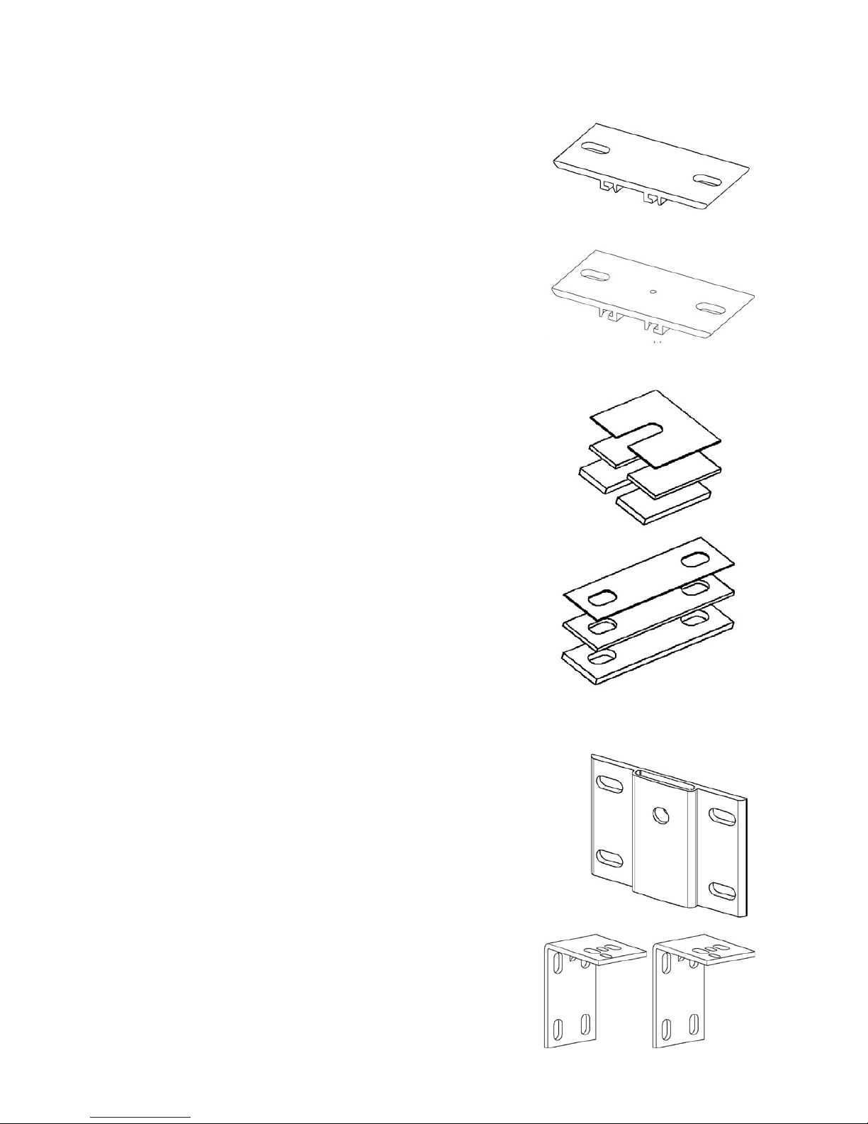
4.4 Ceiling brackets, standard with or without lock
Ceiling brackets with visible fixing parts.
Outer dimensions of bracket (70x146), (120x146 ) and (30x146) x 14 mm.
Used for ceiling installation of single-rail and traverse systems.
(70x146) ordinary ceiling suspension,
(120x146) rail coupling,
(30x146) curved rails.
To be installed as described in the installation instructions.
Ceiling bracket, standard with lock screw.
Ceiling bracket with lock screw measuring (70x146).
Used for ceiling installation, with min. 1 per straight rail.
This ensures that the rail is not displaced after installation.
To be installed as described in the installation instructions.
4.5 Shim’s
Shim for ceiling bracket:
Available in the following dimensions for ceiling bracket, quick:
Width 30, 70, and 120 mm
• 1 mm thick
• 3 mm thick
• 5 mm thick
Available in the following dimensions for ceiling bracket, standard:
Width 30, 70, and 120 mm
• 1 mm thick
• 3 mm thick
• 5 mm thick
To be used in installations to compensate for possible differences of
the height in the roof/ceiling structure.
The shim’s are supplied in white or anodized in natural.
4.6 Wall brackets, end hung
The wall brackets are used when mounting rails to a wall.
Can be used when the walls have sufficiently high carrying capacity when
mounting straight and diagonally to a wall.
To be used with insert tubes and console.
To be installed as described in the installation instructions, section 5.3.
The wall brackets are supplied in white or anodized in natural.
4.6.1 Wall brackets, side hung
To be used when installing with side hung brackets.
Can be applied if the wall has sufficient strength.
The bracket can be supplied in both grey and white.
To be installed as described in the installation instructions, section 5.3.
12
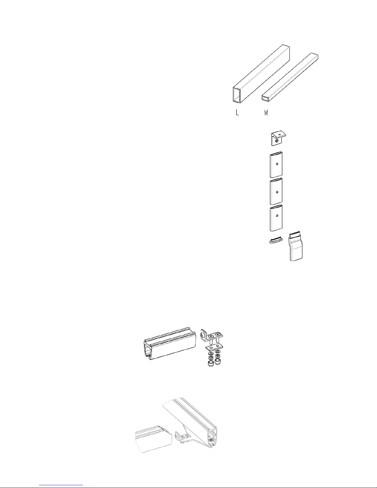
4.7 Insert tubes
To be used when mounting M or L rail end hunged to wall, when
coupling two rails, or when mounting rails diagonally in a room.
Insert tube for rail profile M is supplied in standard length of 800 mm.
Insert tube for rail profile L is supplied in standard length of 1000 mm.
Insert tube is supplied in white or anodized in natural.
Insert tube is supplied in arrange for the particular mounting situation.
4.8 Wall support leg, console and wall support foot
Wall support leg
Wall support leg are supplied in the lengths of 2600 mm and 3000 mm.
To be used if the wall does not have sufficient carrying capacity
when mounting the rail to the wall.
May be used for the mono rail systems as well as the traverse systems.
To be installed with console and support as illustrated in the installation
instructions.
Console
To be used along with wall support, as the part which the rail is mounted onto.
The console is also used together with the end hung wall bracket when
mounting straight or diagonal.
Wall support foot
Low foot.
To be used in rooms without skirting along the floor.
High foot.
To be used in a room where there is skirting board pan along the floor.
4.9 End stop
The end stop is mounted at all rail outlets, which ensures that the trolleys do not leave the rail system.
When the end stop is mounted, the rubber plug is to face towards the trolley.
When the traverse system is between-hung, the traverse rails end stop is to be mounted in the traverse trolley.
Console
Floor support
Foot
13
If the rails are mounted to a wall, the end stop is to be placed
so far into the rail that the hoist does not hit the wall
(see installation instructions).
In some countries/local areas there is a demand for double
securing of the end stops. Such extra securing can be acheived
by installing one of the following:
• Bufab MRX M5x16mm thread forming screw 10mm from
each end of the rail, 25mm from the rail underside
(the screw can be installed in a pre-drilled hole Ø4,3mm).
or
• Bufab R6B Ø6,3x22mm thread forming screw 10mm from
each end of the rail, 18mm from the rail underside.
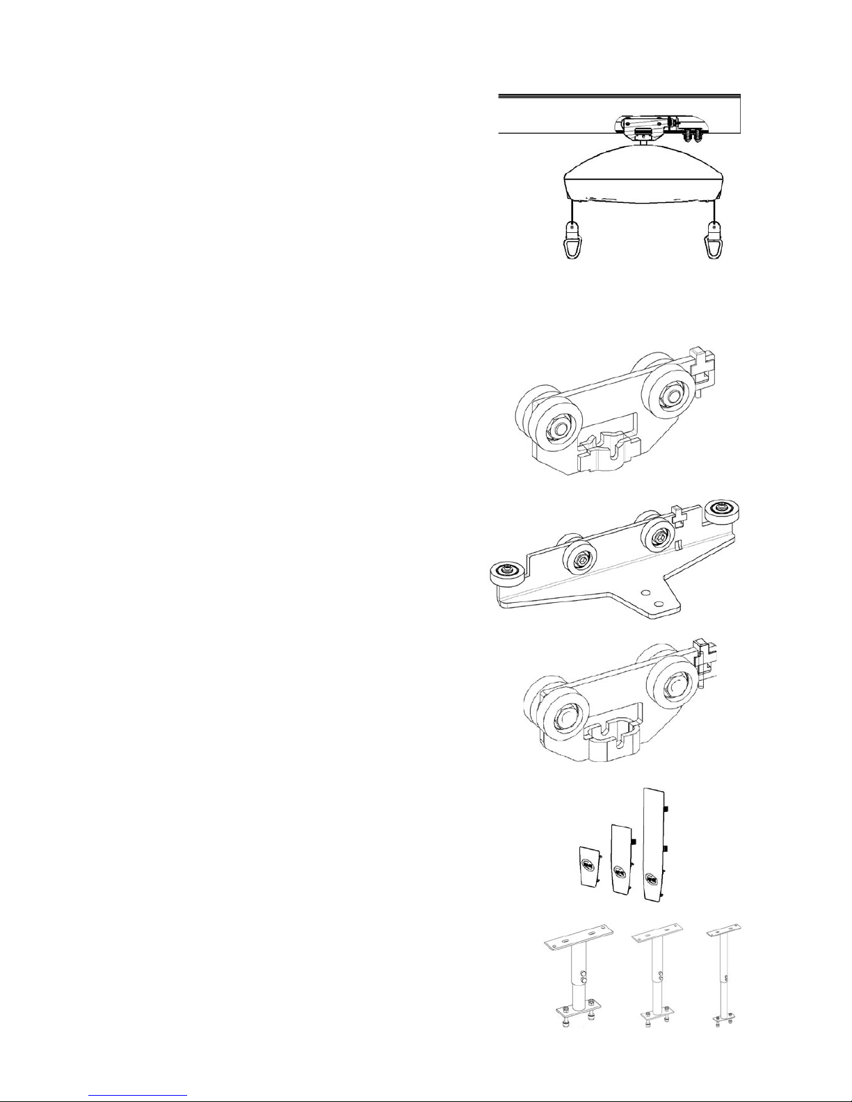
4.10 Trolleys
4.10.1 Hoist trolley
The hoist trolley is used for individual mono rail systems
as well as traverse systems.
The hoist trolley is used when a RobinTM ceiling hoist is to
be mounted in a EC-Track system.
Hoist trolleys are supplied in white or grey.
4.10.2 Traverse trolley
The traverse trolley is used when mounting a traverse system.
For a traverse system, 2 traverse trolleys are always used.
Traverse trolleys are supplied in white or grey.
4.10.3 Room-to-room trolley
The room-to-room trolley is used in EC-Track where transfer from
one room to another is required, typically through a doorway.
Room-to -room trolleys are supplied in white or grey.
4.11 Rail end plugs
Rail end plugs are supplied for rail profiles of 3 sizes,
as well as white or grey.
To be used at the closure of both ends of all rails.
Mounting: Press into the rail profile after the rail system
is mounted.
4.12 Pendles, adjustable
The pendles will be delivered with an adjustable interval of 20-30 cm,
28-46 cm, or 44-74 cm. All white coloured only.
Pendles are applied if there is a need for installing a lower rail system
than the original ceiling level. Can be used in hidden installation as well
as visible installations.
Must be installed as described in installation manual.
14
4.13 Track switch, manual
The rail switch is manually operated and is installed with a standard ceiling bracket.
The rail switch is used in combination with a ceiling installed single rail system with
S-profile, where a change in direction is required during movement of the patient.
This is installed as described in section 5.8.
Track switches are supplied in white or grey.
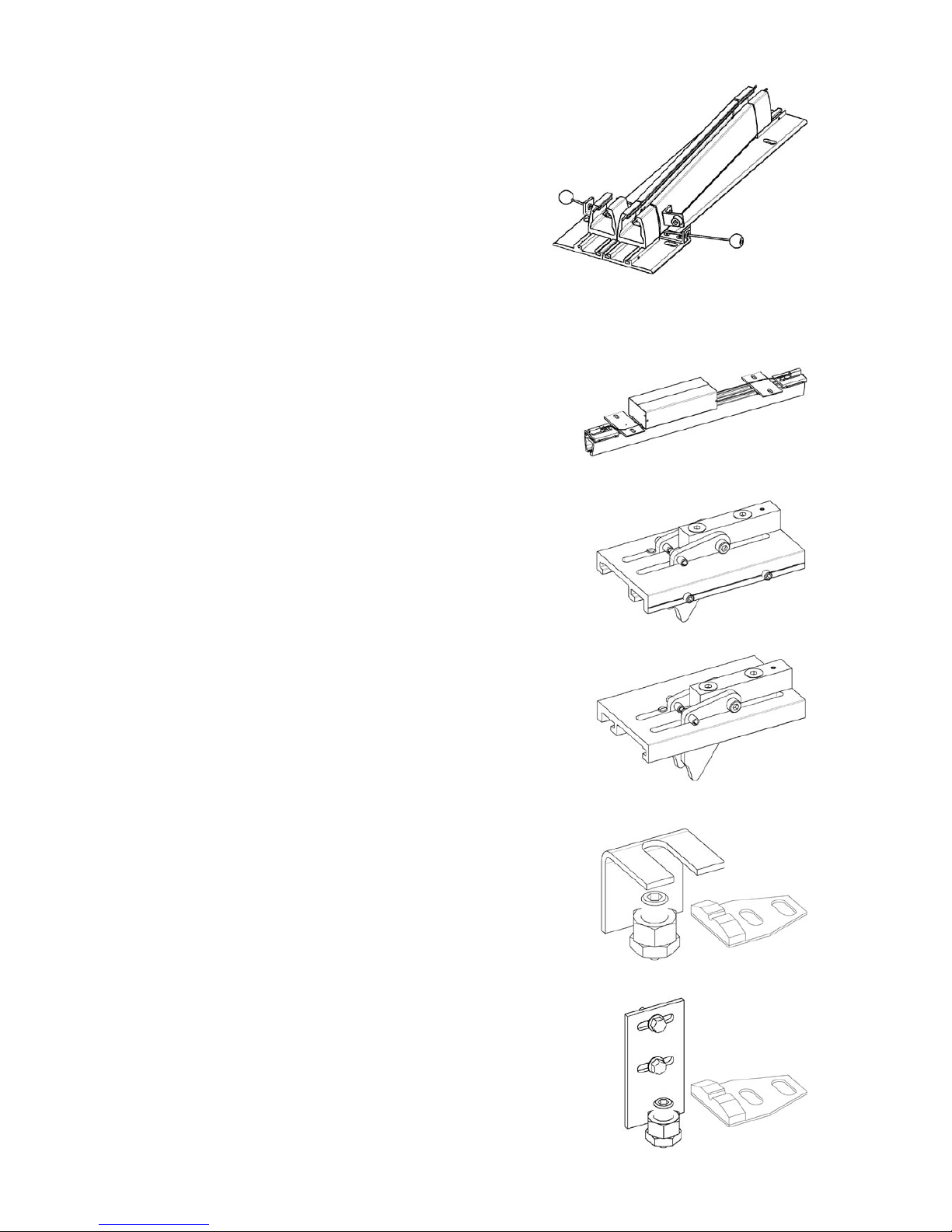
4.14 Transit coupling
The transit coupling is operated electrically and mounted with pendles in the
ceiling on both sides of the wall; it has a standard length of 800 mm.
The coupling is used for movement of a patient from one room to another.
The coupling can be used in traverse systems with S-, M,- and L-rails, and in a
mono-rail system with only S-profile rails.
The installation of the coupling is described in the Installation manual
section 5.9.
Control button (for the wall), and a transformer is enclosed, when delivered.
The coupling is available in white or grey.
Coupling lock fixture for rail profile S, to be mounted on the
traverse profile in the end that is coupled.
It is mounted to ensure that the traverse rail and coupling are locked
and connected correctly before room transfer can be done.
Installed as described in the Installation manual section 5.9.
Available in white or grey.
Coupling lock fixtures for traverse profile M/L.
To be mounted on the traverse profile in the end that is coupled,
it is mounted to ensure that the traverse rail and coupling are locked
and connected correctly before room transfer can be carried out.
Installed as described in section 5.9 Installation instructions.
Available in white or grey.
Coupling positioning fixtures for parallel rail S-profile
To be mounted on the parallel rail, close to the coupling, to position
the traverse rail correctly in proportion to the coupling.
Installed as described in section 5.9 Installation instructions.
Available in white or grey.
Coupling positioning fixtures for parallel rail M/L-profile
To be mounted on the parallel rail, close to the coupling, to position the
traverse rail correctly in proportion to the coupling.
Installed as described in section 5.9 Installation instructions.
Available in white or grey.
 Loading...