

Invacare REM 41 Remote User Manual
Invacare® REM 41
Tray/centre joystic
k
Remote
User manual
Yes, You Can.®
2
How can you get in touch with Invacare®?
If you have any questions or need support, please contact your authorised Invacare® Dealer, who has the
necessary know-how and equipment plus the special knowledge concerning your Invacare® product, and
can offer you all-round satisfactory service. Should you wish to contact Invacare® directly, you can reach us
in Europe at the following addresses and phone numbers.
Invacare Austria GmbH
Herzog Odilostrasse 101
A-5310 Mondsee
Austria
: +43 6232 5 53 50
Fax: +43 6232 5 53 54
@: info@invacare-austria.com
WWW: www.invacare.at
Invacare n.v.
Autobaan 22
B-8210 Loppem (Brugge)
Belgium
: +32 (0)50 83 10 10
Fax: +32 (0)50 83 10 11
@: belgium@invacare.com
WWW: www.invacare.be
Invacare AG
Benkenstraße 260
CH-4108 Witterswil
Switzerland
: +41 (0)61487 70 80
Fax: +41 (0)61487 70 81
@: switzerland@invacare.com
WWW: www.invacare.ch
Invacare GmbH
Alemannenstraße 10
88316 Isny
Deutschland
+49 (0)7562 70 00
Fax +49 (0)7562 7 00 66
@: kontakt@invacare.com
WWW: www.invacare.de
Invacare A/S
Sdr. Ringvej 37
DK-2605 Brøndby
Danmark
(Kundeservice): +45 (0)36 90 00 00
Fax (Kundeservice): +45 (0)36 90 00 01
@: denmark@invacare.com
WWW: www.invacare.dk
Invacare® SA
c/ Areny s/n
Polígon Industrial de Celrà
E-17460 Celrà (Girona)
ESPAÑA
: +34 (0)972 49 32 00
Fax: +34 (0)972 49 32 20
@: contactsp@invacare.com
WWW: www.invacare.es
3
Invacare® Poirier SAS
Route de St Roch
F-37230 Fondettes
France
: +33 (0)247 62 64 66
Fax: +33 (0)247 42 12 24
@: contactfr@invacare.com
WWW: www.invacare.fr
Invacare® Ltd
Pencoed Technology Park
Pencoed
Bridgend CF35 5AQ
United Kingdom
(Customer services): +44 (0)1656 77 62 22
Fax (Customer services): +44 (0)1656 77 62 20
@: uk@invacare.com
WWW: www.invacare.co.uk
Invacare Mecc San s.r.l.
Via dei Pini, 62
I - 36016 Thiene (VI)
ITALIA
: +39 0445 38 00 59
Fax: +39 0445 38 00 34
@: italia@invacare.com
WWW: www.invacare.it
Invacare Ireland Ltd.
Unit 5 Seatown Business Campus
Seatown Rd, Swords
County Dublin
Ireland
: +353 18 10 70 84
Fax: +353 18 10 70 85
@: ireland@invacare.com
WWW: www.invacare.ie
Invacare® AS
Grensesvingen 9
Postboks 6230
Etterstad
N-0603 Oslo
Norge
(Kundeservice): +47 (0)22 57 95 00
Fax (Kundeservice): +47 (0)22 57 95 01
@: norway@invacare.com
@: island@invacare.com
WWW: www.invacare.no
Invacare® B.V.
Celsiusstraat 46
NL-6716 BZ Ede
Nederland
: +31 (0)318 69 57 57
Fax: +31 (0)318 69 57 58
@: nederland@invacare.com
@: csede@invacare.com
WWW: www.invacare.nl
Invacare Lda
Rua Estrada Velha, 949
P-4465-784 Leça do Balio
Portugal
: +351 225 10 59 46
: +351 225 10 59 47
Fax: +351 225 10 57 39
@: portugal@invacare.com
WWW: www.invacare.pt

4
Återförsäljare:
Invacare® AB
Fagerstagatan 9
S-163 91 Spånga
Sverige
Tillverkare:
Invacare® Deutschland GmbH
Kleiststraße 49
D-32457 Porta Westfalica
Deutschland
(Kundtjänst): +46 (0)8 761 70 90
Fax (Kundtjänst): +46 (0)8 761 81 08
@: sweden@invacare.com
@: finland@invacare.com
WWW: www.invacare.se
MÖLNDAL
: +46 (0)31 86 36 00
Fax: +46 (0)31 86 36 06
@: ginvacare@invacare.com
LANDSKRONA
: +46 (0)418 2 85 40
Fax: +46 (0)418 1 80 89
@: linvacare@invacare.com
OSKARSHAMN
: +46 (0)491 1 01 40
Fax: +46 (0)491 1 01 80
@: oinvacare@invacare.com
Eastern
european
countries
European Distributor
Organisation (EDO)
Kleiststraße 49
D-32457 Porta Westfalica
Deutschland
+49 (0)5731 75 45 40
Fax +49 (0)5731 75 45 41
@: edo@invacare.com
WWW: www.invacare.de

5
Table of Contents
Chapter Page
1 Introduction .....................................................................................7
1.1 Important symbols in this manual .........................................................................................7
2 Fittings .............................................................................................9
2.1 The remote............................................................................................................................9
2.2 Operating and control panel ...............................................................................................11
2.2.1 Vehicle functions..............................................................................................................11
2.2.2 Electronic adjustment ......................................................................................................12
3 Quick reference .............................................................................12
4 Displays on the operating and control panel..............................15
4.1 Battery charging display .....................................................................................................15
4.2 Drive mode and drive mode display ...................................................................................16
4.3 Displaying status information..............................................................................................17
5 Switches on the operating and control panel.............................18
5.1 ON/OFF button ...................................................................................................................18
5.2 Activating / deactivating the immobilizer.............................................................................19
5.3 Drive mode switching..........................................................................................................20
5.4 Indicators ............................................................................................................................21
5.5 Hazard lamps......................................................................................................................22
5.6 Lighting ...............................................................................................................................23
5.7 Horn 24
6 Joystick ..........................................................................................25
6.1 General info ........................................................................................................................25
6.2 Driving safety ......................................................................................................................25
6.3 Steering and driving commands .........................................................................................26

6
7 Connection sockets ......................................................................28
7.1 Charging socket..................................................................................................................28
7.2 Programming socket...........................................................................................................29
7.3 Connection socket for BUS cable (supply cable) ...............................................................29
8 Operation of electrically adjustable options...............................30
9 Electrical seat, backrest and legrest adjustment with the remote
control ............................................................................................34
10 Battery, charging and maintenance.............................................35
10.1 Notes on charging batteries..............................................................................................35
10.2 Charging the batteries ......................................................................................................36
10.3 Battery maintenance.........................................................................................................37
11 Cleaning the remote......................................................................37
12 Troubleshooting ............................................................................38
13 Error code list ................................................................................41
7
1 Introduction
This supplementary operating manual is intended to acquaint you with the functions of the "Action
Control System" remote for the table or centre joystick.
The operating manual contains a description of:
• control elements
• display elements
• control functions
and information about caring for the remote.
CAUTION!
This operating manual is only valid in connection with the operating manual supplied with
your mobility aid.
• You should read the operating manual supplied with your mobility aid thoroughly.
• Damaged and errors caused by the nonobservance of the operating manual are excluded
from the guarantee.
• Please contact your INVACARE specialist dealer if you have questions or if anything is
unclear.
1.1 Important symbols in this manual
CAUTION!
This symbol warns you of danger!
• Always follow the instructions to avoid injury to the user or damage to the product!

8
NOTE:
This symbol identifies general information which is intended to simplify working with your product
and which refers to special functions.
9
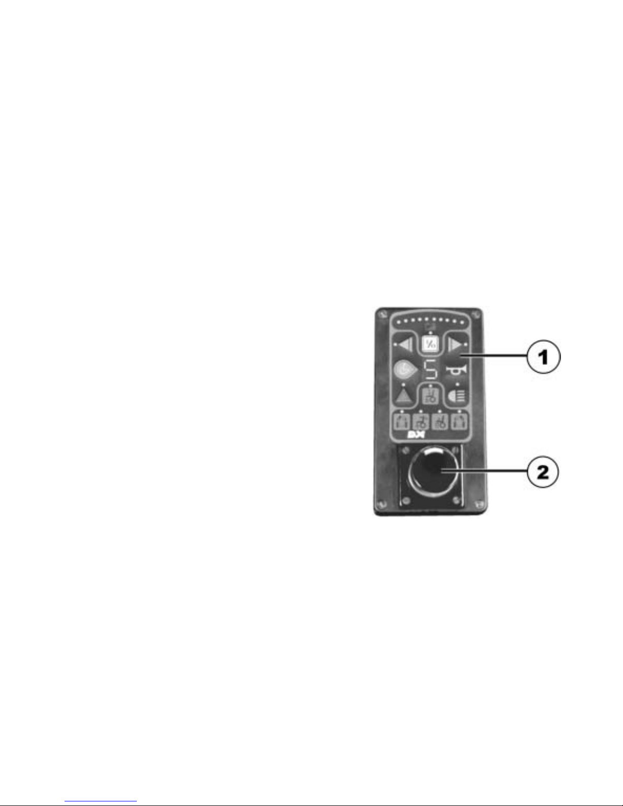
2 Fittings
2.1 The remote
The remote is used for checking and controlling the mobility aid functions.
It is divided into the following sections (Figures 1 & 2):
• Operating and control panel (1)
• Drive lever (2)
• Charging socket (3)
• Socket for BUS cable(4)
• Socket for programming device (5)
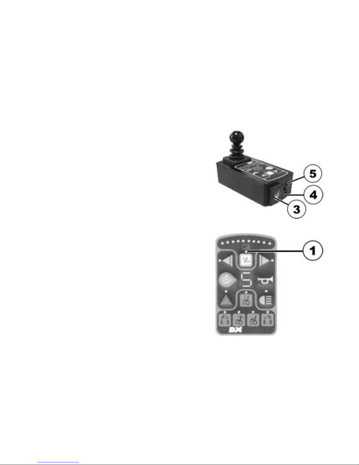
Fig. 1: Remote area
10
Fig. 2:
In addition to checking and control, the ACS remote
(ACS = Action Control System) carries out the following
monitoring functions:
• monitoring of drive system
• monitoring of power supply
If there is a fault or an electrical equipment component
breaks down, the fault will be shown by the status
display (1) blinking.
Operating and control panel
11
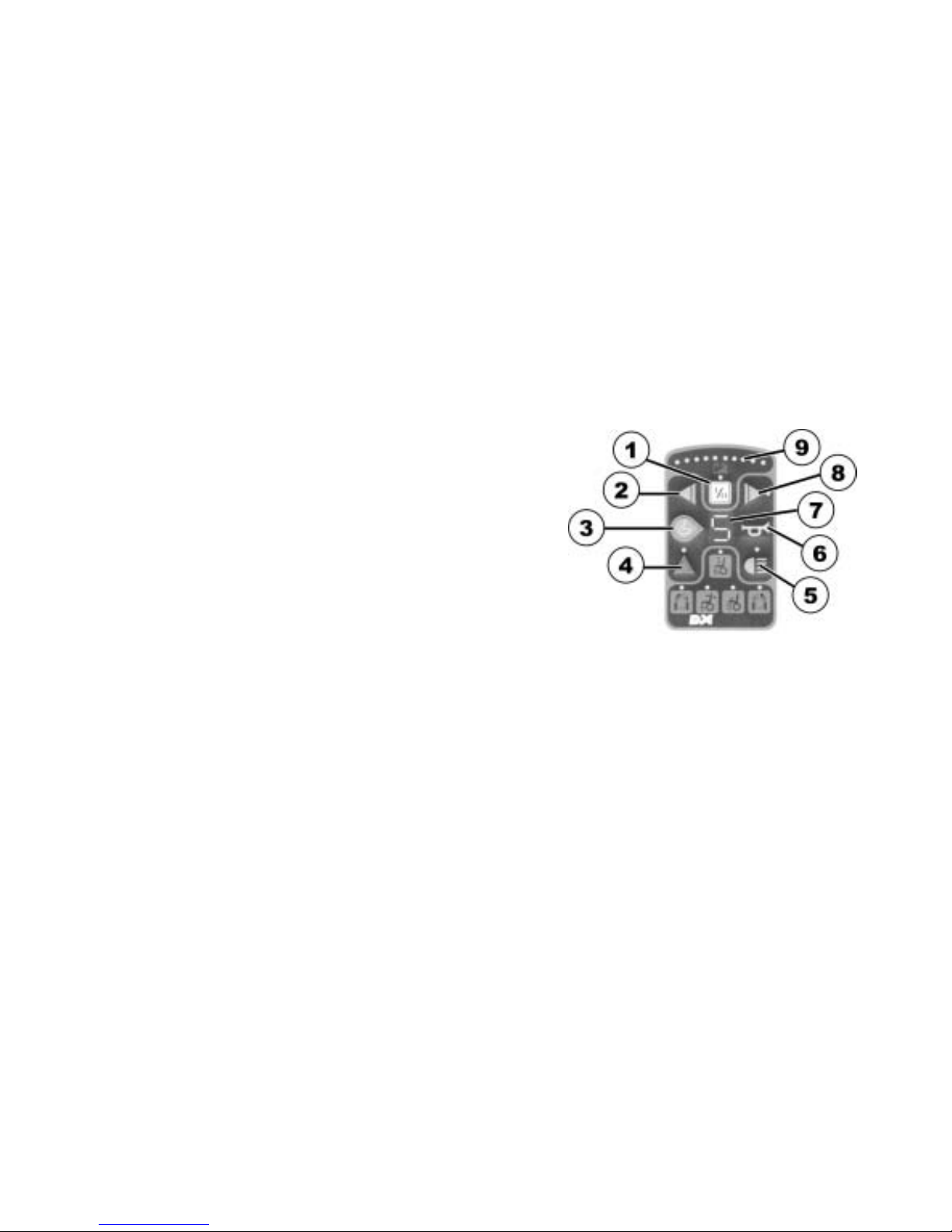
2.2 Operating and control panel
2.2.1 Vehicle functions
1) ON/OFF
2) Left-hand indicator
3) Switching drive mode
4) Hazard lamps
5) Light
6) Signal horn
7) Drive mode display
8) Right-hand indicator
9) Battery charge display
12
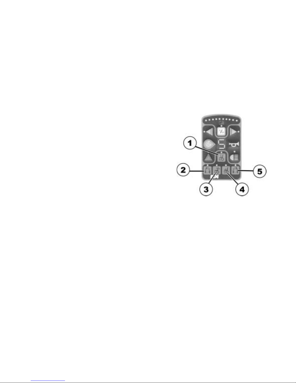
2.2.2 Electronic adjustment
1) Lifter
2) Legrest, left
3) Backrest adjustment
4) Seat inclination adjustment
5) Legrest, right
3 Quick reference
• Unlock the remote lock.
13
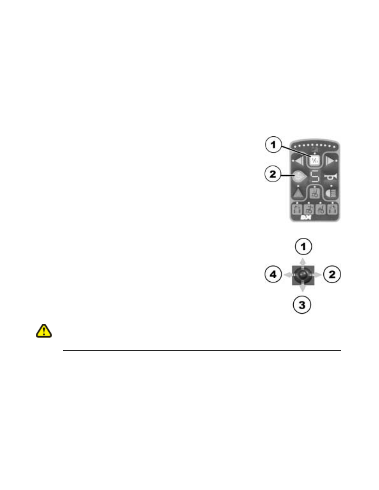
• Switch the remote on with the ON/OFF (1) button.
• Use the drive mode switching (2) to select the required drive
level.
Operating panel
• Use the drive lever to make all steering and driving commands:
1) forward
2) right
3) backward
4) left
Steering and driving
CAUTION!
Tipping hazard
• Avoid sudden or jerky drive lever movements.

14
15
4 Displays on the operating and control panel
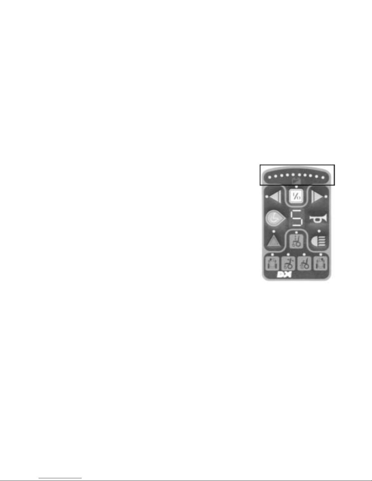
4.1 Battery charging display
The battery charging display shows you the current battery charging
condition.
It is divided into 10 colour-coded diodes (3 x red, 4 x yellow, 3x
green).
If an individual diode goes out, this shows the reduced battery
charging condition and therefore the reducing driving range of the
mobility device.
Display meanings:
All diodes illuminate
full driving range = batteries completely charged
three red diodes illuminate
reduced driving range = recharge batteries at end of journey
three red diodes blinking
extremely low driving range = recharge batteries as soon as possible
 Loading...