

Invacare Rea Dahlia 30, Rea Dahlia 45 Service Manual
Rea®Dahlia®30/45
enManualwheelchairpassive
ServiceManual
DEALER:Keepthismanual.
TheproceduresinthismanualMUSTbeperformedbyaqualied
technician.
Dahlia 4 5

©2017Invacare®Corporation
Allrightsreserved.Republication,duplicationormodicationinwholeorinpartisprohibitedwithoutpriorwritten
permissionfromInvacare.Trademarksareidentiedby™and®.AlltrademarksareownedbyorlicensedtoInvacare
Corporationoritssubsidiariesunlessotherwisenoted.

Contents
1General.........................................4
1.1Introduction..................................4
1.2Deliverycheck.................................4
1.3Customerservice...............................4
2Assembly........................................5
2.1Changingthebackresttubes......................5
2.2Placingthewires...............................6
2.2.1Wireswithbackrestplate......................6
2.2.2Wireswithtensionadjustablebackrest............6
2.3Tiltscalebackrest..............................7
2.4Tiltscaleseat.................................7
2.5MountingtheDripstand.........................7
2.6Mountingtheattachmentfortabletray..............8
2.7Mountingthetabletray.........................8
2.8Mountingthehalftray..........................8
2.9Mountingtheposturebelt.......................8
2.10Mountingtherearwheels.......................8
2.11Mountingtheusermaneuveredtilt................9
2.12Reducingtiltand/orbackrestrecline..............10
2.12.1Mountingofthetilt/reclinereductionbushing.....11
2.12.2Mountingtheseattiltreductionblock...........11
2.13Repositioningthebackrestjoint...................11
2.14Mountingthelegrestattachmentforhighposition.....11
2.15Mountingtheaccessorytray.....................12
2.16Washsealingkit..............................12
2.17Mountingthekerblever........................13
2.18Mountingantitipper...........................13
2.19Mountingthedrumbrake.......................13
2.19.1Drumbrakefor16”wheels...................13
2.19.2Drumbrakefor22–24”......................14
2.20MountingthewirefortheOnearmbrake...........15
2.21MountingOnearmbrake.......................15
2.22Mountingtheelectricaltilt......................15
2.22.1Mountingthebattery........................15
2.22.2Chargingthebattery........................16
2.22.3Mountingtheactuators......................16
2.22.4Mountingthecontrolbox.....................18
2.22.5Electricalschedule..........................20
2.23Assemblegaspiston—Backrestandseat...........21
2.23.1Assemblinggaspistontothechassis............21
2.23.2Assemblingwireforgaspiston.................21
2.24MountingtheRiggingscrew.....................21
2.25Changingtherearwheelattachment................21
2.26Mountingtheone—armdrive....................22
2.27Changingthehandrimforone—armdrive..........23
3SettingsandAdjustments............................24
3.1Backrestplate.................................24
3.1.1Heightadjustmentbackrestplate................24
3.1.2Widthadjustmentbackrestplate................24
3.2SpecialadaptationofFlex3backrest................24
3.3Tensionadjustablebackrest.......................25
3.3.1Adjustmentheight—tensionadjustablebackrest....25
3.3.2Widthadjustment—T ensionadjustablebackrest....25
3.3.3Angleadjustment—T ensionadjustablebackrest....26
3.4Positioningtheheadrest/neckresttothefront.........26
3.5Adjustingtheuseroperatedtilt....................27
3.6Backrestangle—riggingscrew....................27
3.7Armrest.....................................27
3.7.1Adjustingthearmrestheight...................27
3.7.2Adjustingthearmrest/siderestdepth.............28
3.8Adjustingtheseatdepth.........................28
3.9Adjustingtheseatwidth.........................28
3.10Rearwheelattachment.........................28
3.11Adjustingtheseatheightandbalancepointwiththe
rearwheelattachment..........................29
3.11.1Rearwheelattachment—standardposition.......29
3.11.2Turningtherearwheelattachment..............29
3.11.3Rearwheelattachmentmountedontheopposite
side.....................................30
3.11.4Rearwheelattachmentturned—oppositesides....30
3.11.5Rearwheelattachment—depthadjustment......30
3.12Castorattachment.............................30
3.12.1Castorattachment—adjustments..............30
3.13Mountingtheseatplateextension.................31
3.13.1Seatplateextensiontothefront...............31
3.13.2Seatplateextensiontotherear................31
3.13.3Seatplateextensionsidewise..................31
3.14Widthadjustment.............................32
3.15Adjustingthewidthofthelegrest.................32
3.16Centrallegrest................................32
3.16.1Adjustingtheheightofthecentrallegrest........32
3.16.2Adjustingthefootangleofthecentrallegrest.....32
3.16.3Adjustingthedepthofthecentrallegrest.........33
3.16.4Adjustingtheangleofthecentrallegrest.........33
3.17Adjustingthecalfpads.........................33
3.18Assembletheposturebeltforpositioning...........33
3.18.1Assembleposturebelttofrontattachment........33
3.18.2Assembleposturebelttorearattachment........34
3.19Adjustingthewidthoftheaccessorytray...........34
3.20Adjustingthedepthoftheaccessorytray...........34
3.21Brakeattachment.............................34
3.22Adjustingthebrakeeffect.......................35
3.22.1Userbrake—adjustment.....................36
3.22.2Drumbrake—adjustments...................36
3.22.3Footmaneuveredbrake—adjustments..........37
4Maintenance.....................................38
4.1Safetyinformation..............................38
4.2Maintenanceelectricalversion—SM...............38
4.3Flattire......................................38
4.4Cleaning.....................................38
4.5Washinganddisinfection.........................38
4.5.1Electricalversion............................38
4.6Reconditioning................................39
4.6.1Checklistforreconditioning....................41
5AfterUse........................................42
5.1Recycling.....................................42
5.2Wastedisposal................................42
6Troubleshooting...................................43
6.1Troubleshootingelectricalsystem...................43
6.2Limitationareas—Troubleshooting.................43
6.2.1Seattilt...................................43
6.2.2Seatdepth.................................44
6.2.3Backrestrecline.............................44
7T echnicalData....................................45
7.1Dimensionsandweights.........................45
7.1.1Sizeofantitipper............................46
7.2Material.....................................47
7.3Environmentalconditions........................47
7.4Electricalsystem—Modelsequippedwithelectrictilt
andbackrest.................................47
7.5Electromagneticcompliance(EMC).................47
7.6EMC-Manufacturer´sdeclaration..................48
7.7Seatheighttables..............................48

Rea®Dahlia®30/45
1General
1.1Introduction
Thisservicemanualcontainsinformationabouttechnical
adjustments,technicaldata,descriptionsofhowaccessories
arepersonallyttedandslightlymoreadvancedsettings.
Thismustbereadthoroughlybytheresponsibletechnician
orassistingpersonwhenadaptingthewheelchair.
WARNING!
Riskofinjury
Ifthesetupofthewheelchairisimproper ,itmay
notfunctionproperly .
–Changestothewheelchairshouldonlybe
carriedoutbytrainedpersonnel.
Forpre-saleanduserinformation,pleaseseethe
usermanual.Theusermanualcanbefoundon
Invacare’swebsite.
1.2Deliverycheck
Anytransportdamagemustbereportedimmediatelyto
thetransportcompany.Remembertokeepthepackaging
untilthetransportcompanyhascheckedthegoodsanda
settlementhasbeenreached.
1.3Customerservice
Forcontactdetailspleaserefertothelastpageofthis
publicationwhereyouwillndtheaddresstoyourlocal
Europeansalescompany .
4
1572308-G
Assembly
2Assembly
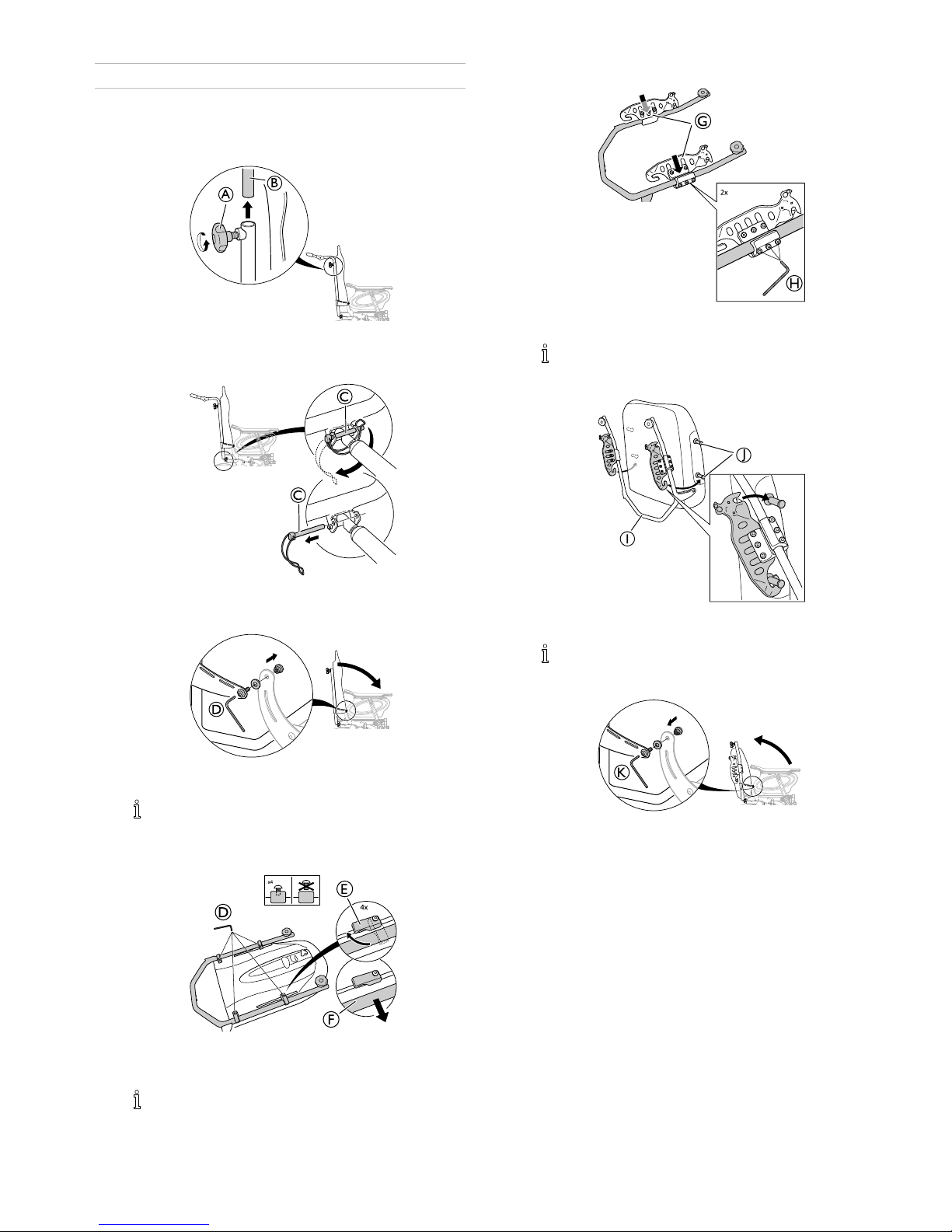
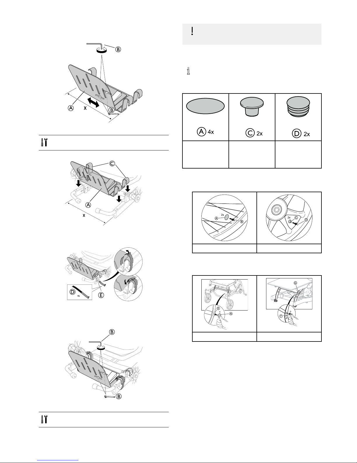
2.1Changingthebackresttubes
1.
B
ReleasetheknobAandremovethepushhandles/
pushbarintendedforthestraightbackresttubeB.
2.
C
C
ReleasethesafetyshackleCandcarefullyremovethe
safetypinfromtheattachment.
3.
LoosenandremovethescrewwasherandnutDfrom
thebackrestattachment.
Whenre-mountingthebackrest(seeinstructions
below),anewscrewmustbeused,theoldone
mustbescrapped.
4.
4x
x4
D
E
F
LoosenthefourscrewsforthebackresttubesDand
turntheattachmentsEinordertoreleasethebackrest
tubeF.
Donotremovethescrews.
5.
H
2x
G
MounttheattachmentsfortheMatrXbackrestGand
tightenthescrewsH.
Tools:5mmAllenkey
6.
2x
J
MountthebackresttubesIontheattachmentknobs
Jonthebackrest.
Startwiththelowerattachment.
7.
Re-mountthebackrestonthewheelchair ,replacethe
screwandtightenthescrew,washerandnutK(9Nm).
1572308-G5
Rea®Dahlia®30/45
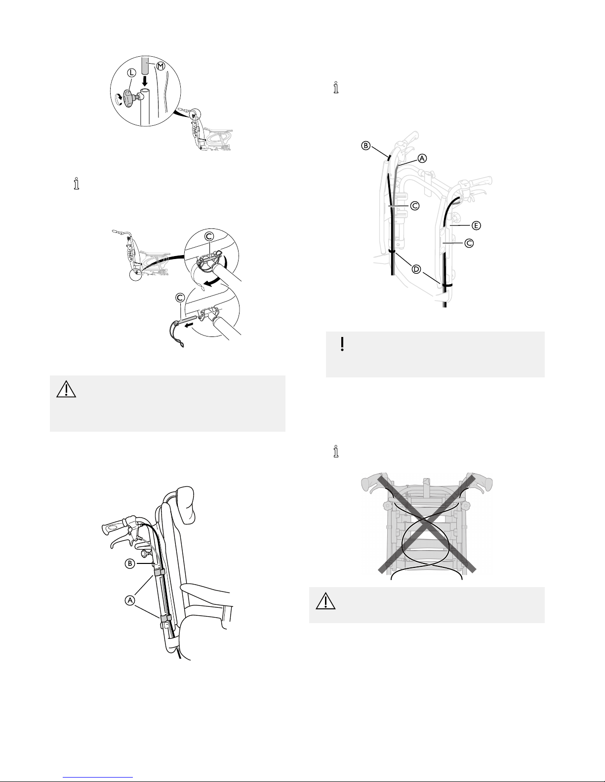
8.
L
M
Mountthepushhandles/pushbarintendedforthebent
backresttubeMandtightentheknobL.
Therearedifferentpushhandles/pushbarfor
thestraightbackresttubeandthebentbackrest
tube.
9.
C
C
Re-mountthesafetyshackleCandattachthegas
piston.
WARNING!
Safetyrisk
Thewheelchairmaycollapse
–Remembertoalwaysreinsertandfastenthe
safetypinwhenithasbeenremoved.
2.2Placingthewires
2.2.1Wireswithbackrestplate
A
B
1.ThreadthewiresontheoutsideofthebackresttubesB.
2.Placethewiresintheholders/clipsAinordertohold
theminplace.
Foldtheslackofthewiresundertheseattoget
themoutoftheway.
2.2.2Wireswithtensionadjustablebackrest
A
B
C
C
D
E
1.PlacethewiresAandBasshownonthepictureabove.
Riskofdamagetothewires
–Itisimportantthatthecableforthe
assistantbrakeAisplacedontheinsideof
thebackresttubes.
2.Placethewireforthebackrest/seatreclineBoutsideof
thebackresttubes.
3.Placebothofthewiresontheinsideofthebackrest
attachmentC.
4.AttachthewirestothebackresttubesEwiththestraps
D.
Foldtheslackofthewiresundertheseattoget
themoutoftheway.
CAUTION!
Riskofreducedbrakeeffect
–Thewiresmustnotbecrossedonthebackrest!
61572308-G
Assembly
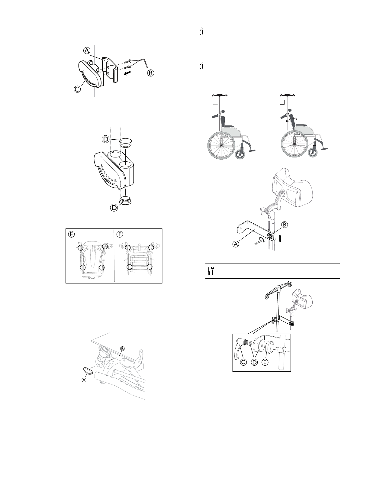
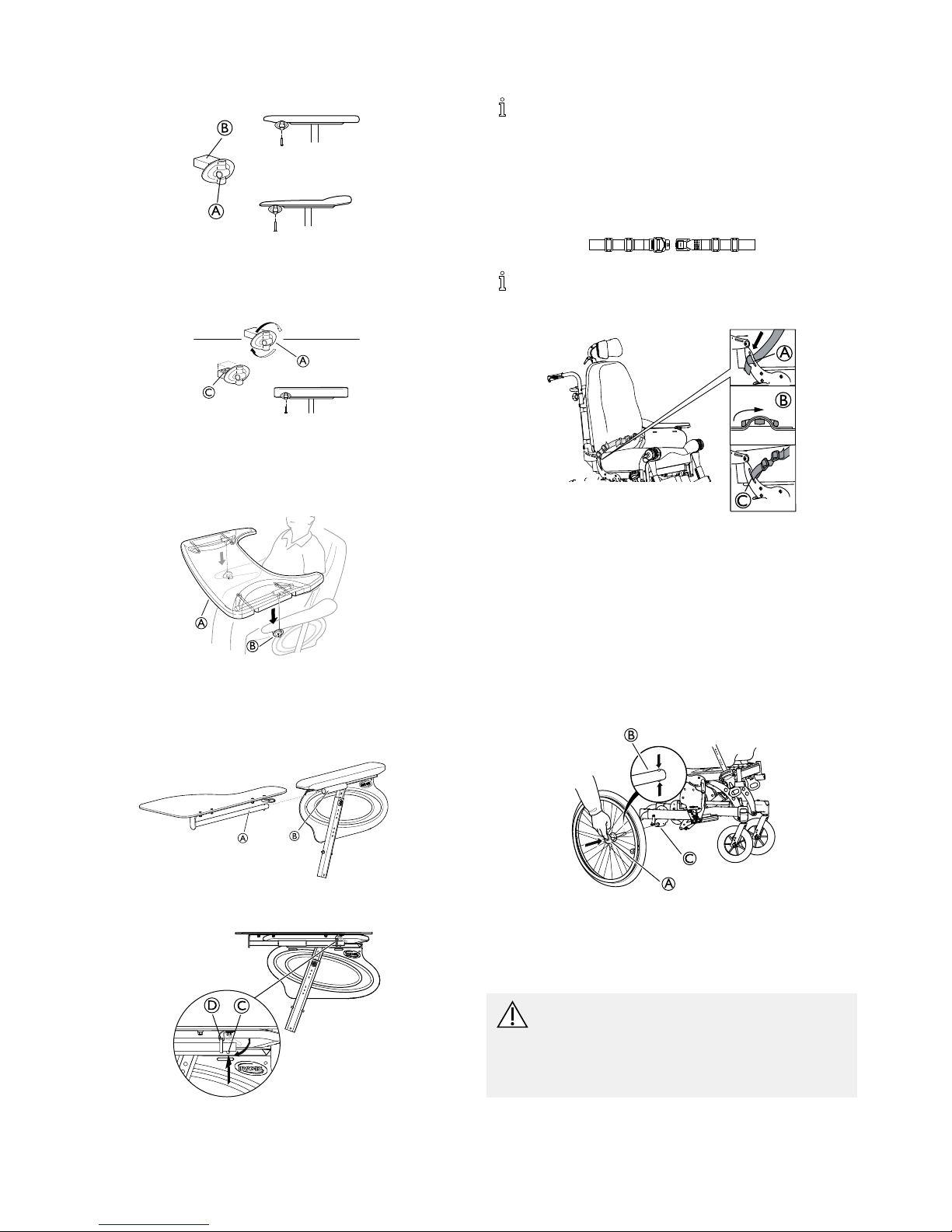
2.3Tiltscalebackrest
1.
A
B
C
AttachtheclampsAwiththetiltscaleCtothepush
bar/pushhandlesorthebackresttubesandtightenthe
screwsB.
2.
D
D
PlacetheendplugsDintheemptyholes.
3.
E F
Placethetiltscaleforthebackrestangleonthepush
bar/pushhandleoronthebackresttubesaccordingto
pictureEorFabove.
2.4Tiltscaleseat
1.
A
B
PlacethetiltscalefortheseatAontheseatframeB.
Thetiltscaleshouldbeplacedontheleftside.
2.5MountingtheDripstand
Therodofthedripstandmustalwaysbeplacedin
averticalposition,i.eina90degreeangletothe
ground,nomatterthepositionofthebackrestor
thewheelchair .
90°
90°
1.
A
B
MounttheholderforthedripstandAontheneckrest
holderandtightenthescrewB.
allenkey5mm
2.
C
D
E
MounttheleverC,thewashersDandtheholderwith
thedripstandEintheattachmentandtightenthelever .
1572308-G
7
Rea®Dahlia®30/45
2.6Mountingtheattachmentfortabletray
1.
A
B
MountthetableattachmentAwiththeattachmentpart
facingoutwards.TheplainsurfaceBoftheattachment
shouldbeplacedupwardswhenusingthetableonthe
thinarmrests.
2.
A
C
TotthetableattachmentAtothewidearmrest,turn
theattachmentaround,thepatternedsurfaceCshould
nowbefacingupwards.
2.7Mountingthetabletray
A
B
MountthetabletrayAinthetabletrayattachmentsB.
2.8Mountingthehalftray
Mountingthehalftray
A
B
1.InsertthetubeofthehalftrayAintotheattachment
Bunderthearmpad.
D
C
2.PushonthepushpinCandinserttheringDonthe
tubeA.
3.ReleasethepushpinC.
2.9Mountingtheposturebelt
Belts/harnesseswhichareCE-markedforthepurpose
ofusingonwheelchairs,canbemountedonthe
chairwithpreservedCE-marking.Thebelt/harness
shouldbettedbytheresponsibleprescriberandbe
mountedbyanexperiencedtechnician.However ,
whentransportingthewheelchairinavehicle,
Invacare’soriginalpelvicbeltmustbeusedasa
complementtothesafetybeltinthevehicle!
Theposturebeltisusedtopreventtheriskoffalling
orslidingoutofthechairandforprovidingtheuser
withagoodposture.
B
A
C
TheposturebeltCismountedonthebackrestbracketsA.
1.Threadtheposturebeltthroughthemountingonthe
chairandthenthroughthetwoplasticbucklesasshown
inpictureB.
2.Threadtheposturebeltthroughbothoftheplastic
buckles.
2.10Mountingtherearwheels
B
A
C
1.Pressandholdinthequick-releasebuttonA.
2.PlacetherearwheelaxleBintherearwheel
attachmentC.
3.Pullthewheelsoutwardstocheckthatthewheelis
securelylockedinposition.
WARNING!
Riskofinjury
–Checkthattherearwheelissecurelylockedin
position!Itshouldnotbepossibletoremove
thewheelswhenthequick-releasebuttonA
isinactivated.
81572308-G
Assembly
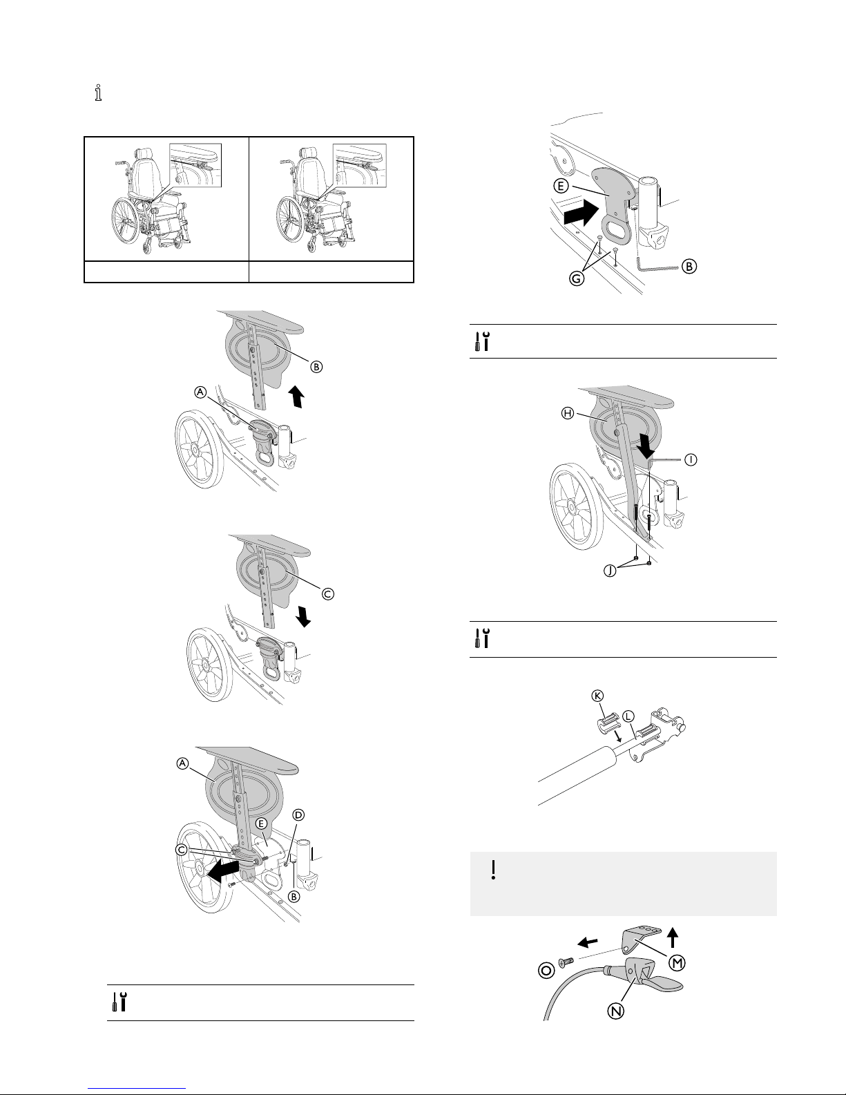
2.11Mountingtheusermaneuveredtilt
Theuseroperatedtiltisavailablewithbothaxed
armrestandwithdetachablearmrests.Theuser
operatedtiltisonlyavailableforDahlia30.
Dahlia 45
Da
hlia
45
FixedarmrestsDetachablearmrests
Detachablearmrests
A
B
1.PressandholdthequickreleasebuttonA.
2.RemovetheexistingarmrestBbypullingitupwards.
C
3.MountthenewarmrestfortheuseroperatedtiltC.
Fixedarmrests
A
B
C
D
E
1.LoosenthescrewB.
2.DragthetransportattachmentEandthearmrestA
outwards.
3.LoosenthescrewsCandthenutD.
•5mmallenkey
•10mmxedspanner
4.RemovethearmrestAandthearmrestattachment
completely.
B
G
E
5.PushthetransportattachmentEbackinplace.
6.TightenthescrewB.
5mmallenkey
7.RemovetheplasticplugsGfromthechassis.
H
J
I
8.Mountthearmrestandarmrestattachmenttubeforthe
useroperatedtiltHontheframe.
9.AttachthescrewsIandtightenthenutsJ.
•5mmallenkey
•10mmxedspanner
Detachableandxedarmrest
K
L
1.MountthetiltreductionbushingKontheseattiltgas
pistonLifneeded.
IMPORTANT
–Whenusingtheuseroperatedtilt,there
mustalwaysbetwotiltreductionbushings
mounted.
M
N
O
1572308-G9
Rea®Dahlia®30/45
1.LoosenandremovethescrewO.
2.RemovethetilthandleNfromtheattachmentM.
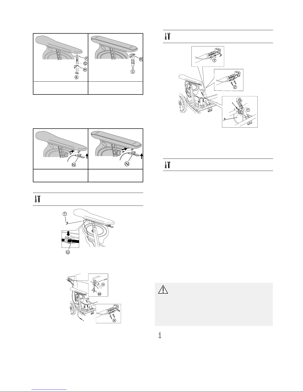
M
R
P
Q
M
S
StandardarmrestpadStraightnarrowarmrest
pad
3.MountthetilthandleattachmentMonthearmrestpad.
4.Ifthestandardarmrestpadisused,attachthemetal
washerPandthescrewQbetweenthearmrestpad
andtheattachmentM.Tightenwith2,5Nm.
5.AttachthescrewsRorSdependingonthearmrest
typeandtightenwith2,5Nm.
N
O
N
O
StandardarmrestpadStraightnarrowarmrest
pad
6.MountthetilthandleNonthetilthandleattachment.
7.TightenthescrewO.
•ScrewdriverPH2
•T orxdriverT20
T
U
8.AttachtheclipforthewireTintheuppercornerof
thesideguard.
9.PlacethewireUintheclipholder .
V
X
W
10.LoosenthescrewVinordertoremovetheleverfor
thehandoperatedtiltW.
11.LoosenthenuttothebrakewireforthetilthandleX
andremovethewire.
•ScrewdriverPH2
•10mmxedspanner
Z
Y
Y
12.PlacethewirefromtheuseroperatedtiltYasshown
onthepicture.
13.Attachthewiretothechassiswithanattachmentclip.
14.AttachthewirefromtheuseroperatedtiltYonthe
gaspiston.
15.TightentheattachmentnutsZ.
10mmxedspanner
2.12Reducingtiltand/orbackrestrecline
Dependingontherearwheelsizewhenthewheelchairis
orderedwithalowseattooorheight,reductionbushings
areaddedtothetiltand/orreclinefunctioninsome
combinations.Thisisbecausetheremaybeaconict
betweentheseatframeandtherearwheelattachment
whentiltingorrecliningthechair.Thismeansthatthe
operatingrangeofthegaspistonisreducedinorderto
avoiddamagetocertainpartswhentiltingorrecliningthe
wheelchair.Oneormorereductionbushingscanbeused,
eachreductionbushingreducesthetilting/recliningrange
with10º.Thismeansthatifthetilt/reclinehavearangeof
1–30º,therangewillbereducedto1–20ºbyaddingone
reductionbushingtothegaspiston.FortheDahlia30º
version,thereductionbushingscanbeusedtoreduceboth
thetiltandthereclinerange.FortheDahlia45ºversion,
thereductionbushingswillreducethereclinerangewith
10ºor20ºandthereductionblockswillreducetheseat
tiltrangefrom45ºto30º.
CAUTION!
Riskofdamage
Removingthereductionbushingscouldcause
damagetothewheelchairinsomepositions.
–Becarefulwhentilting/recliningthechairif
thereductionbushingsareremoved.Readthe
instructionsconcerninglimitationareasand
howtoavoidthem.
Seesection:“Troubleshooting”formoreinformation.
101572308-G
Assembly
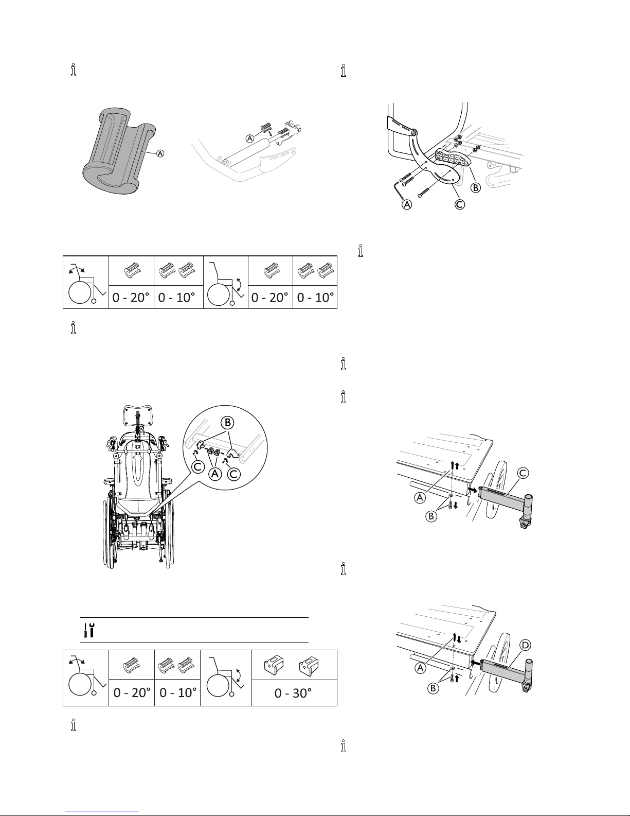
2.12.1Mountingofthetilt/reclinereductionbushing
Thereductionbushingscanbeusedbothfortheseat
tiltandthebackrestreclineonDahlia30ºandfor
thebackrestreclinereductiononDahlia45º.
A
A
1.MountthereductionbushingAonthegaspistonrod
bymanuallypressingitontotherod.
2.RemovethereductionbushingAbymanuallytwisting
itfromthegaspistonrod.
0 - 20° 0 - 10° 0 - 20° 0 - 10°
Whenusingonebushing,thetilt/reclinereductionis
10,withtwobushings,thetilt/reclinereductionis20.
ForinformationaboutseattiltreductionforDahlia
45,seechapter“Mountingtheseattiltreduction
block”.
2.12.2Mountingtheseattiltreductionblock
A
B
C
C
1.PlacethereductionblockAinthesliderattachment
Bontheseatframe.
2.FastenthescrewCandtighten.
3.Repeattheprocedurewiththesecondblock.
TorxdriverT20
0 - 20° 0 - 10°
0 - 30°
Withthesereductionblocksmounted,theseattilt
limitis30.Seechapter“Mountingofthetilt/recline
reductionbushing”forinformationaboutbackrest
reclinereductionforDahlia45.
2.13Repositioningthebackrestjoint
Thewidthextensionspacerscanbeusedwhenthere
isneedforawiderbackrestbar .Thespacerswilladd
anextra25mmspaceoneachside.
A
B
C
1.LoosenthethreescrewsAontheoutsideoftheseat
frame.
Tools:5mmallenkey
2.InserttheplasticspacersBbetweenthebackrest
attachmentCandtheseatframe.
3.RetightenthethreescrewsA(10Nm).
4.Repeattheprocedureontheoppositeside.
2.14Mountingthelegrestattachmentforhigh
position
Withthehighpositionlegrestattachment,the
xationofthelegrestwillbe5cmhigher.
Thehighpositionlegrestattachmentisrecommended
foruserswithaheightof185cmandtaller .
1.
A
B
C
RemovetheupperscrewAandthelowerscrewand
washerB.RemovetheordinarylegrestattachmentC.
Tools:Screwdriver(PH2)forscrewA,allenkey5
mmforscrewB.
2.
D
B
A
MountthehighlegrestattachmentDintheseatframe.
Re-inserttheupperscrewAandthelowerscrewand
washerB.Re-tightenthescrews.
Tools:Screwdriver(PH2)forscrewA,allenkey5
mmforscrewB.
1572308-G
11
Rea®Dahlia®30/45
2.15Mountingtheaccessorytray
1.
X
A
B
B
FixatethenutsandloosenthescrewsBoftheaccessory
trayAandadjustthewidth.
•5mmallenkey
•13mmxedspanner
2.
X
A
C
MounttheaccessorytrayAonthechassis,thehooks
Cshouldbeplacedontheframe.
3.
4x
E
D
SecuretheaccessorytraywiththeattachmentstrapsD.
ThreadthestrapsthroughtheslotEandwrapthem
aroundthehooks.Securetheattachmentstrapsrmly .
4.
B
B
Fixatethenutsandre-tightenthescrewsBtoxate
thewidth.
•5mmallenkey
•13mmxedspanner
Theaccessorytraywillbeinstable
–Alwayssecurethetraywithallfourattachment
straps.
2.16Washsealingkit
Thewashsealingkitcanbeusedtoprotectholesin
thechassisandonthewheelsfromwater .
Contentofthekit
A
4x
C
2x
D
2x
A4stickers
forthe22”–24”
wheelsandthe
Azaleachassis.
C2plugsforthe
16”wheels.
D2plugsforthe
Dahliachassis.
Mountingofthekit
1.
2x
A
B
2x
C
D
22”—24”wheels16”wheels
AttachthestickersAortheplugsCon/intheairholes
BorDofthewheels.
2.
2x
A
E
2x
F
G
AzaleaDahlia
AttachthestickersAortheplugsFintheholesEor
Gofthechassisdependingonmodel.
12
1572308-G
Assembly
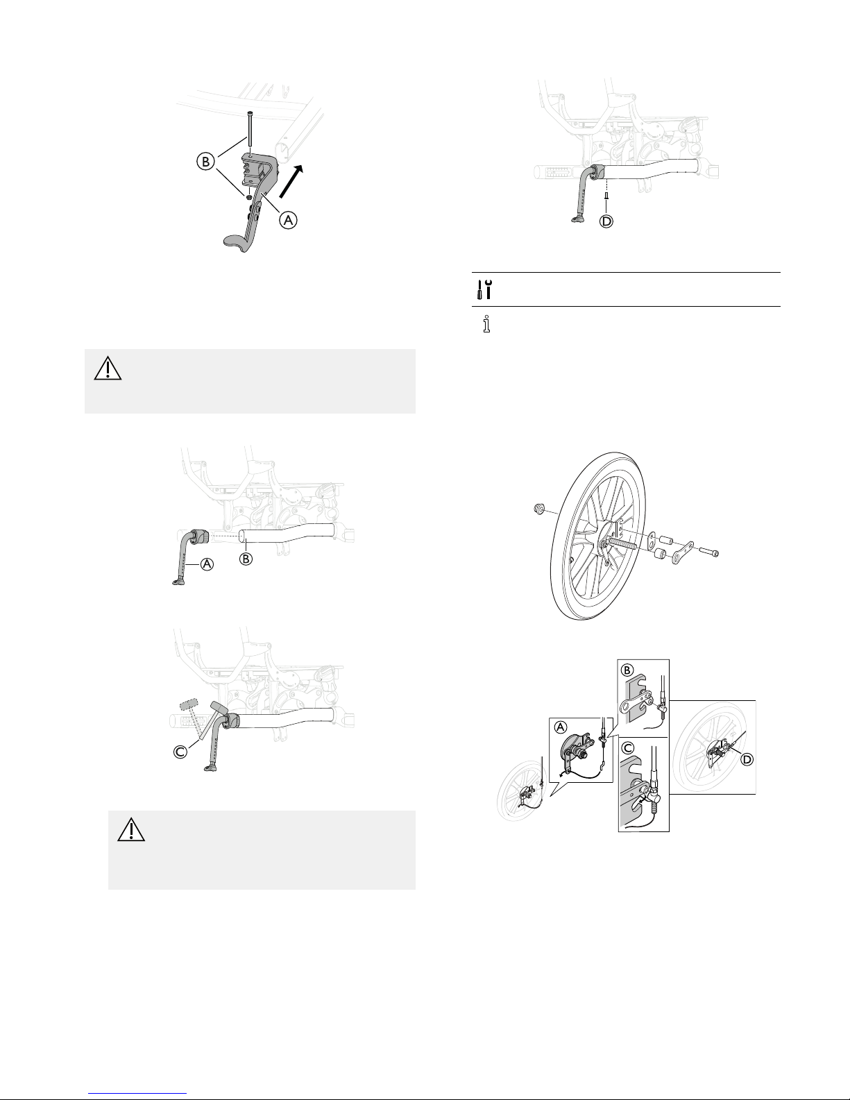
2.17Mountingthekerblever
A
B
1.MountthekerbleverAonthechassistube.
2.MountthescrewandthenutB.
3.Tightenthescrew.
2.18Mountingantitipper
WARNING!
Riskoftipping
–Max.heightfromoortoantitipperis40mm.
Min.heightfromoortoantitipperis15mm.
1.
A
B
MounttheantitipperAinthechassistubeB
2.
C
UsearubbermalletCtoinserttheantitipperinthe
chassistube.
CAUTION!
Damageontheantitippertube
–Donotusetherubbermalletonthe
antitippertube,onlyonthetopofthe
attachment.
3.
D
SecuretheantitipperwiththescrewD.
4.Tightenthescrew.
5.Repeattheprocedureontheoppositeside.
TorxdriverT25orscrewdriver
Seethepart“SizeofAntitipperdevice”inthe
TechnicalDatasectionforinformationaboutthe
sizes.
2.19Mountingthedrumbrake
2.19.1Drumbrakefor16”wheels
1.
Assemblethescrews,washersandnutasshowninthe
pictureabove.
A
B
C
D
2.Mountthewirehookfromthebrakehandleinthewire
holderA.
3.MountthewireintheattachmentwasherB.
4.PlacethewireinthelowernotchonthebrakeC.
1572308-G13
Rea®Dahlia®30/45
5.TightenthescrewDwith9±1Nm.
•5mmallenkey
•10mmxedspanner
WARNING!
Riskofinjury
Poorbrakeeffect
–Checkthebrakeeffectaftermountingor
adjustingthebrake.
F
E
G
H
6.MounttherearwheelaxleEintheattachmentFon
theframe.AttachthenutandspacerGandthescrew
H.
7.TightenthescrewHwith9±1Nm.
8.TightenthenutGwith22Nm.
•Allenkey5mm
•Fixedspanner19mm
9.
I
J
K
Mounttheleverfortheassistantmaneuvereddrum
brakeIonthepushhandleandattachthescrewsJ.
Thedistancebetweenthehandleandthelever
fortheassistantmaneuvereddrumbrakemust
be10—15mmK.
TorxdriverT20
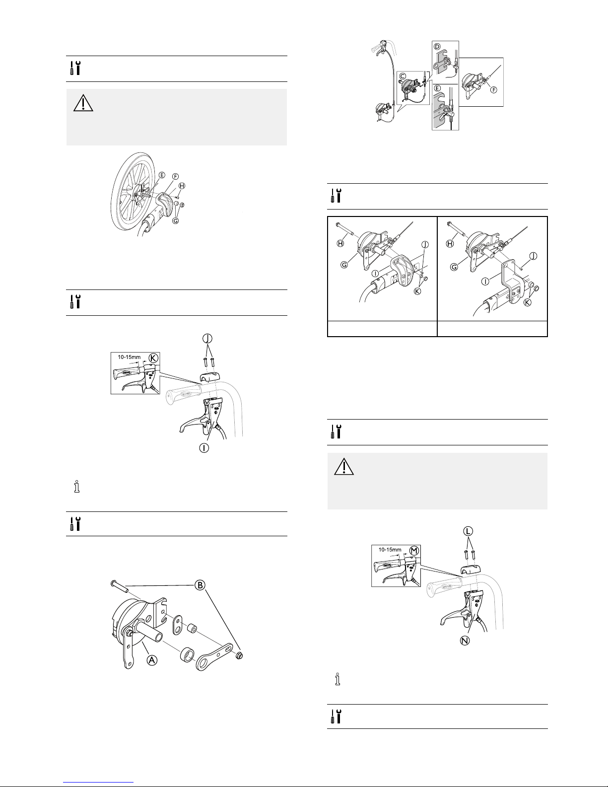
2.19.2Drumbrakefor22–24”
1.
A
B
2.AssemblethepartsonthedrumbrakeAintheorder
shownabove.AttachthescrewandnutBtoxate
theparts.
C
D
E
F
Mountthewirehookfromthebrakehandleinthewire
holderC.MountthewireintheattachmentwasherD
andplacethewireinthelowernotchonthebrakeE.
3.
4.TightenthenutFwith9±1Nm.
•4mmallenkey
•10mmxedspanner
G
H
I
J
K
G
H
I
J
K
LowrearwheelplateHighrearwheelplate
5.AssemblethequickreleaseaxleHthroughthe
rearwheelandthedrumbrakewithwireG.
6.Assemblethewheelwithdrumbrakeontherearwheel
plateI.
7.AttachthescrewJandtightenwith9±1Nm.
8.AttachthenutandsleeveKandtightenthenutwith
40±5Nm.
9.Repeattheprocedureontheoppositeside.
•4mmallenkey
•24mmxedspanner
WARNING!
Riskofinjury
Poorbrakeeffect
–Checkthebrakeeffectaftermountingor
adjustingthebrake.
10.
N
L
M
Mountthehandlefortheassistantmaneuvereddrum
brakeLonthepushhandleandattachthescrewsM.
Thedistancebetweenthehandleandthehandle
fortheassistantmaneuvereddrumbrakemust
be10—15mmN.
T20torxdriver
14
1572308-G
Assembly
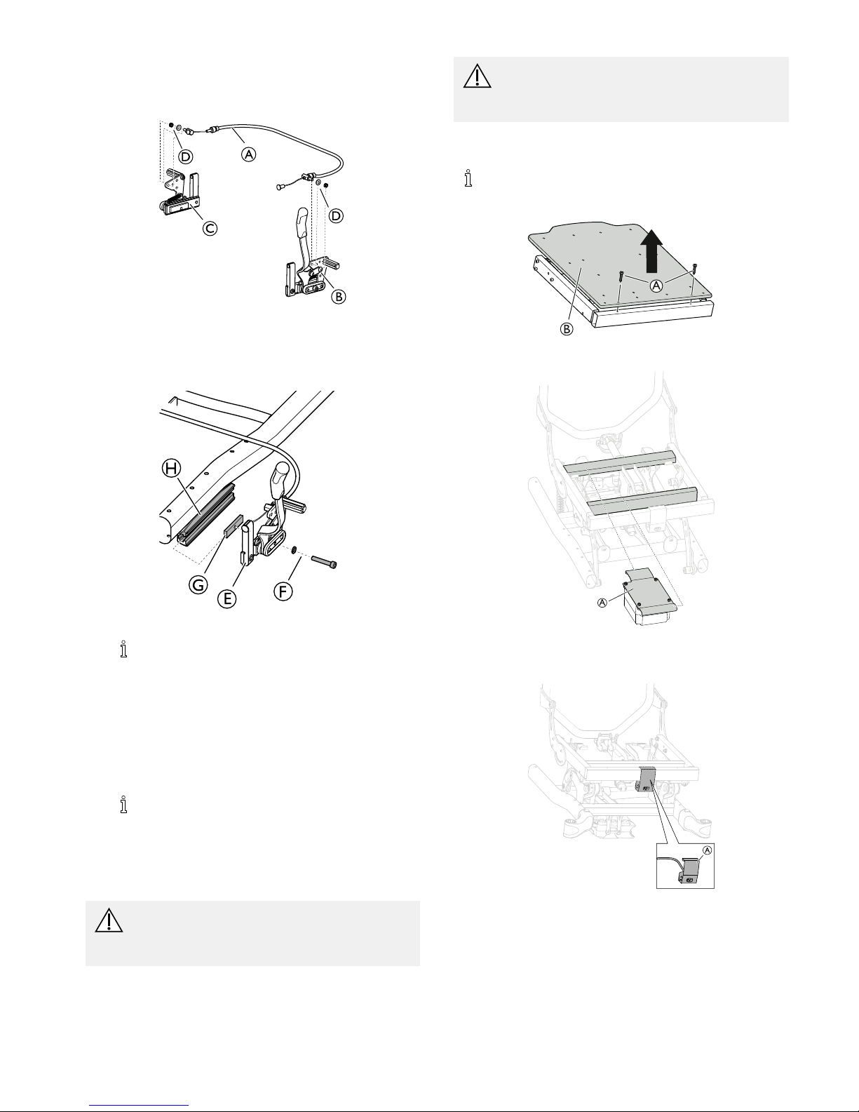
2.20MountingthewirefortheOnearmbrake
A
B
C
D
D
1.AttachthewireAtobothsidesofthebrakeBandC.
2.FixatethewirewiththenutandwasherD.
2.21MountingOnearmbrake
F
G
H
1.AttachthebrakeEtotheattachmentnutG.
Insomecongurations,theattachmentnutG
needstobeplacedintheattachmentHprior
toattachingthebrake.
2.FixatetheattachmentnutGwiththescrewandwasher
F.
3.AttachthebrakeEandtheattachmentnutGtothe
attachmentonthechassisH.
4.Adjustthedistancebetweenthebraketapandtherear
wheel.
5.Adjustthebrakeeffect.
Seesection“ Adjustingthebrake”formore
information.
6.TightenthescrewF.
7.Repeattheprocedureontheoppositeside.
2.22Mountingtheelectricaltilt
WARNING!
Riskofinjury
–Makesurethatallpartsaredisconnectedfrom
thepowersource.
CAUTION!
Riskofshortcircuit
–Beawareofelectrostaticdischarge(ESD)when
workingonelectricalparts.
2.22.1Mountingthebattery
Whenchangingthebattery,thehandcontrolcable
needstobeconnectedforatleast10secondstobe
abletoindicatethelevelsofthenewbattery.
A
B
1.LoosenandremovethescrewsAandtheseatplateB.
A
1.MounttheattachmentwiththebatteryAontheframe.
Mountingtheholderforthemainscableextension
A
1572308-G15
Rea®Dahlia®30/45
1.PlacetheholderAonthemarkedareaoftheframe.
2.Attachthemainscableextensiontothecontrolbox.
Seesection“Electricalschedule”formore
informationabouthowtoconnectthecables.
WARNING!
Damagetothebatterycable
–Makesuretofastenthecablesinaway
thatkeepsthecablesfrombeingsqueezed
orstretched.
–Checkthatthecablesrunfreelywhenusing
thetiltand/orreclinefunction,
A
B
3.Re-mounttheseatplateB.
4.TightenthescrewsA.
2.22.2Chargingthebattery
Damagetothebattery
–Thebatterymustbecharged24hoursbefore
usingthesystemthersttime.
–Unplugthemainscableafterchargingbefore
usingthewheelchair .
Thebatterychargerhasdifferentchargingcablesin
ordertoadapttodifferentlocalelectricalstandards.
Whenthebatterylevelislow(20%),thesystem
beepswhenitisinuse.
Connectchargercable
CAUTION!
Damagetothecables.
–Donotsitinthewheelchairwhilechargingthe
battery.
A
A
A
B
1.Connectthechargercablesuppliedwiththechairintoa
wallsocket.
2.InsertthechargercableAintotheconnectorBwhich
islocatedonthefrontofthewheelchair.
3.Unplugthecablewhenthebatteryisfullycharged.
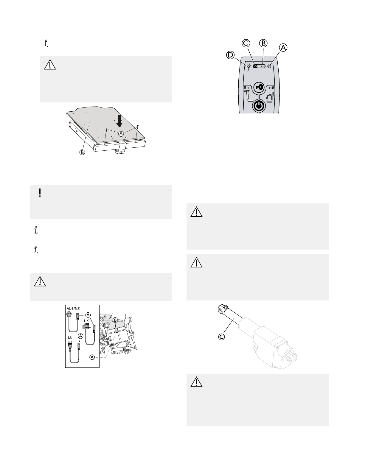
Handcontrol—Batteryindications
A
BC
D
A
Greenlight—ON—Handcontrolisactivated
B
•Greenlight—ON—Batterylevelisabove20%
•Greenlightblinking—ON—Batteryischarging
(xedlightwhenthebatteryisfullyloaded)
C
•Y ellowlight—ON—Batterylevelislow,below
20%
D
Greenlight—ON—Batterycableisconnected
(lightsupabout5secondsafterconnectingthe
cable)
2.22.3Mountingtheactuators
WARNING!
Riskofinjury
Thewheelchairmaycollapse
–Checkthatthelockingwashersaresecurely
locked.
–Ifthesafetypinisused,makesurethatthe
lockshackle/loopissecurelylocked.
WARNING!
Safetyrisk
Thewheelchairmaycollapse
–Remembertoalwaysreinsertandfastenthe
safetypinwhenithasbeenremoved.
–Checkthatthelockshackle/loopissecurely
locked.
C
WARNING!
Electricalversion
Thebackrestmaycomelooseifthepistonrodis
accidentallydetachedfromitshousing.
–Beforeattachingthepistontothebackrest,
turnthepistonrodCmaximumclockwise.
–Whenaligningtheholes,onlyturnthepiston
rodCmaximumahalfturncounterclockwise.
161572308-G
 Loading...