

Invacare Rea Comfort, Rea Assist Assembly Instructions Manual
Rea Comfort
Rea Assist
Assembly instructions
Accessories
English

2 REA ASSIST & COMFORT

3
REA COMFORT
Contents
REA COMFORT
Drive wheels 5
Te tra quick release 6
Hand rims 7
Spoke-guards 7
Castors 7
Tr ansportation wheels 8
Brake 9
Carer-operated brake 10–11
Backrest extension 12
Headrest/Neck-rest 12
Central support 13
Lower back support 13
Tr unk support 14
Safety belt 14
Hemiplegic armrest 15
Lock-kit armrest 15
Sliding seat 16–17
Backrest bar 18
Backrest bar with push handles 18
Widening kit 19
Knee-guard 20
Pommel 20
Footrest bracket 21
Amputee legrests 21–22
Heel strap 23
Calf rest 24
Refl ector kit 25
Tr ay 26
Bag 26
Crutch holder 27
Incontinence cover 27
Manual angling of the backrest 28
Electrically powered tilting and angling of the backrest 29-32

4 REA ASSIST
Contents
REA ASSIST
Transportation wheels 33
Castors 34
Chassis extension 35
Manual tilting and angling of the backrest 36–39
Electrically powered tilting and angling of the backrest 40
Fitting the battery 41
Backrest bar 42
Adjustable backrest 42–43
Backrest extension/Neck support 44
Headrest/Central support 44
Lower back support 45
Cushion stop 46
Leg divider 46
Safety-belt 46
Hemiplegic armrest 46
Lockable armrest 47
Central legrest 47
Leg rest 48
Heel strap 48
Tr ay 49
Tr unk support 50
Bag 50
Refl ector kit 51
Crutch holder 51
Incontinence cover 52
Further accessories (not shown in diagrams) 53
5
REA COMFORT
A
B
B
1.
2.
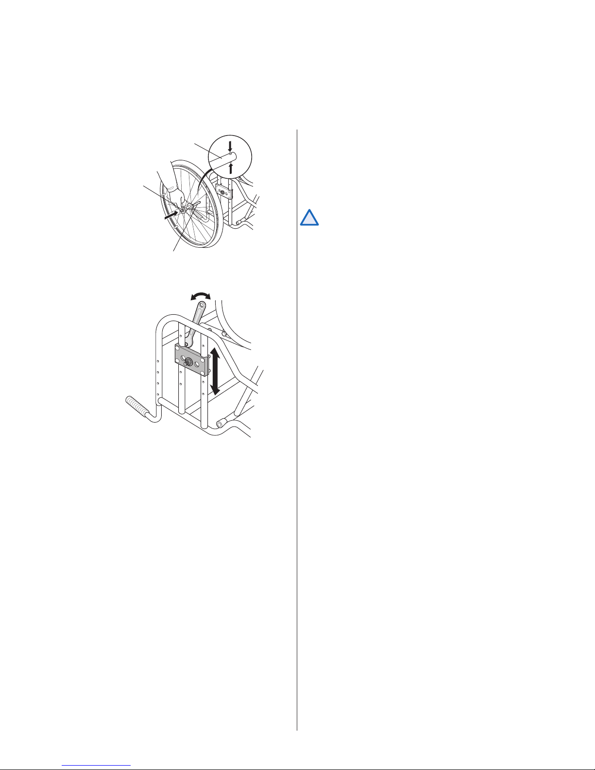
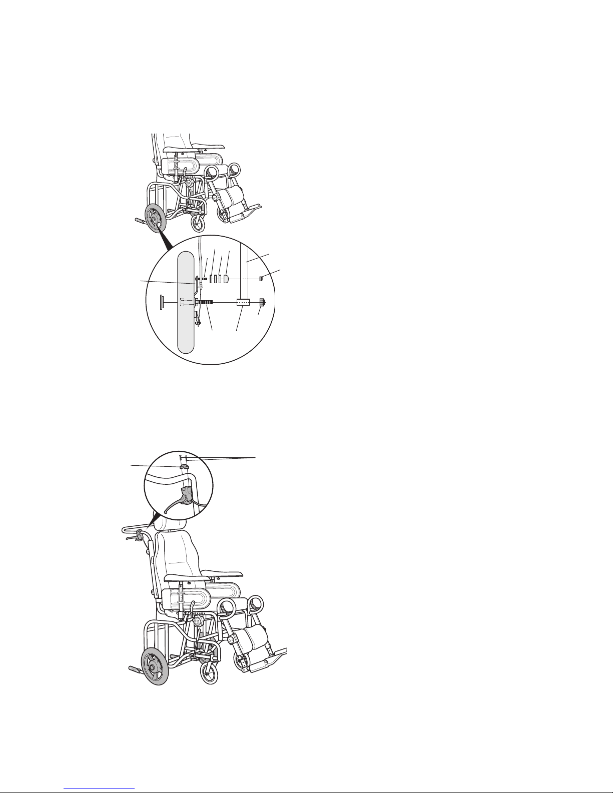
Drive wheels
1. Attach the drive wheel by depressing spring-
loaded button (A), at the centre of the hub. Keep
it depressed, while simultaneously feeding axle
(B) into the hub.
It is very important that you check that the
locking pin has actually locked the wheel
into position when the centre button has
been released. Take hold of the wheels and
try to detach them. This should NOT be
possible.
2. The drive wheel plate can be moved by using a
fixed spanner to slacken and remove the nuts.
!
6 REA COMFORT
A
B
C
D
A
E
1.
2.
3.
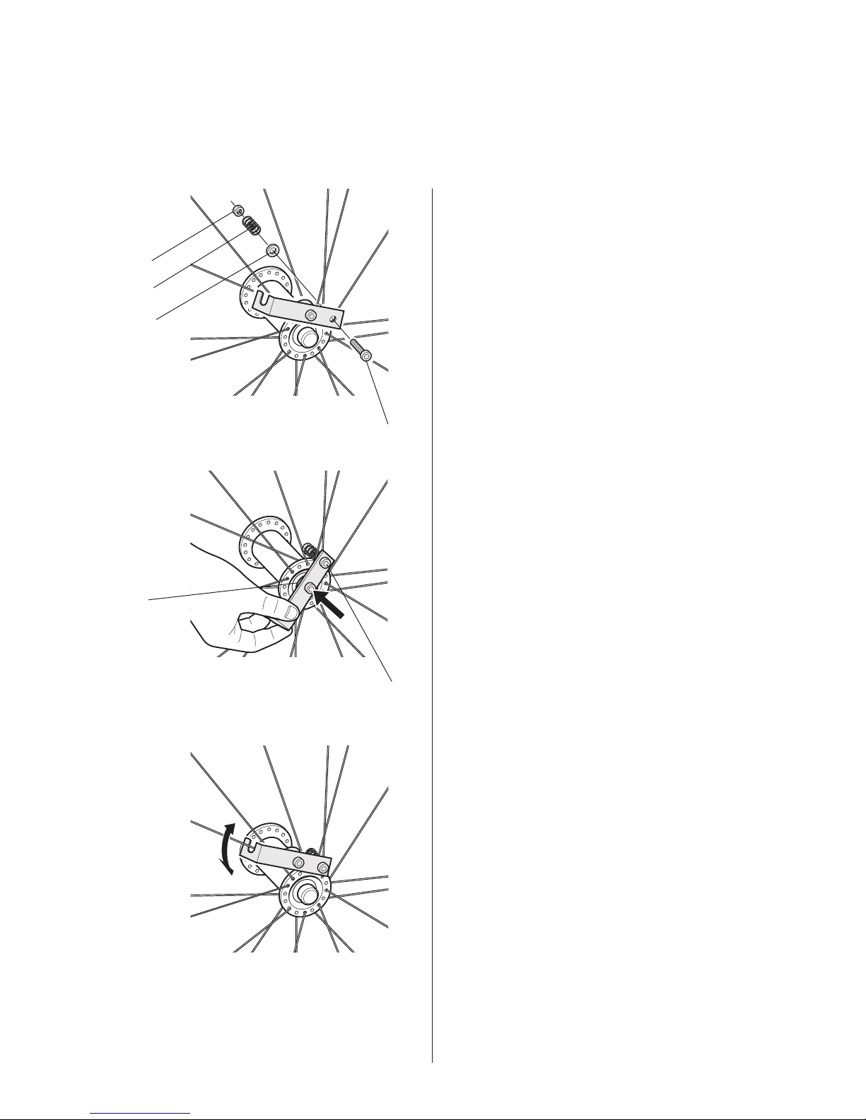
Tetra quick release
1. Fit the push handle securely in the space
between the spokes, closest to the hub. Use
screw (A), washer (B), spring (C) and nut
(D).
2. Rotate the push handle so that the spacer
(E) touches the rear wheel’s release button
when pushed inwards. Adjust the spring effect
using screw (A).
3. When the push handle is not in use, you must
hook it securely round a suitable spoke as
shown in the picture.
Tools: 4 mm Allen Key
8 mm Spanner
7
REA COMFORT
B
A
A
C
A
A
B
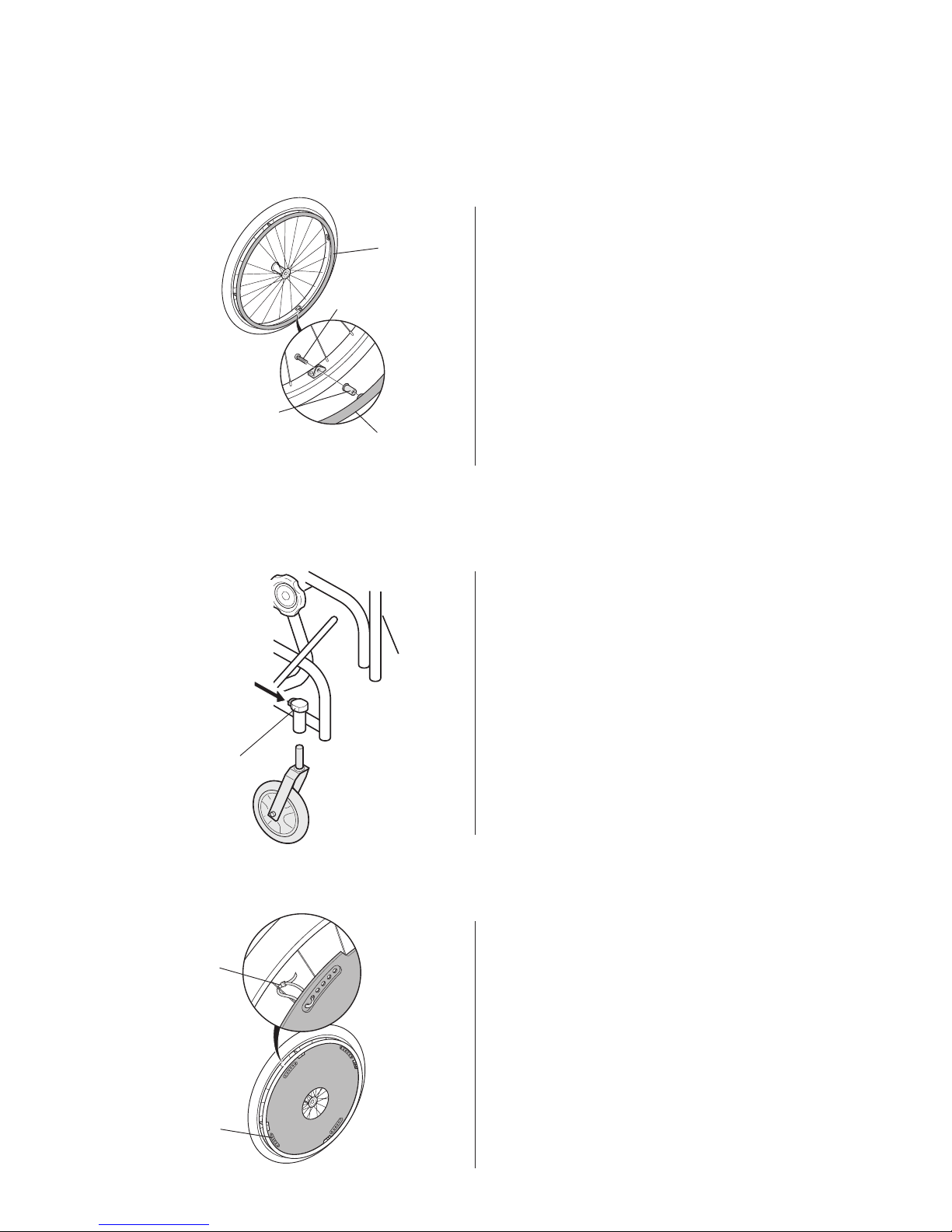
Position the spoke-guard so that its recesses (A)
are in alignment with the hand-rim fi xing points. Use
tying tags (B) to secure it in position. When tied in
position, cut off any excess tag.
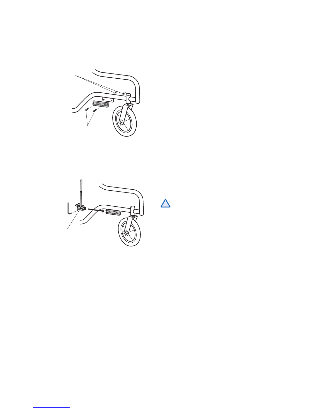
Castors (+ castor forks) are removed by first
depressing button (A) and then pulling the castor (+
castor fork) directly downwards.
Spoke-guards
Use screws (B) and spacers (C) to attach the hand
rims (A) to the wheels.
Hand rims
Castors
Tools: Screwdriver
8 REA COMFORT
B
A
2.
1.
D
G
G
H
E
I
AB
C
F
Transportation wheels
1. Carer-operated brake
To fi t the carer-operated brake, fi rst remove the
drive wheel plate (see page 3). Then slide the
12” wheel axle (A) into tube (B). Use nut (C) to
secure it in position.
To fix the brake unit in position screw (D) should
be located into tube (E). This is done by inserting
screw (D) through the hole in plate (F). The
plastic washer (G) and spacer (H) should be
fitted between the plate and the tube. Finally,
tighten nut (I) onto screw (D), on the other side
of the tube.
2.
The brake lever is attached to the push handle
by holding fi tting (A) above the handle and then
locating the brake lever underneath. Secure in
position with screws (B).
There are three different brake positions.
Tools: 10 mm fi xed spanner
19 mm fi xed spanner
19 mm hylsnyckel
Tools: Screwdriver
9
REA COMFORT
C
B
A
1.
2.
!
Brake
1. Use screws (A) and nuts (B) to attach the brake
bracket to its mounting plate.
2. Slide the brake into the bracket, insert an Allen
key into the hole and tighten screw (C).
Incorrect adjustments or use of the brake can
reduce the effectivieness of the brake.
Tools: 4 mm Allen Key
10 mm fi xed spanner
Tools: 5 mm Allen Key
10 REA COMFORT
1.
A
B
2.
B
3.
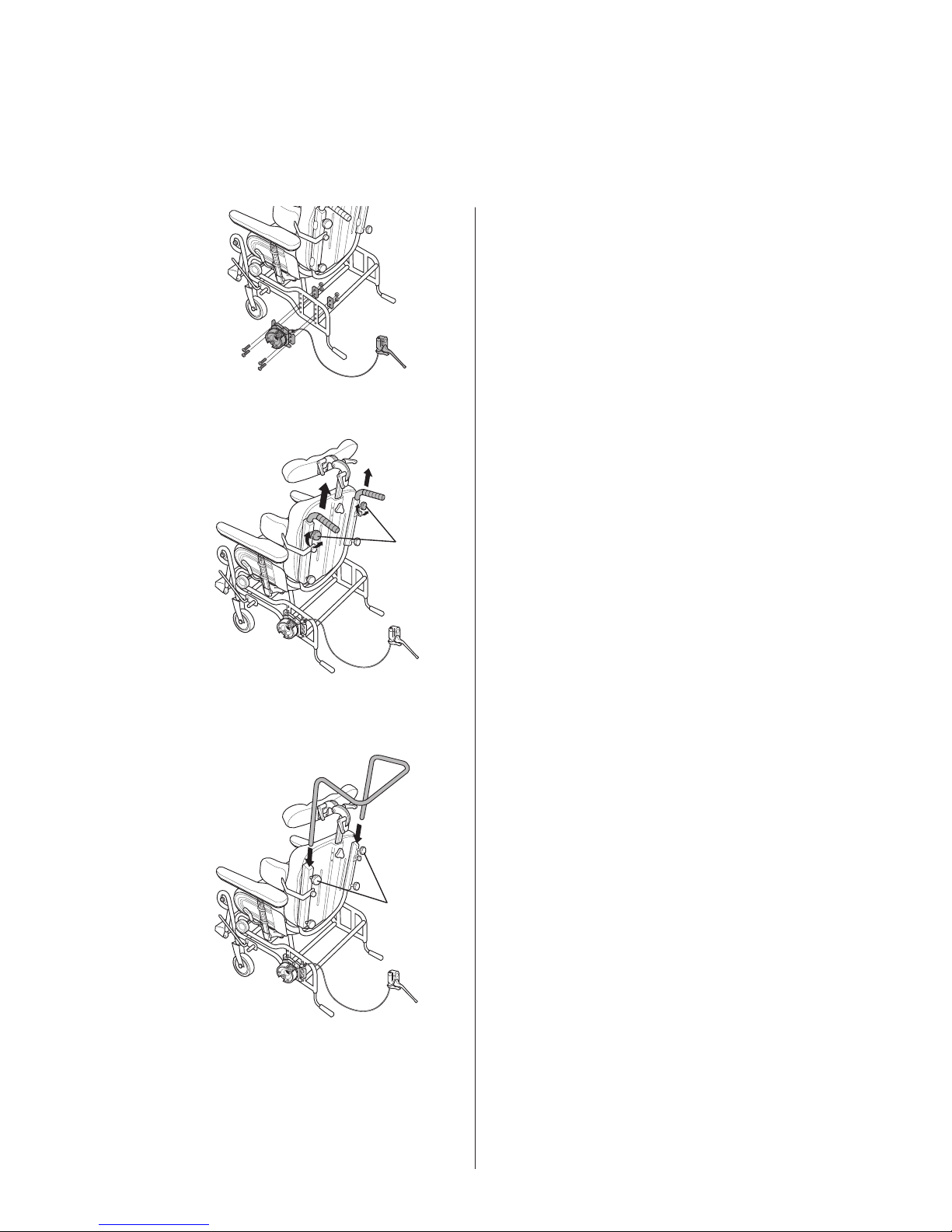
Carer-operated brake
1. Remove the existing drive wheel plate by removing
screws (A). Fit The new plate with the appropriate
screws.
2. Remove the existing push handles by slackening
the knobs (B) and then pulling the push handles
directly upwards.
3. Insert the push bar into the backrest tubes and
secure them in position by tightening knobs (B)
Tools: 10 mm fi xed spanner
11
REA COMFORT
4.
5.
6.
E
D
C
E
D
C
B
A
!
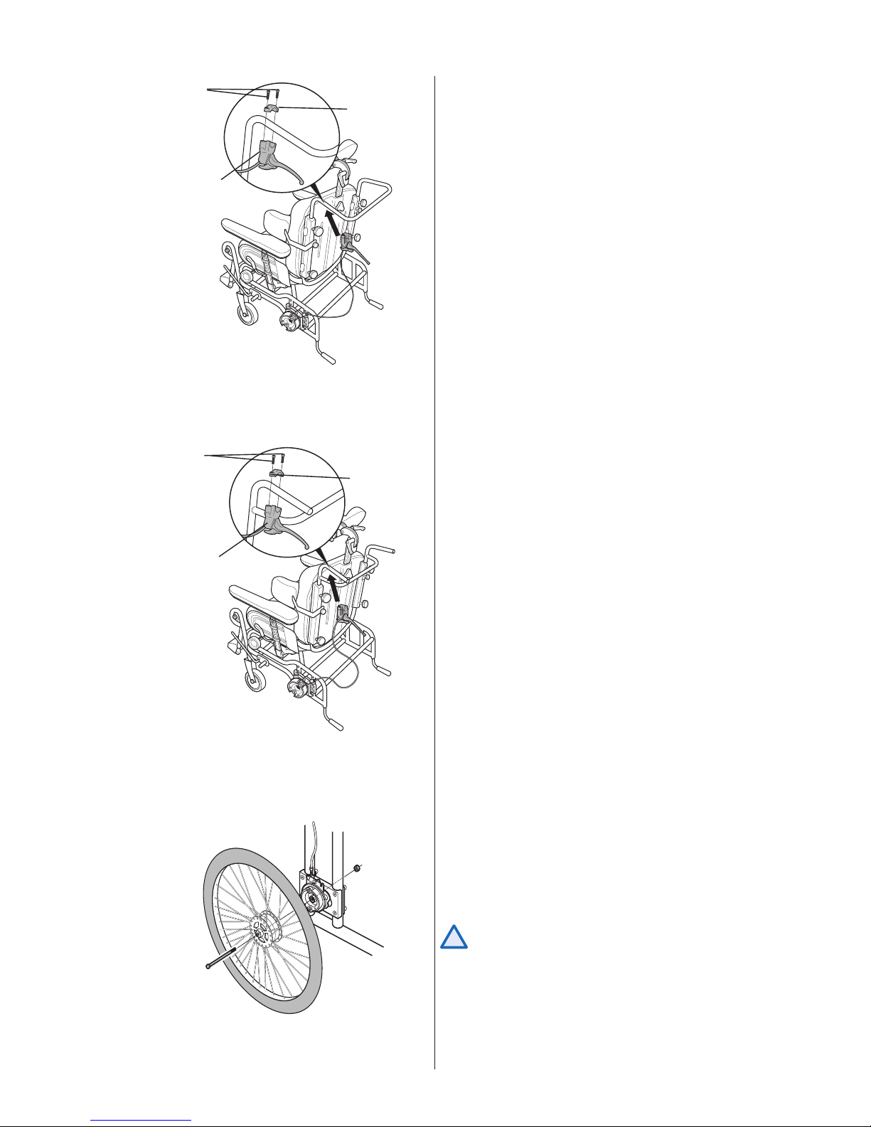
4. The brake handle is secured in position by
locating brake lever (C) under the push bar and
plate (D) above it. Then secure in position with
screws (E).
With push bar
Tools: Screwdriver
With push handles
Tools: Screwdriver
5. The brake handle is secured in position by
locating brake lever (C) under the push bar and
plate (D) above it. Then secure in position with
screws (E).
6. The new rear wheel can be mounted either
by using a Quick-Release axle or a fi xed axle.
Mount the fi xed axle by inserting the axle (B) into
the hub of the wheel and tightening it against the
rear wheel attachment with the nut (A)
Incorrect adjustments or use of the brake can
reduce the effectiveness of the brake.
Tools: 19 mm fixed spanner
19 mm hylsnyckel
12 REA COMFORT
A
B
E
C
D
A
!
F
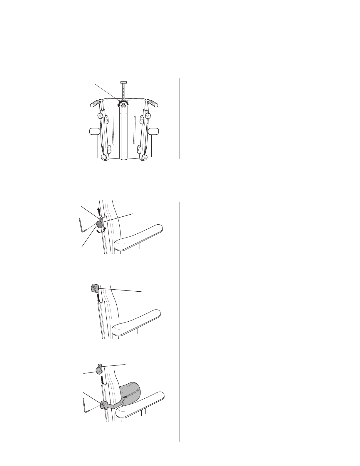
Fix the headrest/neck-rest into the top of the central
support and secure in position with knob (A).
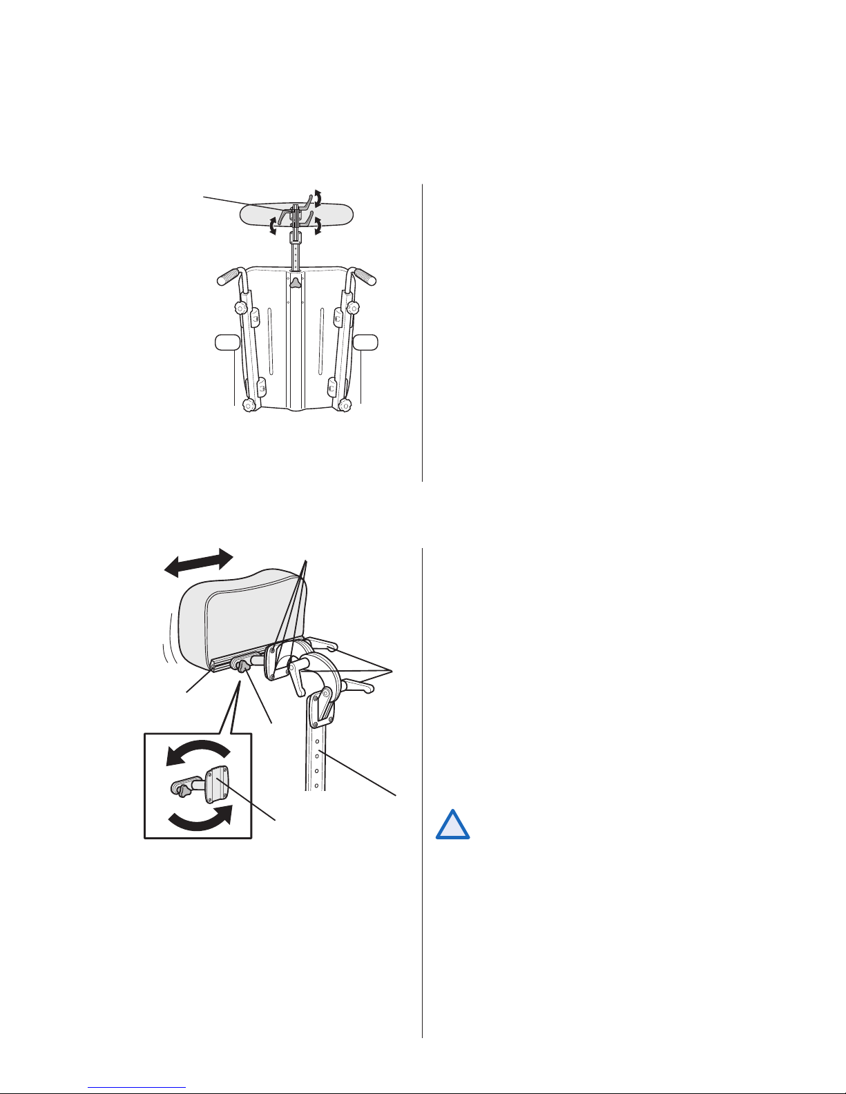
Headrest/Neckrest
To adjust the neckrest/headrest sideways loosen the
knob/screw (A). Adjust to a new position and tighten
the knob/screw (A). Adjust the angle and height by
loosen the handles (B). Change to a new position and
tighten the handles (B).
To get maximum sideway movement you can turn
around the attachment (C). The knob/screw (A)
shout sit on the left side of the attachment to get
maximum sideway movement to the left and on the
right side of the attachment to get maximum sideway
movement to the right.
Ta ke away the attachment (C) by loosen the screws
(E) and the screw (D), take out the attachment and
turn around to required position. Re-tighten the
screws (E) and the screw (D).
If the neckrest/headrest has been taken
away, The central support (F) mustn't be
left on the chair.
ADJUSTABLE HEADREST/NECKREST
13
REA COMFORT
A
C
E
A
C
B
A
D
3.
2.
1.
Slide the central support into the required position in
its bracket and secure in position with knob (A).
Central support
1. Slacken knob (A) and screw (B). Lift locking device
(C) directly upwards.
Trunk support
2. Fit the trunk support bracket (D) into the slot
and slide it to the required height.
3. Secure the trunk support bracket in position with
Allen screws (E).
Refi t the locking device (C) and ensure that knob
(A) is tightened.
Tools: 5 mm Allen Key
Tools: 5 mm Allen Key
14 REA COMFORT
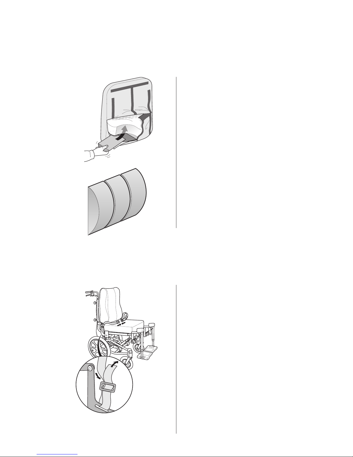
When fi tting the lower back support, fi rst remove the
backrest cover. Then, position the lower back support
in the required position and refi t the backrest cover.
Remember that the cloth fl ap inside the backrest
cover should be pulled to the rear side, through the
slot in the foam cushion.
Lower back support
Safety belt
The safety-belt should be attached to the brackets
at each side of the wheelchair. Feed the belt through
the bracket and buckle and adjust it to the required
length.
15
REA COMFORT
A
A
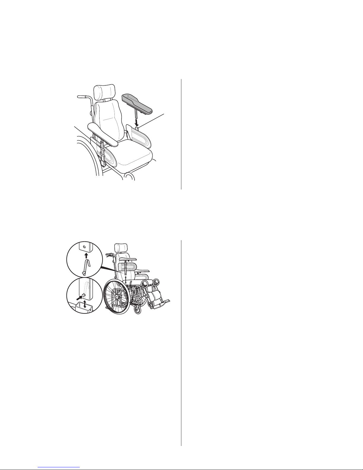
Slide the hemiplegic armrest into the bracket located
on the wheelchair’s side-guard.
Set it at the required height and tighten knob (A).
Hemiplegic armrest
Press the autolock spring together slightly and
feed it up into the armrest tube. Ensure that the
button is placed correctly into the hole on the
armrest tube.
The button must be pushed in to enable the armrest to
be fi tted into/removed from the armrest attachment
on the chassis.
Lock kit for armrests
16 REA COMFORT
A
B
C
E
D
F
F
E
D
C
1.
2.
3.
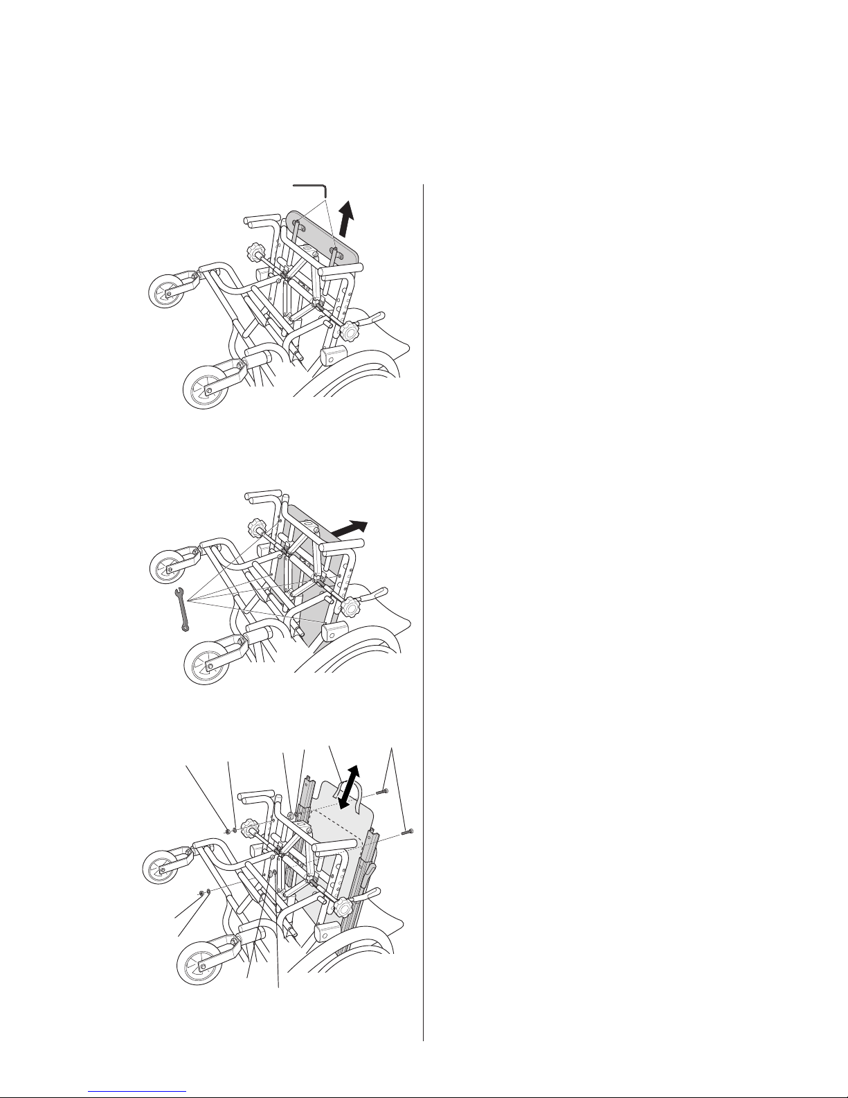
Sliding seat
1. To fi t the sliding seat: Remove the existing seat
pad, armrests and legrests. Lay the wheelchair
down on the floor, loosen both screws and
remove the seat extension.
2. Remove the existing fl at seat by loosening the
four nuts.
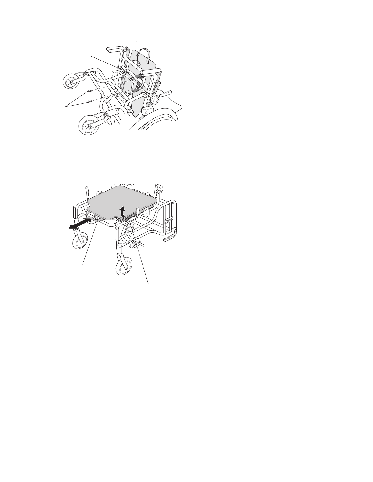
3. Pull the handle (A) and move the sliding seat
forwards as far as possible. Then attach the rear
section of the seat to the chassis on the right and
left sides using the screw (B). Place the plastic
washer (C) and spacer (D) between the sliding
seat’s rails and the chassis. Secure into place using
washer (E) and nut (F) on the underside. Then pull
the seat as far back as possible and secure the
frontal section of the seat in the same way.
17
REA COMFORT
A
B
A
C
B
4.
5.
4. Then secure the seat stop (A) in the predrilled
holes in the seat by tightening the screws (B).
It is important that the seat stop is placed as
shown in the picture so that the cross tube
(transverse tube) (C) is used as a stop.
5. To adjust the sliding seat, move the lever (A)
upwards at the same time as you pull the handle
(B) and move the seat either backwards or
forwards. It is easier to adjust the seat when the
user is sitting in the wheelchair.
 Loading...