

Invacare Rea Bellis User Manual
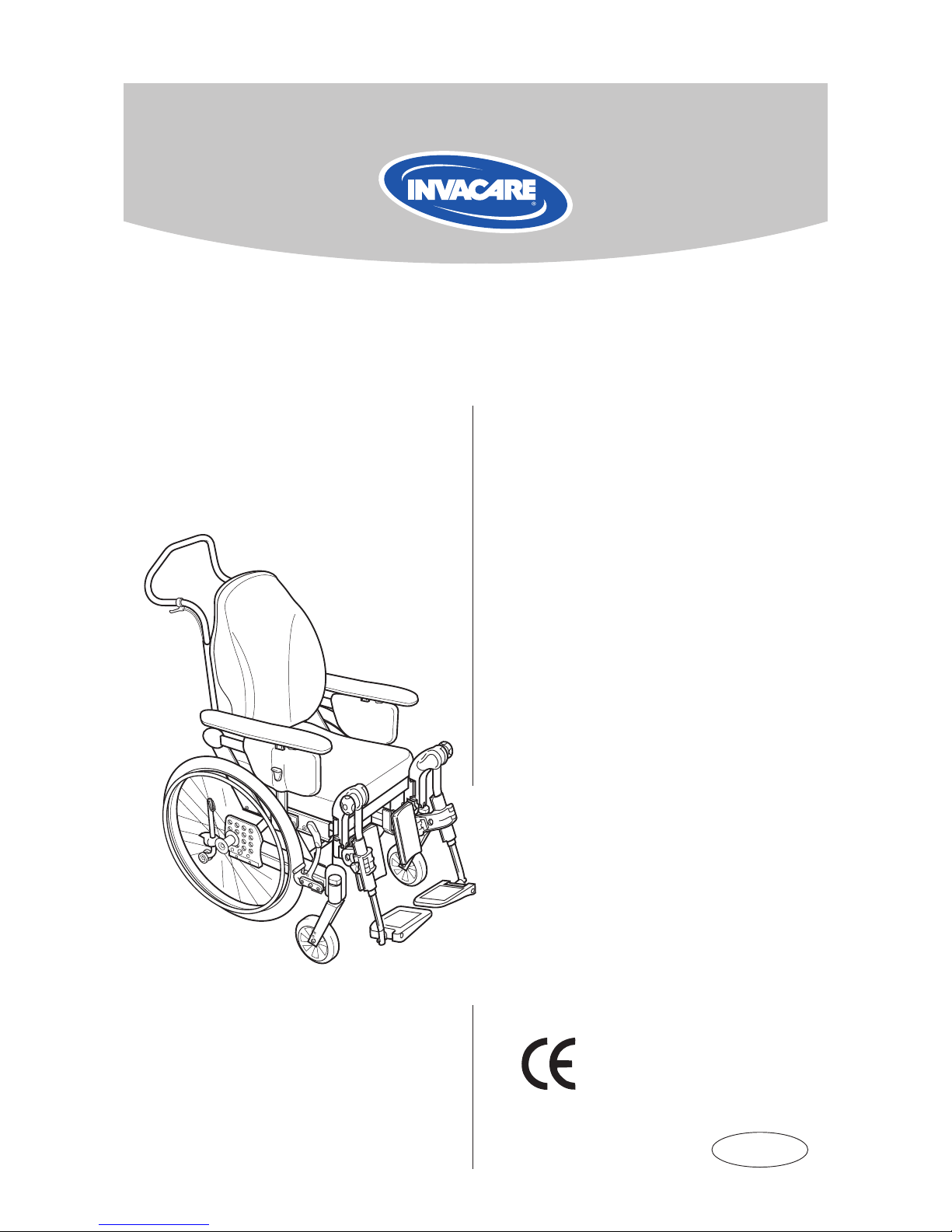
Rea® Bellis
Manual
English

2
REA® BELLIS
3
REA® BELLIS
!
Read the back cover of this user’s manual, which features
a number of points affecting your personal safety. Read it
carefully!
Invacare is only responsible for product changes carried
out by personnel who we authorise. We reserve the right
to make any changes to equipment and specications without prior notice.
Rea® Bellis is a wheelchair with many adjustment options
and accessories. To ensure that you benet as much as
possible from Rea® Bellis, and in order to do its options
justice, the chair must be tested and adjusted by competent personnel. We hope that you have also received
instructions for using your Rea Bellis in everyday life.
This manual includes a description of the parts of the
chair, simple adjustment options, how to use the Rea®
Bellis safely and how to transport it. The manual must be
read thoroughly before the chair is used.
Also included in this manual is a description of how all
accessories are tted and slightly more advanced settings.
As the Rea® Bellis has many different components and
accessories, the appearance of the accessories you have
for your chair may differ from those shown.
Check that all components match the delivery note. Any
transport damage must be reported immediately to the
transport company. Remember to keep the packaging until
the transport company has checked the goods and a settlement has been reached.
Rea® Bellis
Delivery check
NB!

3
REA® BELLIS
Contents
Parts of the wheelchair 4
Standard equipment 5
Upholstery and frame colours 5
Accessories 5
Technical data – Rea Bellis 6
Assembly 7
Adjustments 9–20
Seat 9
Legrests/footrests 10
Footplates/calf pads 10
Central footplate 11
Backrest 13
Armrests 13
Seat unit 14
Manual chair with gas piston 14
Electrically operated chair 15
Rear wheels 16
Wheelchair heights 17
Frame extension 18
Brake 18
Carer-operated brake 19
Push handles/push bar 19
Anti-tip device 20
Transport 21–24
Transport of wheelchairs in vehicles 23
Observations 24
Restraint methods 25
Safety instructions/propelling techniques 26
Product description 28
Application 28
Guarantee 29
4
REA
REA® BELLIS
9
3
1
2
10
8
11
7
5
6
4
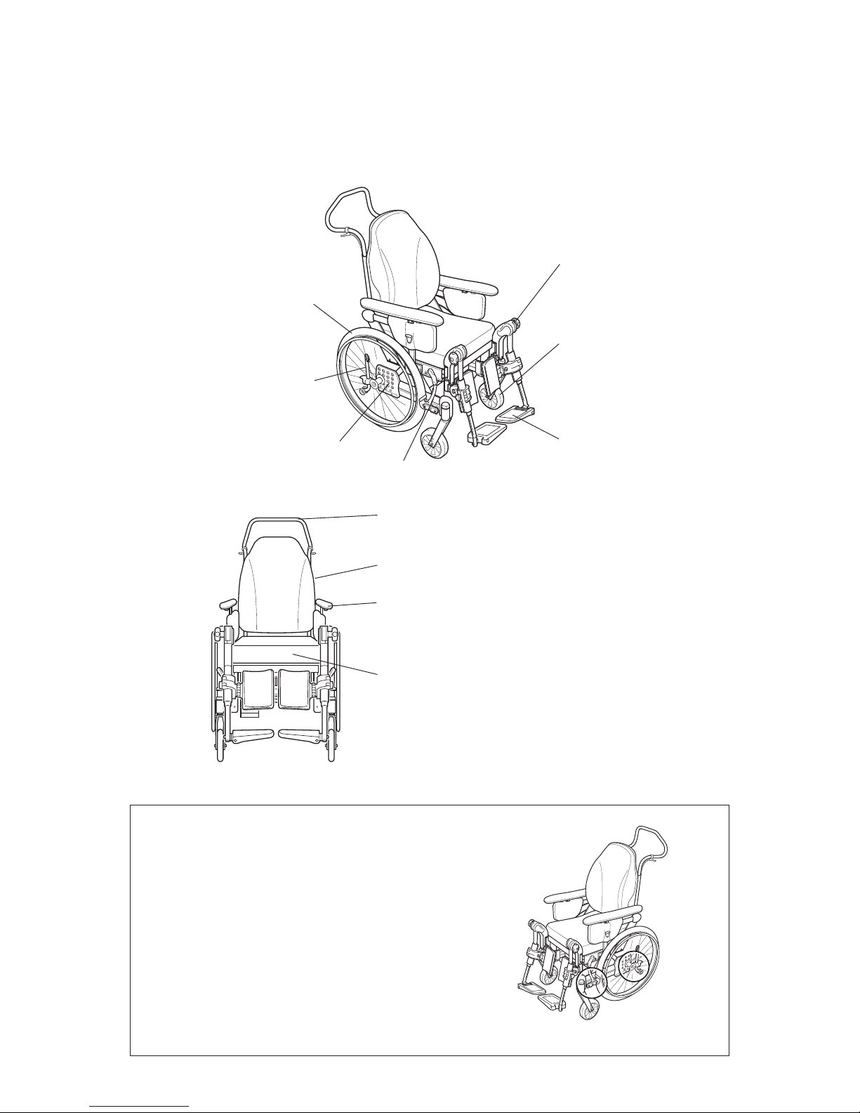
Parts of the wheelchair
1. Backrest
2. Push bar
3. Armrest
4. Rear wheel
5. Rear wheel plate
6. Anti-tip device
7. Brake
8. Castor
9. Seat
10. Legrest/Footrest
11. Foot plate
Lifting the wheelchair
Only lift by the frame of the chair (as shown in the
diagram). This applies at all times, irrespective of whether
when the user is or is not seated in the chair. Never lift
the chair by the removable armrests or by the footrests.
Ensure that the backrest and push bar are properly
secured.

5
REA® BELLIS
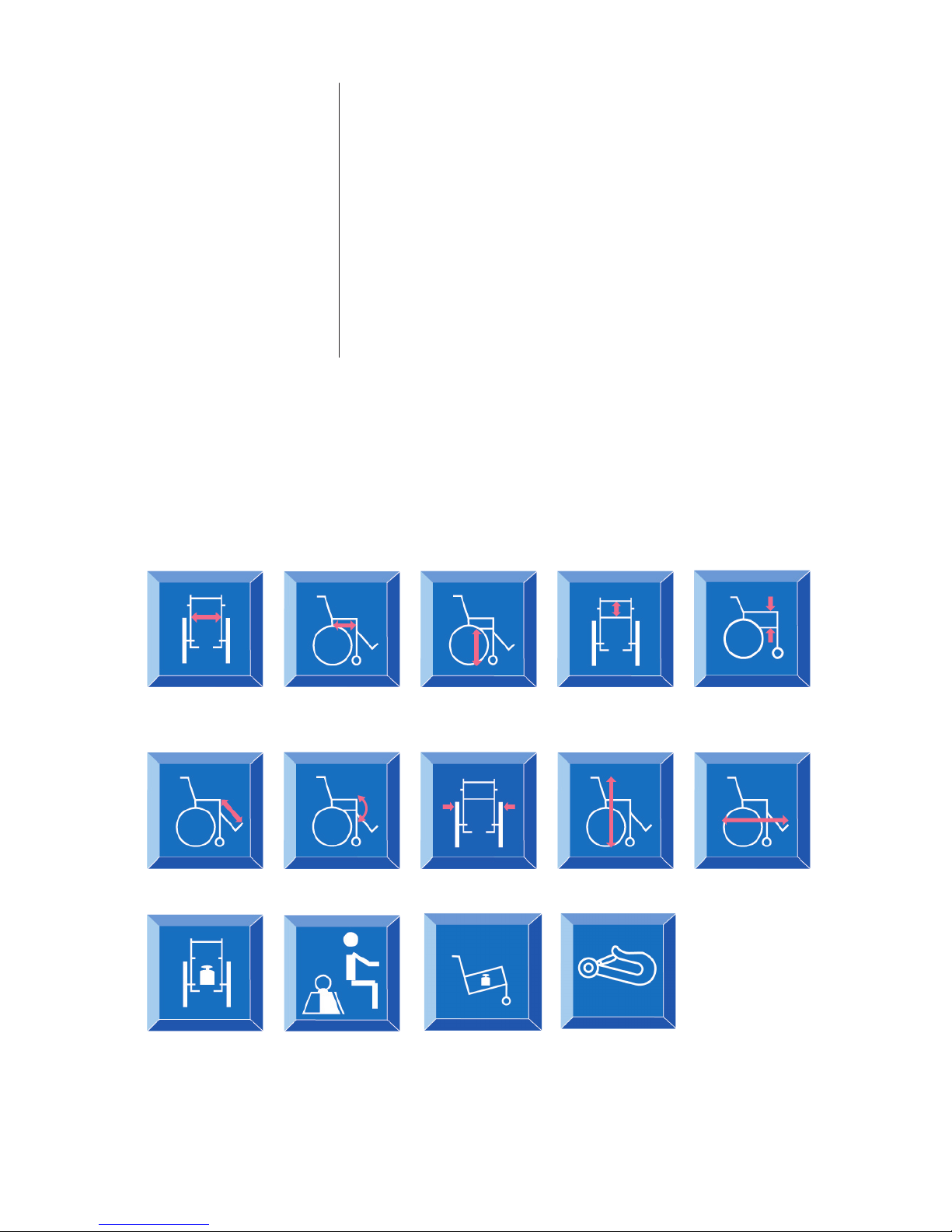
Accessories
Standard equipment
Seat width: 39*– 41– 43*cm
44*– 46– 48*cm
49*– 51– 53*cm
Seat depth: 40–52 cm
* with ip-up armrests (Nice)
Upholstery:
Green plush, "Strix"
Bordeaux plush
Grey dartex
Frame colours:
Dark blue RAL5013
Bordeaux CRED 2
Upholstery and frame colours
The Rea® Bellis has a wide range of accessories and options. Some of the accessories may not be available in certain countries.
Backrest Standard
Adjustable backrest
Seat Standard
Seat cushions Mistral
Seat and Carer-operated
backrest angle Electrical operated by carer/user
adjustment
Legrests Legrests (angle-adjustable)
Amputee legrests
Footrests
Fixed footplate
Angle-adjustable and depth-adjustable
Foot plate extender
Heel strap
Castors 120–200 mm, pneumatic or solid, wide or narrow
Rear wheels 16", 20", 22", 24", pneumatic or puncture-proof
Vortex operating unit
Brakes Carer-operated
User brake
One-arm brake
Foot brake
6
REA® BELLIS
REA
Others Several types of hand rim
Several types of spoke guard
Reectors Kit
Table Tray
Pump
Cane holder
Bag
Headrest
Neckrest
Push bar
Push handles brace
Pelvic Belt
Abduction cushion
Incontinence cover
41, 46, 51 cm
40 –52 cm 36 – 48,5 cm 52+7 cm 23–33 cm
29–51 cm -1°–+15° SW + 20,5 cm 110 cm 92–104 cm
32 kg
max 125 kg
*
transport weight 20 kg
*
Maximum user weight is 100 kg if the chair is tted with 100–120 mm castors.
**Our wheelchairs comply over and above ISO normal standards plus ISO 10542, which have additional features pro-
viding increased levels of occupant security and safety whilst travelling in a motor vehicle. Wheelchair users should
however transfer to the vehicle seat and use the vehicle installed restraint system whenever it is feasible.
Technical data – Rea® Bellis
Tie down point**
REA® BELLIS
7
1.
2.
3a.
A
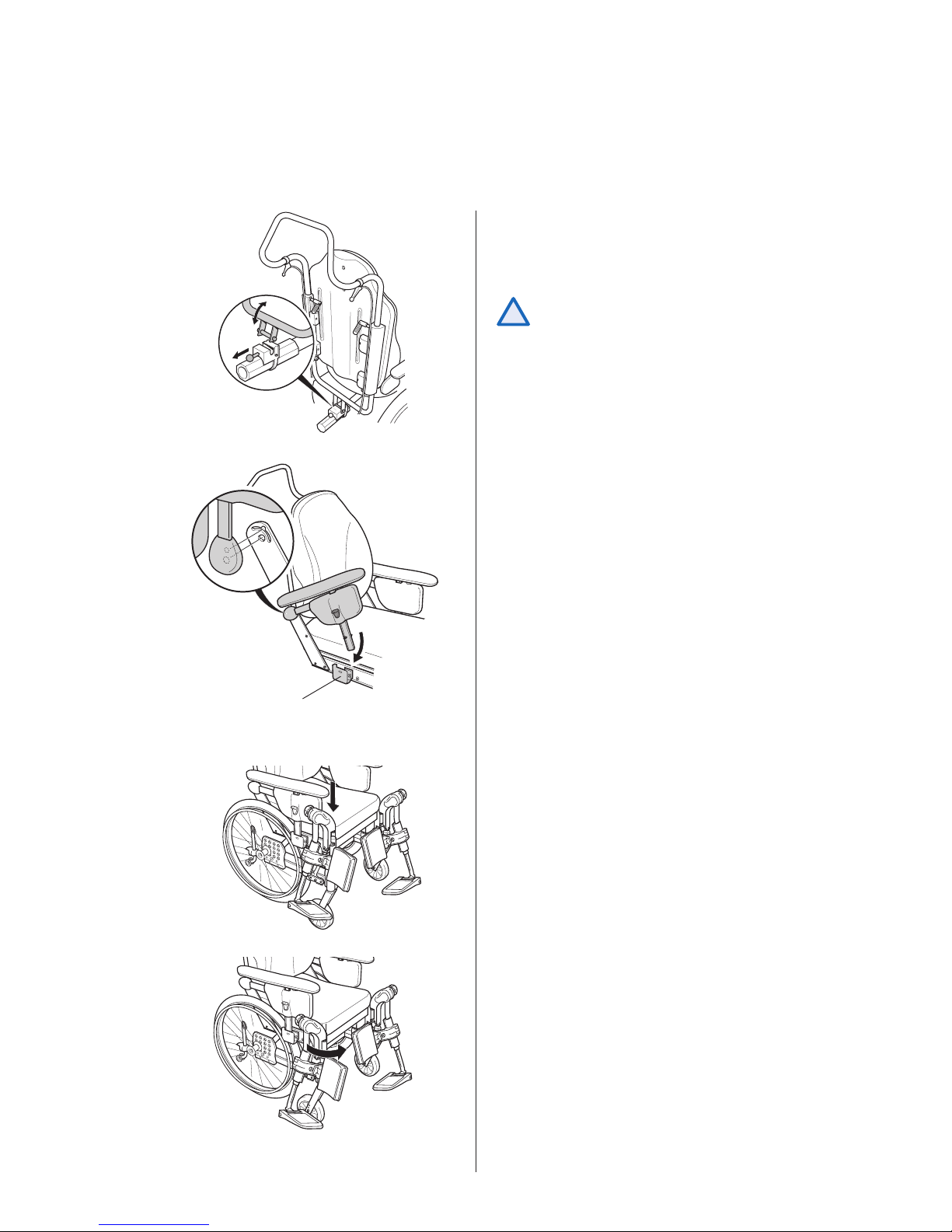
1. Backrest
The backrest is tted by angling it upwards out of
the seat and then inserting it into the attachment
as shown in the diagram.
Ensure that it “clicks” into the attachment
securely.
Assembly
2. Armrests
Fit the armrests by pushing the two tubes into the
holes on the armrest holder. The armrest is then
pushed down into the attachment (A).
3. Legrests/footrests
The wheelchair can be equipped with either
legrests or footrests.
3a Legrests
Attach the legrests by pushing the tube at the upper
part of the legrests down into the tubes on the
wheelchair. You must angle the legrests outwards
when inserting them.
!
Lock the legrests by turning them inwards. The
legrests are automatically locked so there is no
risk of them coming off the wheelchair.

REA® BELLIS
8
REA® BELLIS
9
3b.
4.
D
C
B
4. Rear wheel
The rear wheel is tted by pressing button (B)
in the middle of the hub and keeping it pressed
in whilst inserting the axle into the rear wheel
attachment (C). It is important that the wheel is
tted into place correctly and that the lock catch
(D) really has locked the wheel securely.
It is very important that you check that
the locking pin has actually locked the
wheel into position when the centre
button has been released. Take hold of the
wheels and try to detach them. This should
NOT be possible.
!
3b Footrests
Attach the footrests by pushing the tube at the
upper part of the footrests down into the tubes
on the wheelchair. You must angle the footrests
outwards when inserting them.
Lock the footrests by turning them inwards. The
footrests are automatically locked so there is no
risk of them coming off the wheelchair.
REA® BELLIS
9
A
1.
2.
3.
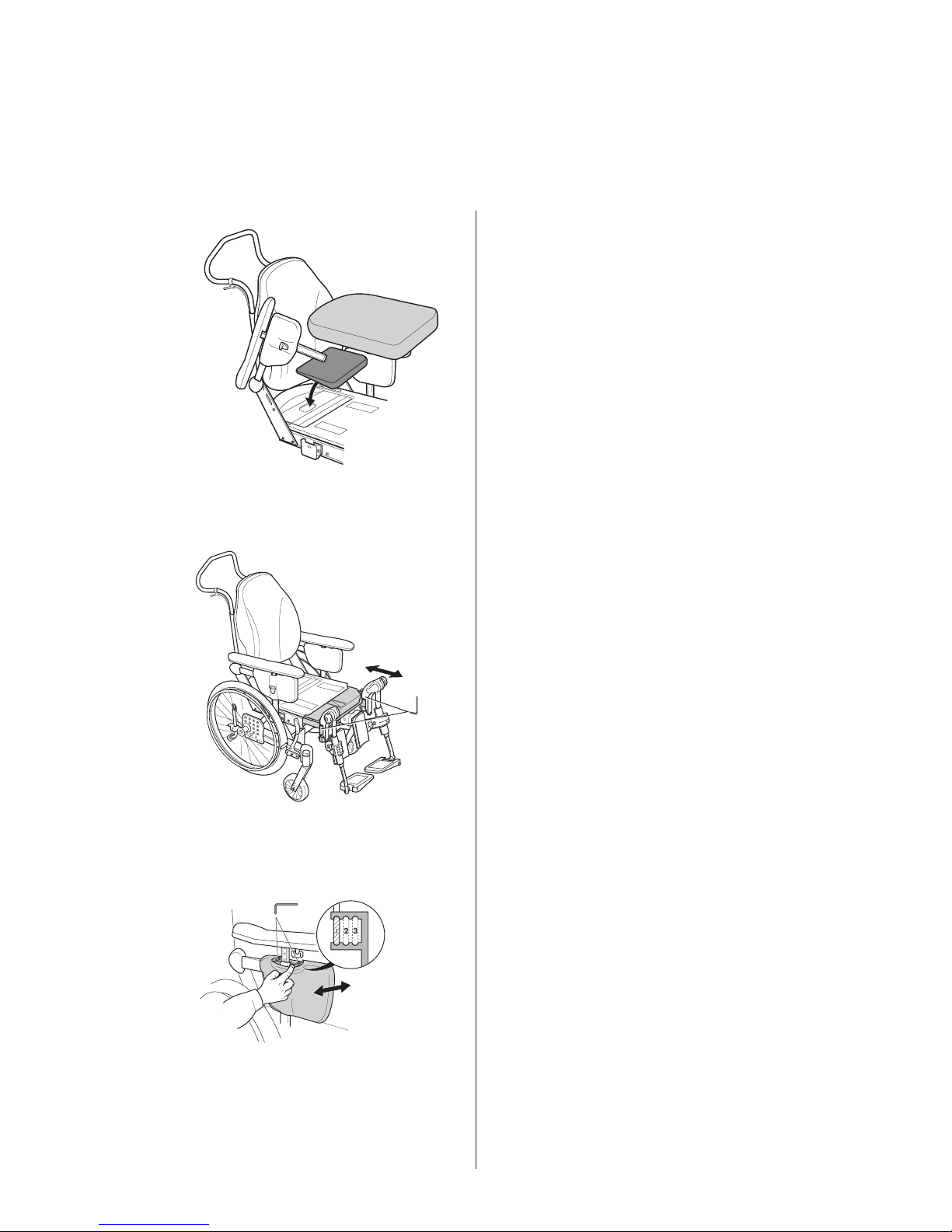
1. Seat plate
The Rea Bellis has an anatomically designed seat
plate to provide proper stability and very good
seating comfort.
Adjustments
SEAT
2. Seat depth
Loosen the two screws at the legrest attachment
with a 5-mm Allen key and adjust the seat depth to
the desired position. Then retighten the screws.
3. Seat width
The width of the seat is adjusted by moving the side
supports. Pull the upholstery carefully to one side.
Loosen the two screws (A) with a 4-mm Allen key
and move the side supports to the desired position. There are three positions: position 1 creates
a narrower chair and position 3 creates a wider
chair.
Tools: 4 mm Allen Key
Tools: 5 mm Allen Key
 Loading...