

Invacare rea Azalea Assist, rea Azalea, rea Azalea Tall, rea Azalea Minor User Manual
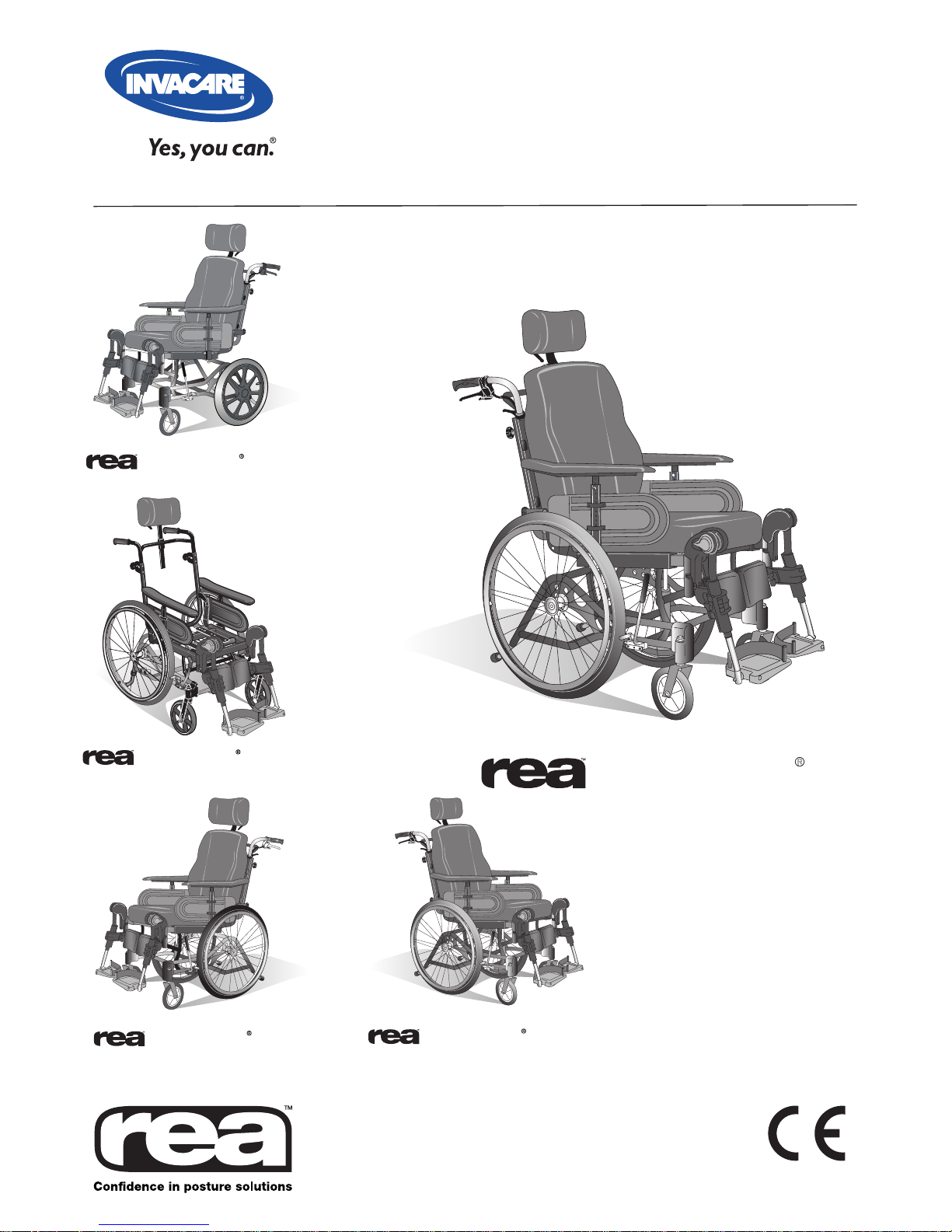
Azalea
R
Assist
Azalea
R
Base
Azalea
R
Tall
Azalea
R
Minor
Azalea
R
User Manual
English

2
Azalea
R

3
Azalea
R
Contents
Product description 3
NB ! 4
Daily performance check 4
Intended use 6
Parts of the wheelchair 7
Lifting the wheelchair 7
Standard equipment 8
Upholstery and frame colours 8
Accessories 8
Technical data 9
Delivery check 10
Assembly 10
Adjustments
Seat 12
Sliding seat 13
Legrests/footrests 13
Footplates/calf pads 14
Central legrest 15
Backrest 16
Armrests 18
Seat unit
- User and carer-operated chair 18
- Electrically operated chair 19
Charging the battery 19
Rear wheels 20
Wheelchair heights 22
Brakes 23
Carer-operated brake 23
Push handles/push bar 24
Anti-tip devices 25
Azalea Base 26
Accessories
Headrest 27
Neckrest 28
Abduction cushion 29
Trunk support 29
Pelvic belt 31
Harness 31
Transport 32
Observations 34
Restraint methods 35
Transport of wheelchairs in vehicles 36
Safety instructions/propelling techniques 37
Guarantee 39
Recycling 40

4
Azalea
R
NB!
This symbol means warning.
Below you will find a number of points affecting your personal safety. Read
them carefully!
Invacare is only responsible for product changes carried out by personnel
who we authorise. We reserve the right to make any changes to equipment
and specifications without prior notice.
Failure to comply with instructions given may result in personal injury and/or
product damage.
• Check each of the following before using the wheelchair:
– that all parts are attached securely to the frame
– that all wheels, knobs, scews and nuts are properly tightened
– that all brakes and anti-tip devices function correctly
• Never lift the wheelchair by the detachable armrests, footrests, backbrace
or by the adjustable push handles.
• Always apply the brake before getting into or out of the chair.
• Never stand on the footplates when getting into or out of the chair, because
of the risk of tipping.
• Changing the seat angle gives an increased risk of tipping over.
• The handrims may become hot due to friction, which may cause injury to
your hands.
• Use extensively the anti-tip device
• Remember that the effectiveness of the carer-operated brake is reduced
in wet and slippery conditions, as well as when on a slope.
• Be careful to ensure that the rearwheels are securely attached.
• There is a risk of tipping and injury if the velcro straps on the backrest
become too slack. Always check the tension.
• Surfaces of the wheelchair like frame parts or upholstery can, after long
exposure to the sun, reach temperatures over 41°C.
• When mounting accessories etc. be careful not to trap your fingers.
• There is always an increased risk of trap ping parts of your body when tilting
the wheelchair’s back and seat.
• The width of the seat should never be adjusted so much so that the inside
of the armrests press against the side of the pelvis.
Daily performance check
Check that the following parts are still currently assembled on the wheel-
chair:
• Wheels
• Backrest
• Anti-tip device
• Push handles
• Footrests

5
Azalea
R
Rea® Azalea
Rea® Azalea is a wheelchair with many adjustment options and accessories. To
ensure that you benefit as much as possible from Rea® Azalea, and in order
to do its options justice, the chair must be tested and adjusted by competent
personnel. We hope that you have also received instructions for using your
Rea® Azalea in everyday life.
This manual includes a description of the parts of the chair, simple adjustment
options, how to use the Rea® Azalea safely and how to transport it. The manual
must be read thoroughly before the chair is used.
Also included in this manual is a description of how all accessories are fitted
and slightly more advanced settings.
As the Rea® Azalea has many different components and accessories, the
appearance of the accessories you have for your chair may differ from those
shown.
The Rea® Azalea’s wheels, seat frame, legrests, push handles and certain other
components subjected to strain are made of steel. Backrest rails are made of
high quality aluminium.
Footplates and side supports are made of reinforced plastic. The seat plate is
made of wood and the backrest plate is made of wood and the upper part of
plastic. Plastic details are marked for recycling.
Seat and backrest cushions are made of polyether and the upholstery is made
of washable plush or elastic polyurethane cloth.
The Rea® Azalea is a manual wheelchair with an angle-adjustable seat unit. The
angle of the backrest unit can be adjusted independently of the seat. The seat
and backrest controls can be operated manually by the assistant or electrically
by the user or by the assistant.
The Rea® Azalea is available in three widths. The seat depth, backrest height,
armrest height, armrest depth, legrest height and legrest angle of each chair
can be adjusted. The height of the chair can also be altered.
The rear wheels are 24” or 22”, the castors are 140 mm-200 mm.
The wheels can be pneumatic or semi-solid, with or without a carer-operated
brake. 16” transport wheels, with carer-operated brake, can also be chosen.
The seat and backrest cushions are designed to provide good stability and
comfort for the user as well as good pressure distribution.
Product description

6
Azalea
R
Intended use Rea
®
Azalea General
The Rea® Azalea is a manual wheelchair, intended for users who can propel the chair to a
certain extent and operate the angle adjustment themselves, and who remain seated for long
periods. Rea® Azalea’s comfort and stability, as well as the option of adjusting the angle of the
seat unit and backrest, comprise an ideal combination for activity and comfortable rest.
Regarding both operation and adjustment of seating position, the Rea® Azalea is intended for
operation by the user or carer. However, the user must be fully aware of the effects of changes
made.
The Rea•
®
Azalea must be used with its seat and backrest pads.
Max. user weight is 135 kg. •
The service life of the chair depends on its application, the user’s degree of activity as •
well as care and maintenance.
Additional information for Rea® Azalea Minor
The Rea® Azalea Minor is intended for smaller adults and teenagers, who are passive users,
both semi-dependant and dependant.
Max user weight is 75 kg.•
Please note that the harness has to be fitted and adjusted by a trained therapist.•
Intended use Rea® Azalea Base
The Rea® Azalea Base is a part of the Azalea family that is meant as a wheelchair base for different seating systems such as individually adapted anatomic seats manufactured by different
companies.
The Rea® Azalea Base is intended for use both indoors and outdoors.
The maximum allowed weight load on the Rea® Azalea Base is 135 kg. This includes both user
and seating system.
The Azalea range is CE-marked, but since the Rea® Azalea Base is not to be considered as a
complete product and it is only when the base and the seating system have been combined
that an evaluation of the safety can be done, it rests upon the company that mounts the seating
system to perform such an evaluation.
However, if there is an agreement between Invacare and the manufacturer of the seating
system that regulates the responsibility between the companies, the product can maintain its
CE-marking. In other cases, the company mounting the seating system will be responsible for
the CE-marking or that the chair will be registered and documented as a specially made medical
technical product.
The Rea® Azalea Base has been crash tested together with the Invacare standard back and seat,
but no other combinations have been tested and Invacare can in no way predict the effect of an
accident with other configurations.
Other tests performed on the Azalea Base have also been carried out with the standard back
and seat from the Azalea range mounted.
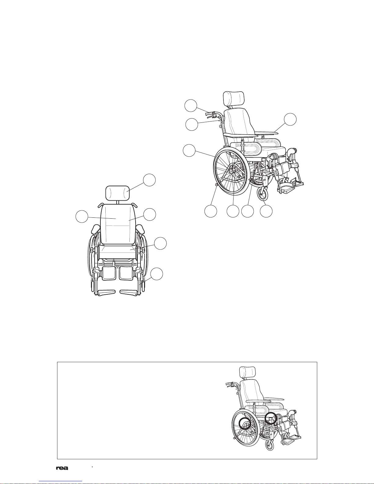
7
Azalea
R
8
6 9
4
7
12
5
10
11
3
1
13
2
1. Backrest
2. Push handle
3. Neckrest
4. Armrest
5. Rear wheel
6. Rear wheel plate
7. Anti-tip device and step tube
8. Brake
9. Castor
10. Seat
11. Legrest
12. Handle for backrest angle and seat
tilt adjustment
13. Allen key for adjustments
(on back of backrest cushion)
Always lift the wheelchair by gripping the frame
at the points shown in the diagram. Never lift
the wheelchair by the removable armrests or the
foot-rests. Ensure that the backrest and push bar
are securely in place. Also read the chapter Safety
instructions/propelling techniques.
Parts of the wheelchair
Lifting the wheelchair

8
Azalea
R
Seat width 34 - 59 cm
Seat depth 38-55 cm
Backrest height 62,5 + 20 cm without seat cushion
Standard equipment
Accessories
Backrest type
Backrest plate
Backrest tension adjustable
Backrest cushion
Laguna (lateral support)
Mistral 2 (waist support)
Passad 2 (shoulder support)
Shoulder High 05
Vicair Multifunctional
Backrest cover
Cover Thin, 04
Cover, Lateral 05
Seat
Standard
H-bracket (Azalea Base)
Seat plate (Azalea Base)
Seat cushions
Vicair Multifunctional
Flo-shape
Seat and backrest
Carer- operated recline
Electrically operated by carer/user
adjustment
Legrests
Angle adjustable
Fixed 80°, 90°
Legrest amputee
Upholstery Grey Plush, TR32
Grey Dartex, TR23
Frame colours Pearl Grey
Upholstery and frame colours
Footrests
Fixed footplate
Angle and depth adjustable
Foot plate extender
Heel strap
Armrests
Height adjustable armrest
Hemiplegic
Autolock armrest
Castors
140–200 mm, pneumatic or solid, wide or narrow
Rear wheels
16", 22", 24", pneumatic or puncture-proof
Brakes
User brake
Hand operated assistant brake
Others
Reflector Kit
Table Tray
Pump
Cane holder
Headrest
Headrest with cheek support
Neckrest
Push bar
Push handles braced
Pelvic Belt
Harness (Azalea Minor)
Trunk support
Rea® Azalea has a wide range of accessories and options. Some of the accessories may not be
available in all countries or suitable for all models.
9
Azalea
R
Technical data
Seat width
Legrest length
Weight
Seat depth
Tilt adjustment
Seat height
Total width
Transport weight
Backrest height
Total height
Backrest adjustment
Armrest height
Total length
Maximum user
weight
Azalea Azalea Assist Azalea Tall Azalea Base Azalea Minor
Seat width 39-55 cm 39-59 cm 39-59 cm 34-59 cm 34-44 cm
Seat depth 43-50 cm 43-50 cm 48-55 cm 38-50 cm 38-45 cm
Seat height 40/45 cm 40/45 cm 50 cm 40/45 cm 40/45 cm
Backrest height 50-80 cm 50-80 cm 50-80 cm - 55-65 cm
Armrest length 24-36 cm 24-36 cm 24-36 cm 24-36 cm 24-36 cm
Legrest length 33-50 cm 33-50 cm 33-50 cm 33-50 cm 33-50 cm
Tilt adjustment -1° - 20° -1° - 25° -1° - 20/25° -1° - 20/25 -1° - 20/25°
Total width sw+25 cm sw+22 cm sw+22 cm sw+22 cm sw+ 22 cm
Total height 90 - 125 cm 90 - 125 cm 100 - 130 cm 90 - 130 cm 90-125 cm
Total depth 95 - 102 cm 95 - 102 cm 95 - 107 cm 95 - 102 cm 90-97 cm
Weight 34 kg 34 kg 36 kg 20 kg 32 kg
Max user. weight 135 kg 135 kg 135 kg 135 kg 75 kg
Transport weight 16.5 kg 20.5 kg 18.7 kg 15 kg 14.5 kg
Backrest angle adjust 0° - 30° 0° - 30° 0° - 30° 0° - 30° 0° - 30°
10
Azalea
R
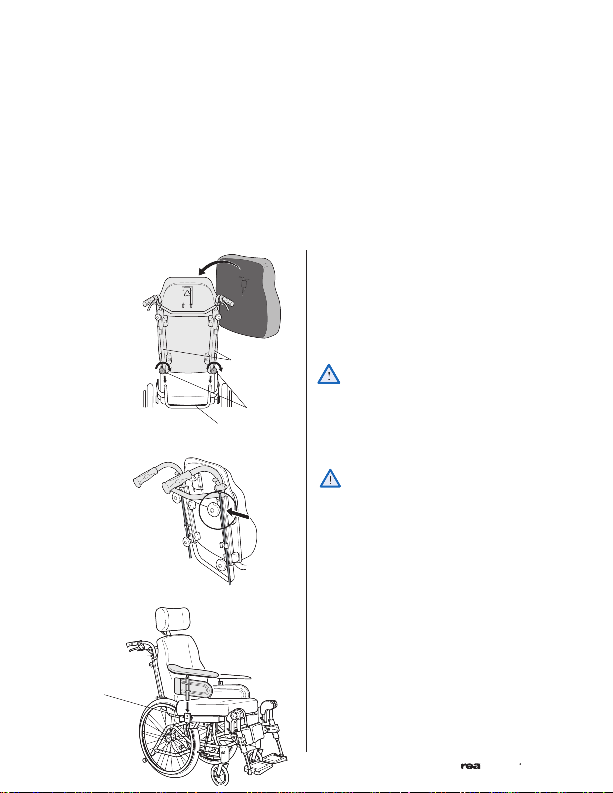
1.
2.
A
C
B
D
Assembly
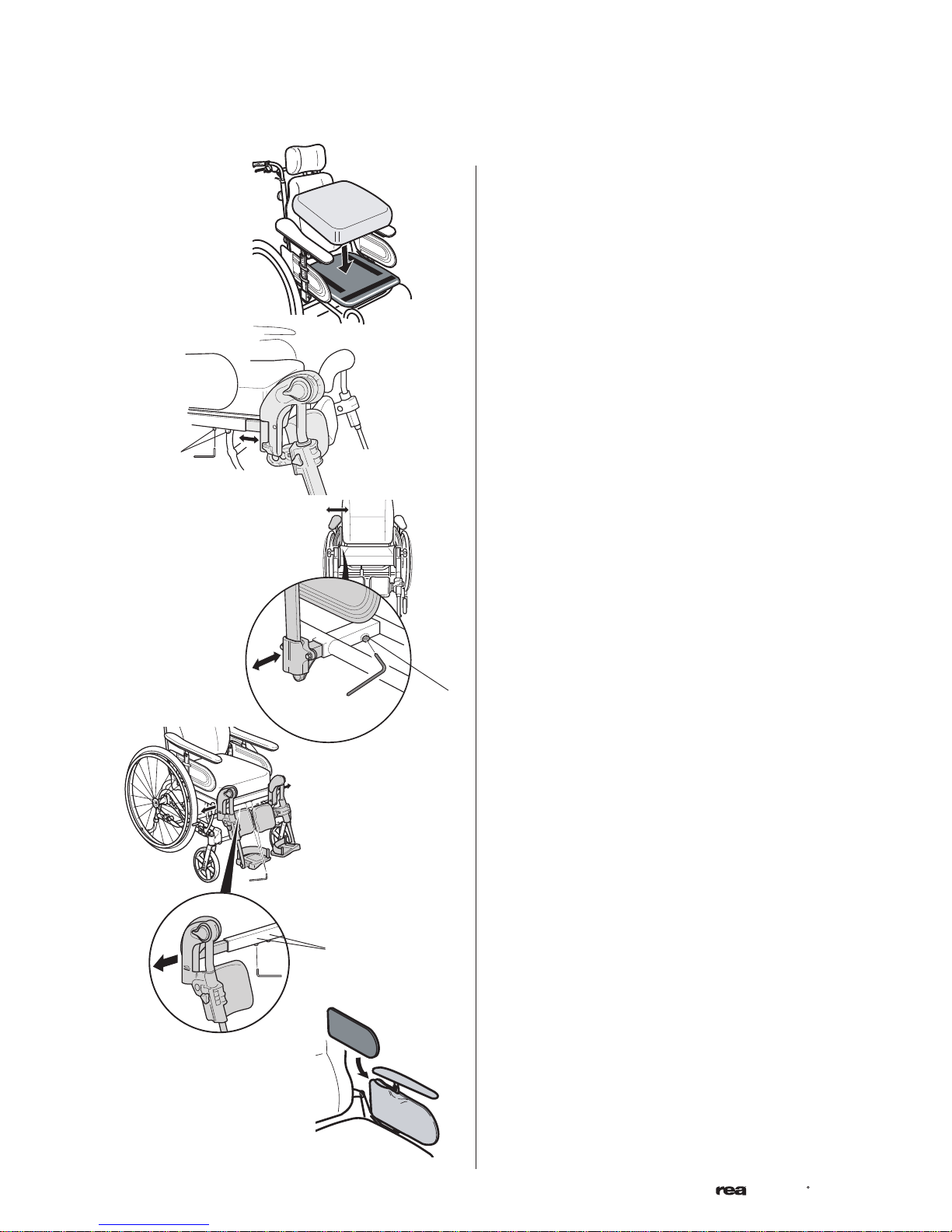
1. Backrest
The backrest is fitted onto the wheelchair by
sliding the profiles (A) of the backrest onto the
tubes of the chair (B). make sure that you push
the backrest down as far as possible. Secure into
place by tightening the knobs (C).
Secure the backrest cushion using the Velcro
strips.
Now check that the backrest is secured firmly
in position!
Delivery check
When you receive your wheelchair, you must fit the backrest, armrests and legrests onto the chair. The assembly
is simple and does not require any tools.
2. Armrests
Attach the armrests by feeding them into the
attachment (D) at the sides of the wheelchair.
Push them downwards until you can feel that the
armrests are securely in place.
When fitting the push bar/push handles be
aware to place the wires outside the handwheels. Otherwise the wires can be damaged.
Any transport damage must be reported immediately to the transport company. Remember to keep the packaging until the transport company has checked the goods and a settlement has been reached.
11
Azalea
R
4.
A
B
3b.
4. Rear wheels
Attach the rear wheels by pressing button (A)
in the centre of the hub whilst simultaneously
sliding the axle (B) into the rear wheel position
attachment of the positioning plate.
It is very important that you check that the
locking pin has actually locked the wheel into
position when the centre button has been
released. Take hold of the wheels and try to
detach them. This should NOT be possible.
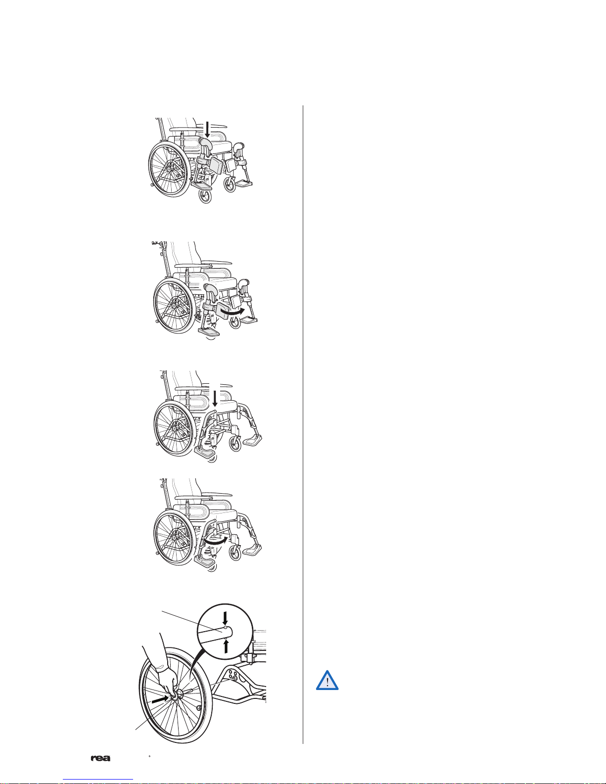
3b. Legrests fixed
Attach the footrests by pushing the tube at the
upper part of the footrests down into the tubes
on the wheelchair. You must angle the footrests
outwards when inserting them.
Lock the legrests by turning them inwards. The
legrests are automatically locked so there is no
risk of them coming off the wheelchair.
3a.
Legrests/footrests
The wheelchair can be equipped with either angle
adjustable legrests or fixed footrests.
3a. Legrests angle adjustable
Attach the legrests by pushing the tube at the
upper part of the legrests down into the tubes
on the wheelchair. You must angle the legrests
outwards when inserting them.
Lock the legrests by turning them inwards. The
legrests are automatically locked so there is no
risk of them coming off the wheelchair.
12
Azalea
R
1.
2.
3.
b.
a.
B
A
c.
C
2. Depth adjustment
Remove the seat cushion and loosen the screws (A)
with an Allen key. Move the front edge of the seat
forwards or backwards, and retighten the screws.
The distance between the back of the knee/calf
and the cushion should be as small as possible, but
without contact. Replace the seat cushion.
Tool: 5 mm Allen key
Adjustments
SEAT
3. Width adjustment
a. Loosen the screw (B) with an Allen key. Adjust
the armrests to the desired width and retighten
the screw.
b. Loosen the screws (C) with an Allen key. Adjust
the legrests to the desired width and retighten the
screws.
c. The seat width can be decreased with 2x20 mm
by placing cushions inside the aremrest pocket.
The seat depth of the chair can easily be adjusted
to provide good support. The width between the
legrests and armrests and the height of the armrests
can also be adjusted.
1. The seat cushion is secured with Velcro strips on
the seat plate.
Tool: 5 mm Allen key
Tool: 5 mm Allen key
13
Azalea
R
1.
B
A
2.
B
C
A
SLIDING SEAT (ACCESSORY)
The sliding seat is a great help to the user when
moving into or out of the chair. The user must sit in
the chair when the seat is moved forwards. Pull the
lever (A) upwards at the same time as you pull the
handle (B) and move the seat forwards.
Remember that the sliding seat increases the seat
height by about 3,5 cm. Please observe that the sliding seat is not compatible with the Tall-kit for long
users.
When you adjust the seat only use the handle.
The tip risk increases when the seat is slided
forward.
Angle adjustable legrests support the legs and reduce
pressure. The legrests can be used for bandaged legs,
but not for legs in plaster casts. The legrests must
always be fitted with calf pads, footplates and heel
straps.
It is important to adjust the height and angle of the
legrests to obtain a good seating position.
1. Height adjustment
Loosen screw (A) with an Allen key. Adjust the
legrest into a suitable height and the screw is
caught by one of the recesses on the legrest tube.
Then retighten the screw.
2. Angle adjustment
Pull the lever (B) with one hand while support-
ing the legrest with your other hand. When a
suitable angle is obtained, let go of the lever and
the legrest will look into one of seven preset
positions (C).
Do not place anything heavy, or let children
sit on the legrest. It may cause damage to the
mechanism.
The distance between the lowest part of
the footrest and the ground must be at least
40 mm.
ANGLE ADJUSTABLE LEGRESTS
Tools: 5 mm Allen Key
14
Azalea
R
2.
1.
A
C
A
C
D
B
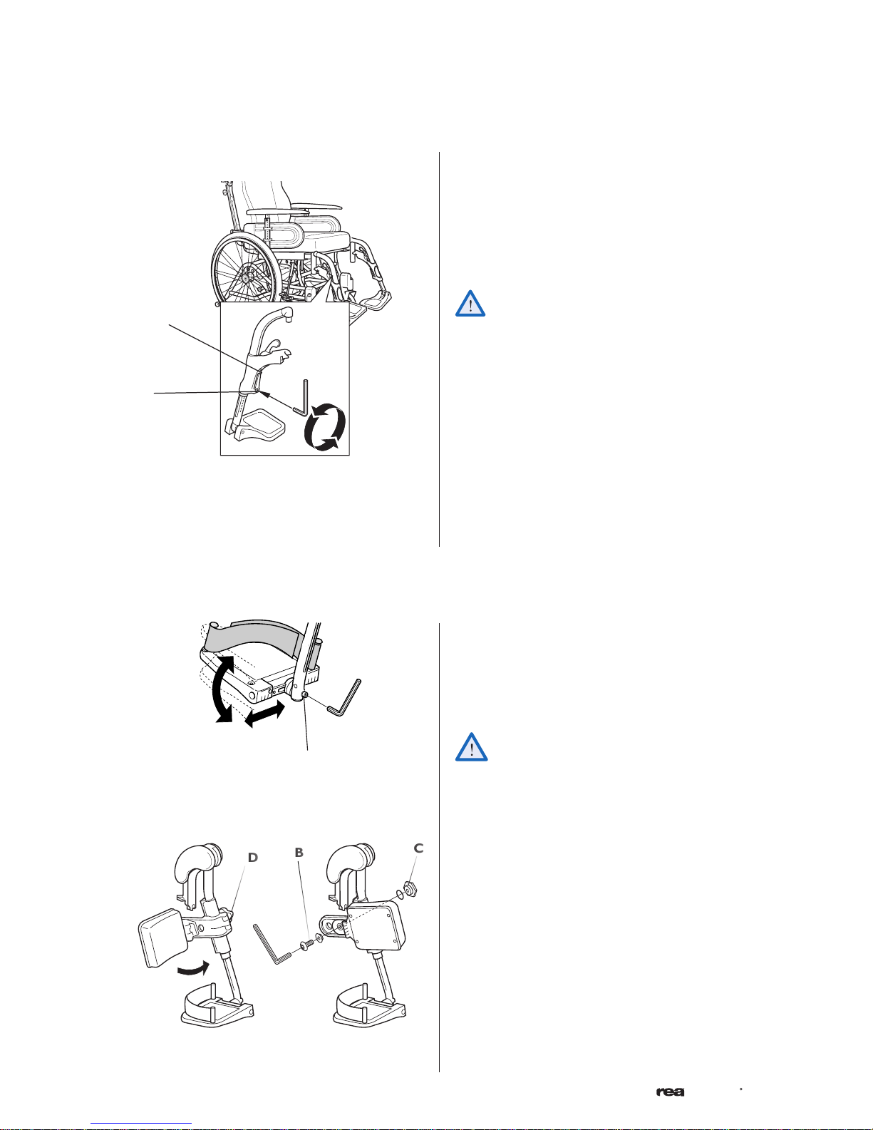
1. Angle-adjustable footplates
Adjust the angle and the depth by loosening the
screw (A) at the footplate attachment with a 5
mm Allen key. Adjust the footplate to the correct
position and retighten the screw.
Do not place anything on the footplate when
the screw is loose.
FOOTPLATE/CALFPAD
Tool: 5 mm Allen key
2. Calf pads
The calf pads can be fitted in four different depth
positions. Swing the pad forwards. Unscrew screw
(B) using an Allen key. Remove the large nut (C) on
the reverse side and place it in the other attachment hole. Move the calf pad to the new position
and secure it into place with the screw.
The height of the calf pads can easily be adjusted
using the handwheel (D).
Tool: 5 mm Allen key
Tool: 5 mm Allen key
Height adjustment
Loosen screw (A) with an Allen key. Adjust the
legrest into a suitable height and the screw is caught
by one of the recesses on the legrest tube. Then
retighten the screw.
NOTE! Don't touch the upper screw (C).
The distance between the lowest part of
the footrest and the ground must be at least
40 mm.
FIXED LEGRESTS
 Loading...