

Invacare rea Azalea Assist, Rea Azalea, rea Azalea Tall, Rea Azalea Minor User Manual
Assist
Manual
English
Base
Tall
Minor
Max

©Invacare Rea AB
Every effort has been made to ensure that the contents of
this publication are updated at the time of printing. As part of
the ongoing improvement of the products, Invacare Rea AB
reserves the right to modify existing models at any time.
Any use of this publication, or parts thereof, as well as any
reproduction of images, must have the written consent of
Invacare Rea AB
2
Azalea
R

CONTENTS
1. GENERAL 4
1.1 Introduction 4
1.2 Symbols 4
1.3 Warranty 4
1.4 Limitation of liability 4
1.5 Copyright protection 4
1.6 Customer service 4
1.7 Accidents/near accident 4
1.8 Testing 4
1.9 Intended use 5
2. SAFETY 6
2.1 Lifting The Wheelchair 6
2.2 Daily performance check 6
2.3 Specific risks 6
3. TECHNICAL DATA 7
3.1 Dimensions and weight 7
3.2 Upholstery and frame colours 8
3.3 Equipment and accessories 8
3.4 Seat height table 9
3.5 Identification label 10
4. SET-UP AND INSTALLATION 11
4.1 Delivery check 11
4.2 Wheelchair overview 11
4.3 Assembly 11
5. COMPONENTS AND ADJUSTMENTS
13
5.1 Backrest 13
5.2 Backrest för azalea max 14
5.3 Angle settings 15
5.4 Carer-operated angle adjustment 15
5.5 Electric tilt /backrest angle adjustment 16
5.6 Armrests 17
5.7 Seat 18
5.8 Legrests 19
5.9 Foot plate/calf pad/ foot rest 21
5.10 Push handles/push bar/push bar 24
5.11 Rear wheels 25
5.12 Brakes 27
5.13 Anti-tip devices 28
5.14 Azalea base 29
5.15 Accessories 30
7. TRANSPORT 37
7.1 Transporting wheelchairs
with users in vehicles 37
7.2 Restraint methods 39
7.3 How to disassemble your
Azalea® 40
8. MAINTENANCE 42
8.1 Safety Information 42
8.2 Maintenance schedule 42
8.3 Cleaning 43
9. AFTER USE 44
Recycling 44
6. USING THE WHEELCHAIR 34
6.1 Move to/from the wheelchair 34
6.2 Stretching and leaning 34
6.3 Propelling up a slope 34
6.4 Propelling down a slope 35
6.5 Climbing a kerb 35
6.6 Kerbs – alternative method 36
6.7 Escalators and stairs 36
Azalea
R
3
1. General
1.1 INTRODUCTION
Rea® Azalea is a wheelchair with many adjustment
possibilities and accessories. To ensure that you
benefit as much as possible from Rea® Azalea, and
in order to do its options justice, the chair must be
tested and adjusted by competent personnel. We
hope that you have also received instructions for
using your Rea® Azalea in everyday life.
This manual includes a description of the parts of the
chair, simple adjustment options, how to use the Rea®
Azalea safely and how to transport it. The manual must
be read thoroughly before the wheelchair is used.
Also included in this manual is a description of how
accessories are fitted and slightly more advanced
settings.
As the Rea® Azalea has many different components
and accessories, the appearance of the accessories you
have for your chair may differ from those shown.
1.2 SYMBOLS
1.4 LIMITATION OF LIABILITY
Invacare Rea AB accepts no liability for damage arising
from:
Non-compliance with the User Manual •
Incorrect use•
Natural wear and tear•
Incorrect assembly or set-up by the purchaser or •
a third party
Technical modifications•
Unauthorised modifications and/or use of unsui-•
table spare parts
The written authorisation of Invacare Rea AB must
be obtained before installing additional adaptations
on a Invacare Rea wheelchair. Otherwise no liability
claims can be made.
1.5 COPYRIGHT PROTECTION
All information quoted is believed to be correct at
time of print. Invacare® reserves the right to alter
product specifications without prior consultation. Rea,
Rea design and DSS (Dual Stability System) design are
registered trademarks of Invacare® International.
This symbol means warning and is used
for important information to prevent
injuries and material damage
1.3 WARRANTY
We provide a two-year guarantee from the delivery
date. Damage due to wear and tear on upholstery,
tyres, (rubber) tubes, hand rims and castors etc., is not
covered by the guarantee. Damage that has been caused
through physical violence or abnormal use is not covered. Damage caused by users who weigh more than
the maximum user weight stated for each Rea Azalea
model is not covered. The guarantee will only apply
if the maintenance instructions are followed.
1.6 CUSTOMER SERVICE
For contact details please refer to the last page of
this publication where you will find addresses to the
european sales companies.
1.7 ACCIDENTS/NEAR ACCIDENT
Please inform your Invacare office immediately of any
accidents or near-accidents that have been caused by
this wheelchair and that have led to, or could have
led to, personal injury. The relevant authority must
also be contacted and reported to.
1.8 TESTING
The Rea
®
Azalea has been tested and approved by
TÜV and is CE-marked according to the Medical
Device Directive.
4
Azalea
R

1.9 INTENDED USE
REA AZALEA GENERAL
The Rea® Azalea is a manual wheelchair, intended
for passive users, both dependant and semi-dependant, who remain seated for long periods of time.
Regarding both operation and adjustment of seating
position, the Rea
®
Azalea is intended for operation
by the user or carer.
The Rea•
®
Azalea must be used with its seat and
backrest pads.
The Rea Azalea is intended for use both indoors •
and outdoors
Max. user weight is 135 kg. •
The service life of the chair depends on its •
application, the user’s degree of activity as
well as care and maintenance.
1.10 INTENDED USE
REA AZALEA MINOR
The Rea® Azalea Minor is intended for smaller adults
and teenagers, who are passive users, both semidependant and dependant.
Max user weight is 75 kg.•
Please note that the harness has to be fitted and •
adjusted by a trained therapist.
However, if there is an agreement between Invacare
and the manufacturer of the seating system that regulates the responsibility between the companies, the
product can maintain its CE-marking. In other cases,
the company mounting the seating system will be
responsible for the CE-marking or that the chair will
be registered and documented as a specially made
medical technical product.
®
The Rea
Azalea Base has been crash tested together
with the Invacare standard back and seat, but no
other combinations have been tested and Invacare
can in no way predict the effect of an accident with
other configurations.
Other tests performed on the Azalea Base have also
been carried out with the standard back and seat
from the Azalea range mounted.
1.12 INTENDED USE
REA AZALEA MAX
The Rea
®
Azalea Max is intended for larger adults
who are passive users, both semi-dependant and
dependant.
Max user weight is 180 kg.•
1.11 INTENDED USE
REA AZALEA BASE
The Rea® Azalea Base is a part of the Azalea family
that is meant as a wheelchair base for different seating systems such as individually adapted anatomic
seats manufactured by different companies.
The Rea
®
Azalea Base is intended for use both indo-
ors and outdoors.
The maximum allowed weight load on the Rea
®
Azalea Base is 135 kg. This includes both user and
seating system.
The Azalea range is CE-marked, but since the Rea
®
Azalea Base is not to be considered as a complete
product and it is only when the base and the seating
system have been combined that an evaluation of the
safety can be done, it rests upon the company that
mounts the seating system to perform such an evaluation.
1.13 SERVICE LIFE
We estimate that the Invacare® wheelchair has a
service life span of five years. It is difficult to state the
exact length of the service life of our products and the
length stated is an estimated average life span based on
normal use. The life span may be considerably longer
if the wheelchair is used to a limited extent and if it is
used with care, maintained and handled properly. The
life span may be shorter if the wheelchair is subjected
to extreme use.
Azalea
R
5
2. Safety
2.1 LIFTING THE WHEELCHAIR
Always lift the wheelchair by grabbing the frame at
the points shown in the picture.
Never lift the wheelchair by the removable armrests
or the footrests. Ensure that the backrest and push
handles are securely in place. Also read the chapter
Safety instructions/Propelling techniques.
2.2 DAILY PERFORMANCE CHECK
Check that the following parts are correctly mounted
on the wheelchair:
• Wheels
• Backrest
• Anti-tip device
• Push handles
• Footrests
2.3 SPECIFIC RISKS
Below you will find a number of points affecting your
personal safety. Read them carefully!
Invacare is only responsible for product changes carried out by competent personnel. We reserve the
right to make any changes to equipment and specifications without prior notice.
Failure to comply with instructions given may result
in personal injury and/or product damage.
• Check each of the following before using the
wheelchair:
– that all parts are attached securely to the
frame
– that all wheels, knobs, scews and nuts are
properly tightened
– that all brakes and anti-tip devices function
correctly
• Never lift the wheelchair by the detachable arm-
rests, footrests, backbrace or by the adjustable
push handles.
• Always apply the brake before getting into or out
of the chair.
• Never stand on the footplates when getting into or
out of the chair, because of the risk of tipping.
• Changing the seat angle can mean an increased risk
of tipping over.
• The handrims may become hot due to friction,
which may cause injury to your hands.
• Use the anti-tip device
• Remember that the effectiveness of the carer-
operated brake is reduced in wet and slippery
conditions, as well as when on a slope.
• Be careful to ensure that the rearwheels are
securely attached.
• There is a risk of tipping and injury if the velcro
straps on the backrest become too slack. Always
check the tension.
• Surfaces of the wheelchair like frame parts or
upholstery can, after long exposure to the sun,
reach temperatures over 41°C.
• When mounting accessories etc. be careful not to
trap your fingers.
• There is always an increased risk of trap ping parts
of your body when tilting the wheelchair’s back
and seat.
• The width of the seat should never be adjusted
so much so that the inside of the armrests press
against the side of the pelvis.
6
Azalea
R
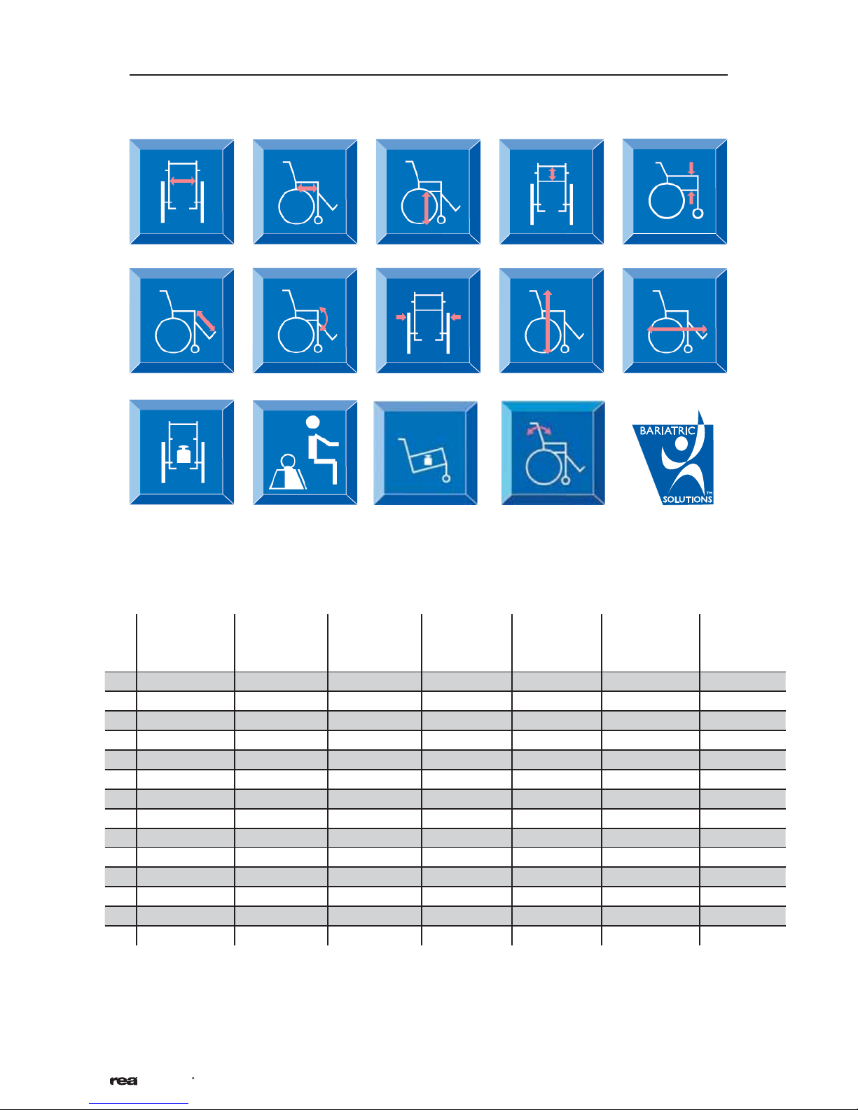
3.1 DIMENSIONS AND WEIGHT
3. Technical data
1. Seat width
6. Legrest length
11. Weight 13. Transport
AZALEA AZALEA
2. Seat depth
7. Tilt adjustment
12. Maximum user
weight
ASSIST
AZALEA
TALL
3. Seat height*
8. Total width**
weight***
AZALEA
BASE
4. Backrest height
9. Total height
14. Backrest adjustment
AZALEA
MINOR
AZALEA
MAX
5. Armrest height
10. Total length
AZALEA
MAX
ASSIST
1. 39-55 CM 39-59 CM 39-59 CM 34-59 CM 34-44 CM 55-71 CM 55-71 CM
2. 43-50 CM 43-50 CM 48-55 CM 38-50 CM 38-45 CM 53-60 CM 53-60 CM
3. 40/45 CM 40/45 CM 50 CM 40/45 CM 40/45 CM 40/45 CM 40/45 CM
4. 50-80 CM 50-80 CM 50-80 CM - 55-65 CM 50 CM 50 CM
5. 24-36 CM 24-36 CM 24-36 CM 24-36 CM 24-36 CM 32-42 CM 32-42 CM
6. 33-50 CM 33-50 CM 33-50 CM 33-50 CM 33-50 CM 33-50 CM 33-50 CM
7. -1° - 20° -1° - 25° -1° - 20/25° -1° - 20/25 -1° - 20/25° 1°-20° 1°-20°
8. SW+25 CM SW+22 CM SW+22 CM SW+22 CM SW+ 22 CM SW+25 CM SW+22 CM
9. 90 - 125 CM 90 - 125 CM 100 - 130 CM 90 - 130 CM 90-125 CM 102-124 CM 102-124 CM
10. 95 - 102 CM 95 - 102 CM 95 - 107 CM 95 - 102 CM 90-97 CM 105-112 CM 105-112 CM
11. 34 KG 34 KG 36 KG 20 KG 32 KG 54 KG 54 KG
12. 135 KG 135 KG 135 KG 135 KG 75 KG 180 KG 180 KG
13. 16.5 KG 20.5 KG 18.7 KG 15 KG 14.5 KG 26 KG 30 KG
14. 0° - 30° 0° - 30° 0° - 30° 0° - 30° 0° - 30° 0° - 30° 0° - 30°
Azalea
R
7

3.2 UPHOLSTERY AND FRAME COLOURS
Upholstery
Grey Plush TR32
Grey Dartex TR23
Frame colour
Pearl Grey
3.3 EQUIPMENT AND ACCESSORIES
Invacare® Rea Azalea has a wide range of accessories and options. Some of
the accessories may not be available in all markets or on all models.
Backrest
Tension adjustable
Backrest plate
Backrest cover/cushion
Thin plush cover
Lateral cover
Laguna (lateral support) cushion
Mistral 2 (waist support) cushion
Passad 2 (shoulder support) cushion
Shoulder High 05 (dartex) cushion
Vicair multifunctional cushion
Seat
Depth adjustable
Sliding seat
Seat cushions
Floshape
Vicair Multifunctional
Visco top
Seat and backrest regulation
Assistant operated gas piston seat and backrest tilt
Electrical operated seat and backrest tilt
Legrests
Central legrest
Angle adjustable
Fixed 80° or 90°
Amputee legrest
Rear wheels
16”, 22", 24", pneumatic,puncture-proof or
solid
Brake
User-brake
Carer-operated drumbrake
Others
Headrest
Headrest with cheek support
Neckrest
Trunk support
Lumbar support
Wedges
Pelvic belt
Harness
Reflectors
Table tray
Pump
Cane holder
Push bar
Braced push handles
Several types of handrims
Spoke guard
Footplates
One piece footrest
Fixed
Depth and angle adjustable
Footboard converter
Armrests
Height adjustable with standard pad, wide pad or
extra padding
Hemiplegic armrest
Castors
140-200 mm, soft medium or pneumatic
Widths 27 -45 mm
8
Azalea
R
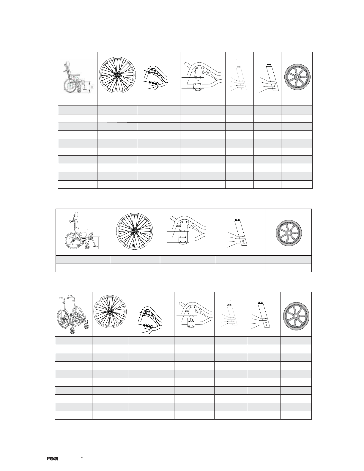
3.4 SEAT HEIGHT TABLES
3.4.1 Rea® Azalea & Rea® Azalea Assist
1
2
3
45 24" 2 1 200
45 24" 2 2 150
45 24" 2 2 140
40 22" 1 3 150
40 22" 1 3 140
40 16"
40 16" 4
45 16" 3
45 16" 3 2 150
45 16" 3 2 140
3.4.2 Rea® Azalea equipped with Tall-kit
110
4
5
4
4
3
2
1
3 150
3
1
150
4
3
2
1
140
200
150
4
5
4
3
2
1
50 24" 4 2 200
50 16" 5 3 200
3.4.3 Rea® Azalea Base
150
4
3
2
1
45
110
1
2
3
4
5
4
3
2
1
24" 2 1 200
45 24" 2 2 150
45 24" 2 2 140
40 22" 1 3 150
40 22" 1 3 140
45 16" 3 1 200
45 16" 3 2 150
45 16" 3 2 140
40 16" 4 3 150
40 16" 4 3 140
Azalea
R
9
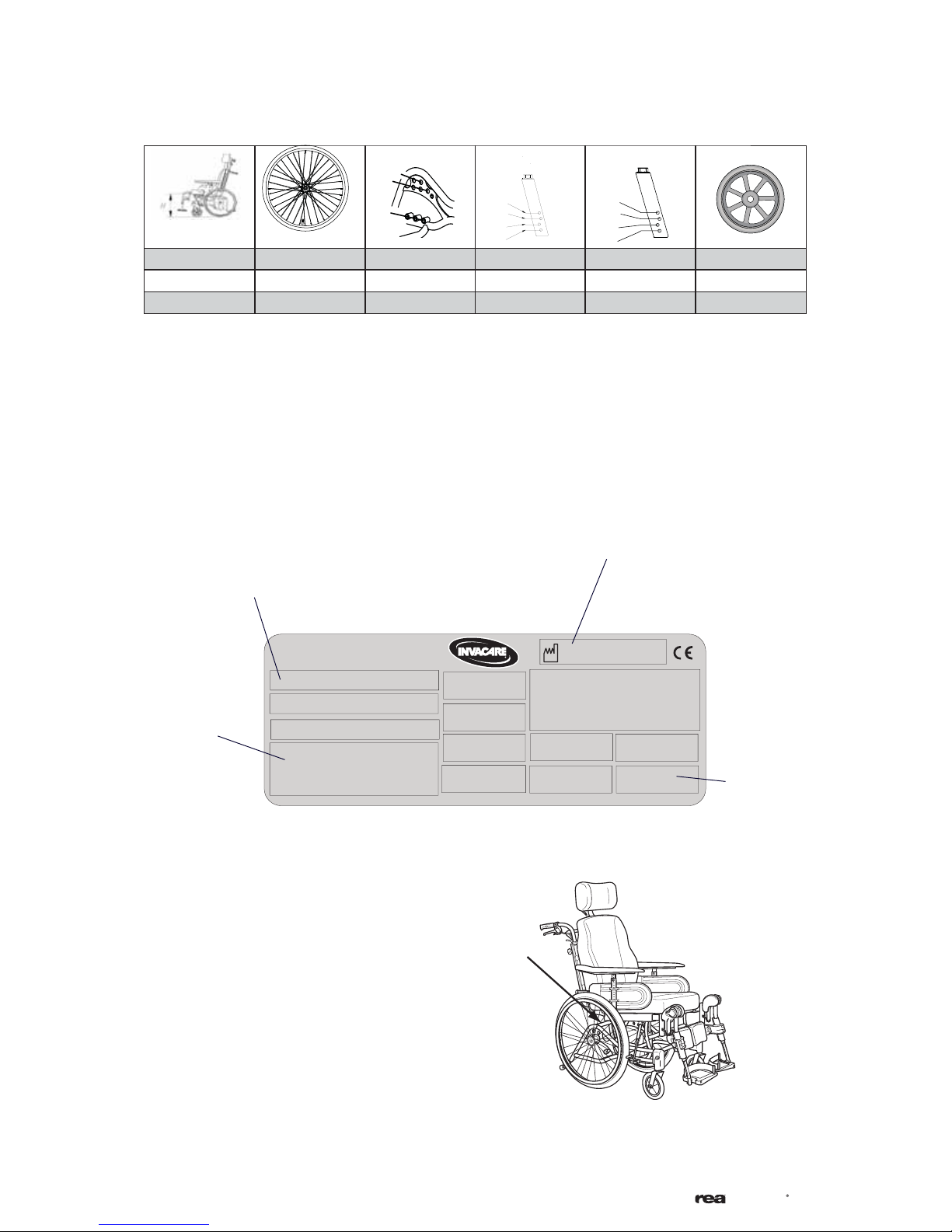
3.4.4 Rea® Azalea Max
1
2
3
110
4
3
2
1
150
4
3
2
1
45 24’’ 2 1 200
40 22’’ 1 3 140
45 16’’ 3 1 200
3.5 IDENTIFICATION LABEL
Manufacturing date
Model
Serial No.
INVACARE International SARL
Max. user weight
Location
Location of the identification label.
10
Azalea
R
4. Set-up and installation
4.1 DELIVERY CHECK
Any transport damage must be reported immediately
to the transport company. Remember to keep the
packaging until the transport company has checked
the goods and a settlement has been reached.
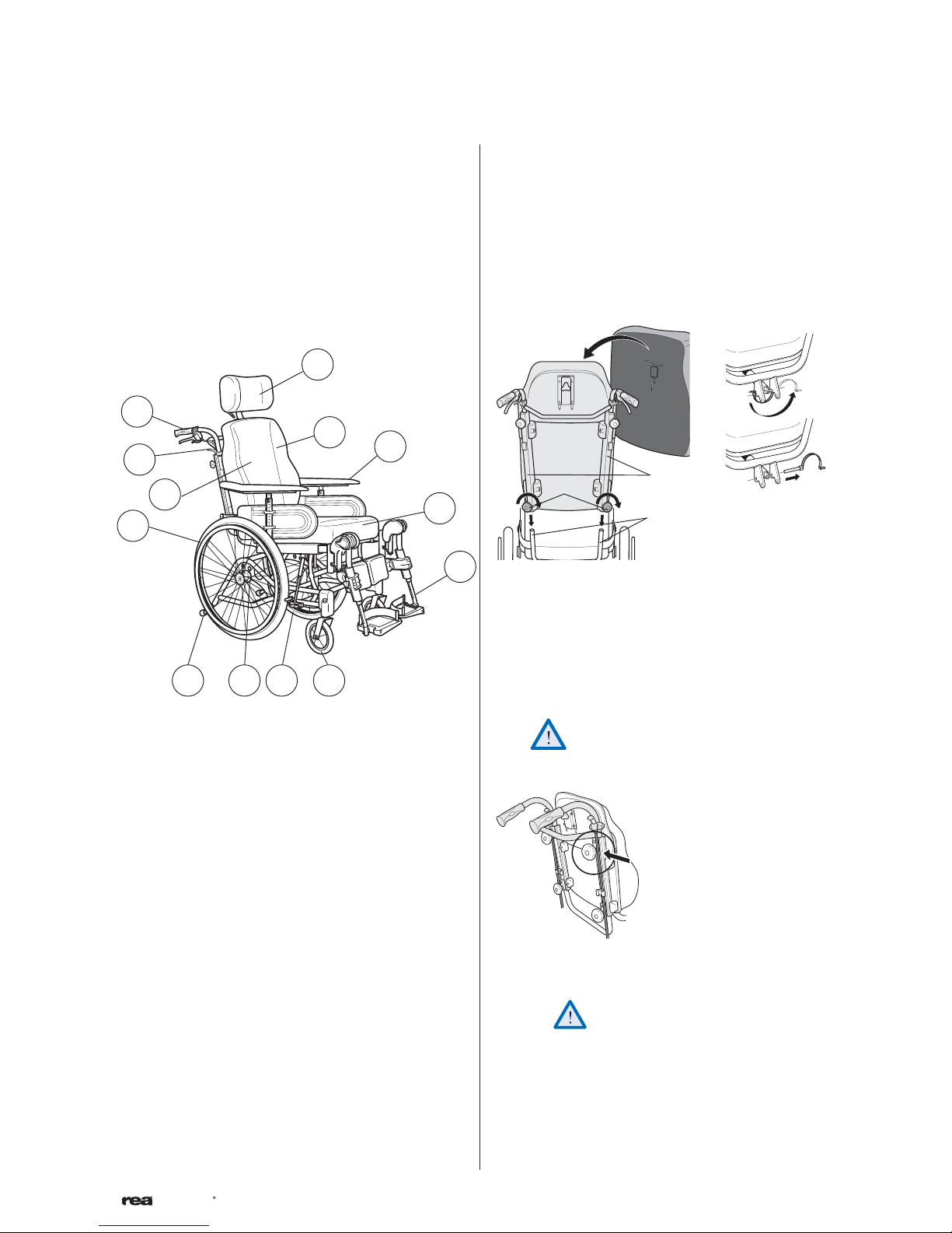
4.2 WHEELCHAIR OVERVIEW
1
13
10
12
11
2
9
78 6
3
4.3 ASSEMBLY
When you receive your wheelchair, you must fit the
backrest, armrests and legrests onto the chair. The
assembly is simple and does not require any tools.
4.3.1 Backrest
D
C
4
5
The backrest is fitted onto the wheelchair by sliding
the profiles (A) of the backrest onto the tubes of the
chair (B). make sure that you push the backrest down
as far as possible. Secure into place by tightening the
knobs (C). On the Azalea Max the pin (D) needs to
be secured at the bottom of the backrest.
Secure the backrest cushion using the Velcro strips.
A
B
1. Neckrest
2. Backrest
3. Armrest
4. Seat
5. Legrest
6. Castor
7. Brake
8. Rear wheel plate
9. Anti-tip device and step tube
10. Rear wheel
11. Allen key for adjustments (on back of backrest
cushion)
12. Handle for backrest angle and seat tilt adjustment
13. Push handle
Now check that the backrest is secured
firmly in position!
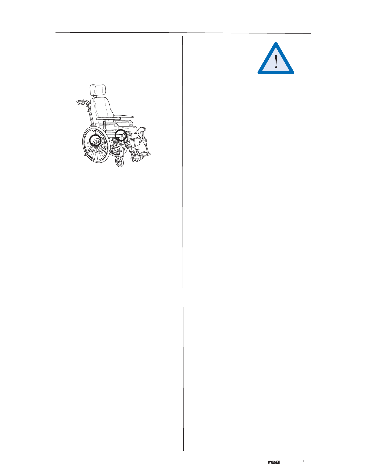
When fitting the push bar/push
handles be aware to place the wires
outside the handwheels. Otherwise
the wires can be damaged.
Azalea
R
11
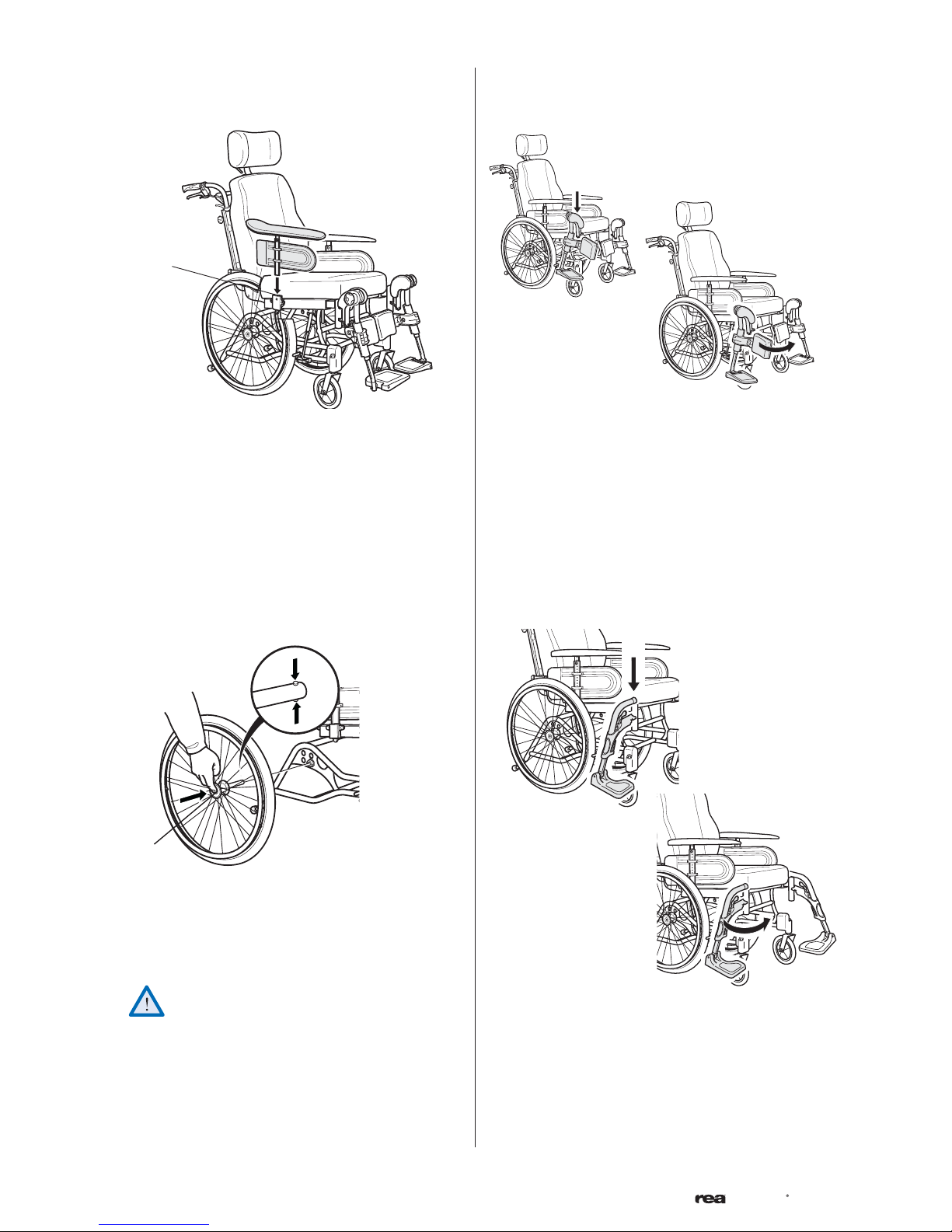
4.3.2 Armrests
D
Attach the armrests by feeding them into the attachment (D) at the sides of the wheelchair. Push them
downwards until you can feel that the armrests are
securely in place.
4.3.4 Angle adjustable legrests
Attach the legrests by pushing the tube at the upper
part of the legrests down into the tubes on the wheelchair. You must angle the legrests outwards when
inserting them.
Lock the legrests by turning them inwards. The legrests are automatically locked so there is no risk of
them coming off the wheelchair.
4.3.3 Rear wheels
A
Attach the rear wheels by pressing button (A) in the
centre of the hub whilst simultaneously sliding the
axle (B) into the rear wheel position attachment of
the positioning plate.
It is very important that you check that the
locking pin has actually locked the wheel into
position when the centre button has been
released. Take hold of the wheels and try to
detach them. This should NOT be possible.
4.3.5 Fixed legrests
Attach the footrests by pushing the tube at the upper
part of the footrests down into the tubes on the
wheelchair. You must angle the footrests outwards
when inserting them.
12
Lock the legrests by turning them inwards. The legrests are automatically locked so there is no risk of
them coming off the wheelchair.
Azalea
R
5.1 BACKREST
5. Components and their adjustments
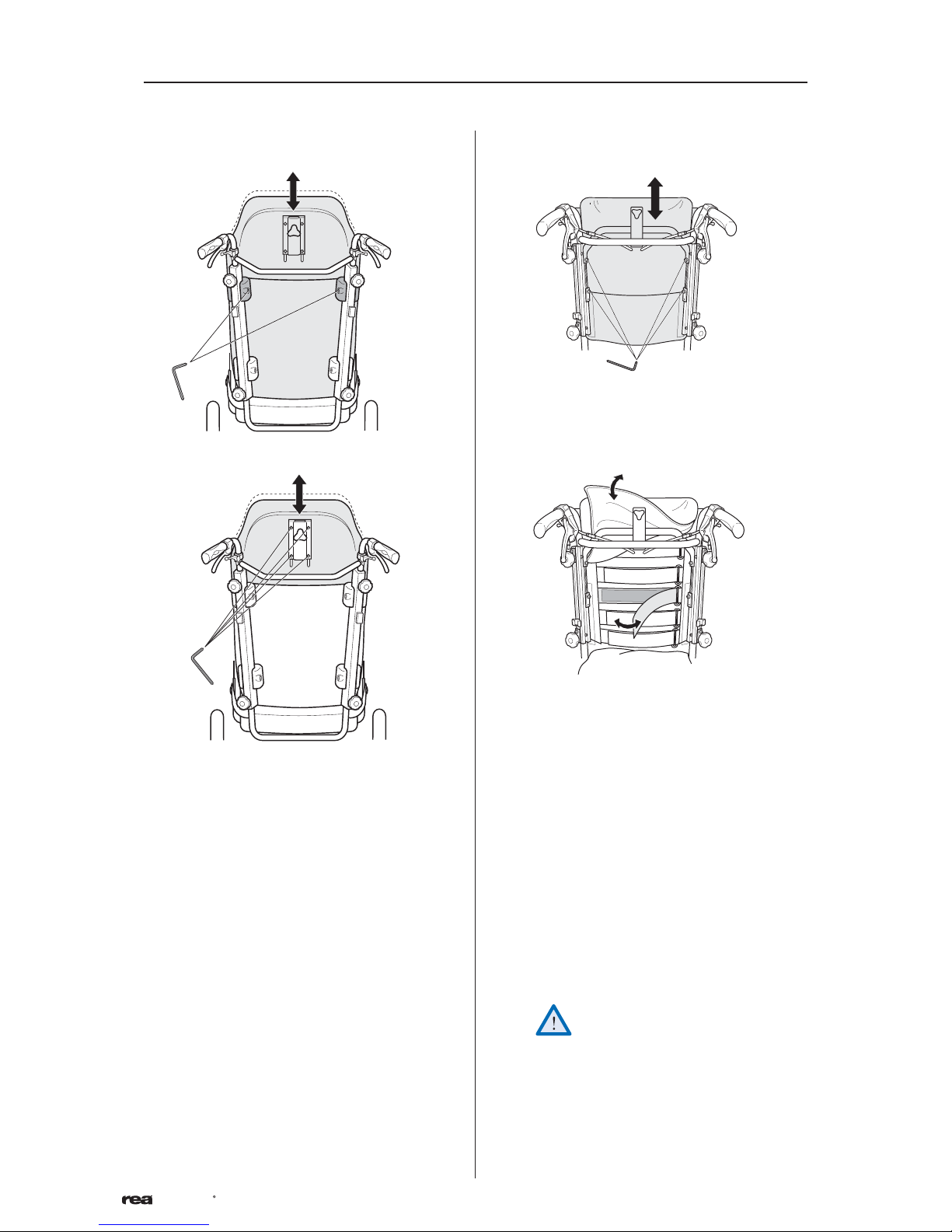
5.1.1 Backrest plate
1.
A
2.
5.1.2 Tension adjustable backrest
1.
A
2.
B
1. You can easily adjust the backrest plate (+ 10
cm) by loosening the two upper screws (A) with
a 5-mm Allen key. Set at the required height and
re-tighten.
2. The upper section has two height levels and it is
also removable (to fit lower backrest cushions).
Loose screws (B) with an 5-mm Allen key and raise
it to its highest position. For removal, remove the
screws (B).
1. For raising the height (+12,5cm), loose screw (A)
and lift the backrest frame up.
2. For shaping the form, loose the Velcro straps,
tighten first where you would like to have a firm
support and follow with the others. Check that
the cover/cushion do not "lock" the straps by the
Velco attachment.
Please ensure that the velcro straps are
not too loose, as this will result in your
back coming into contact with backrest
bow (A), and could result in injury.
Azalea
R
13
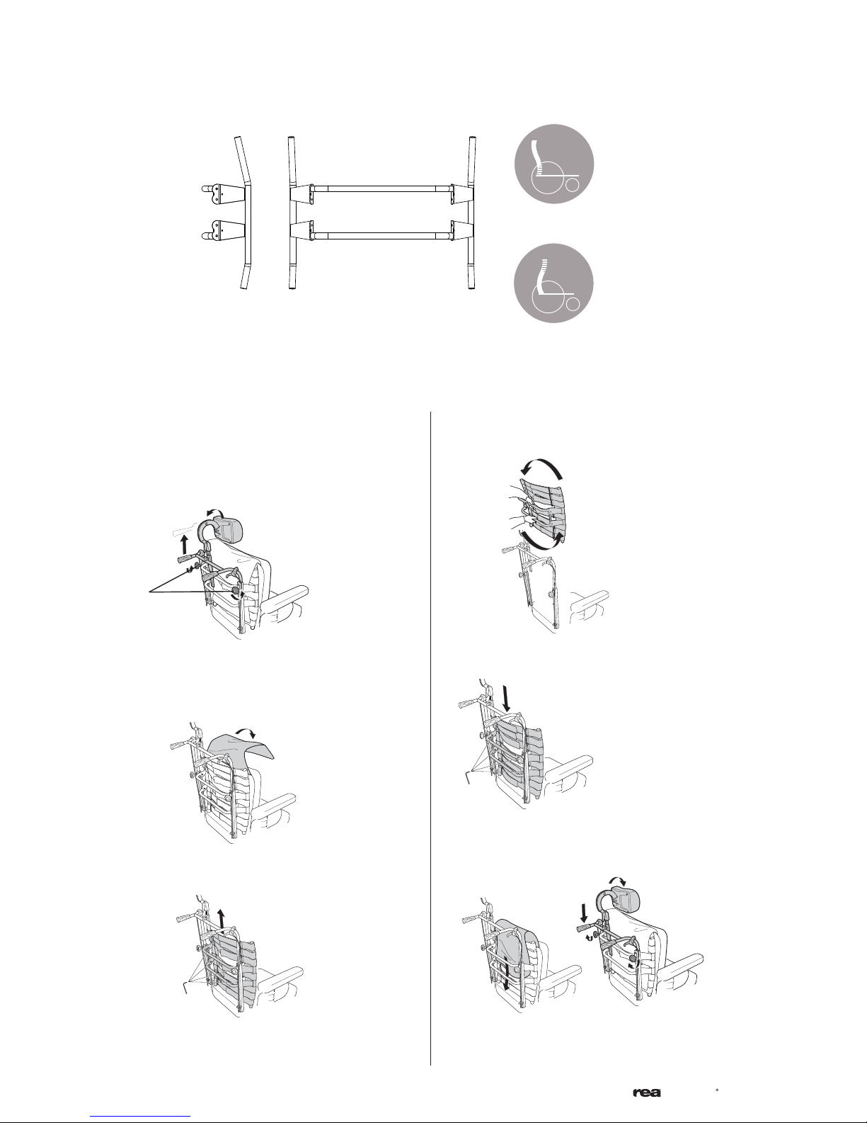
5.2 BACKREST FÖR AZALEA MAX
A
B
The backrest for the Azalea Max is designed with different angles as shown in picture 1. This allows for different
adjustments according to how the backrest is mounted. Position A (the part of the backrest with the longer
angle turned upwards) gives the user more room for the shoulder area while position B gives more room for
the bottom.
5.2.1 Adjustment
4.
1.
A
Loosen the handwheels (A) and raise the push handles
as far as possible.
2.
Remove the cushion.
3.
Turn the backrest 180°
5.
Put the backrest back by fitting it to the receivers on
the tubes. Tighten the screws.
6.
Loosen screws (B) and remove the backrest by lifting
upwards.
14
Put the cushion and cover back. Lower the push
handles and tighten the hand wheels.
Azalea
R
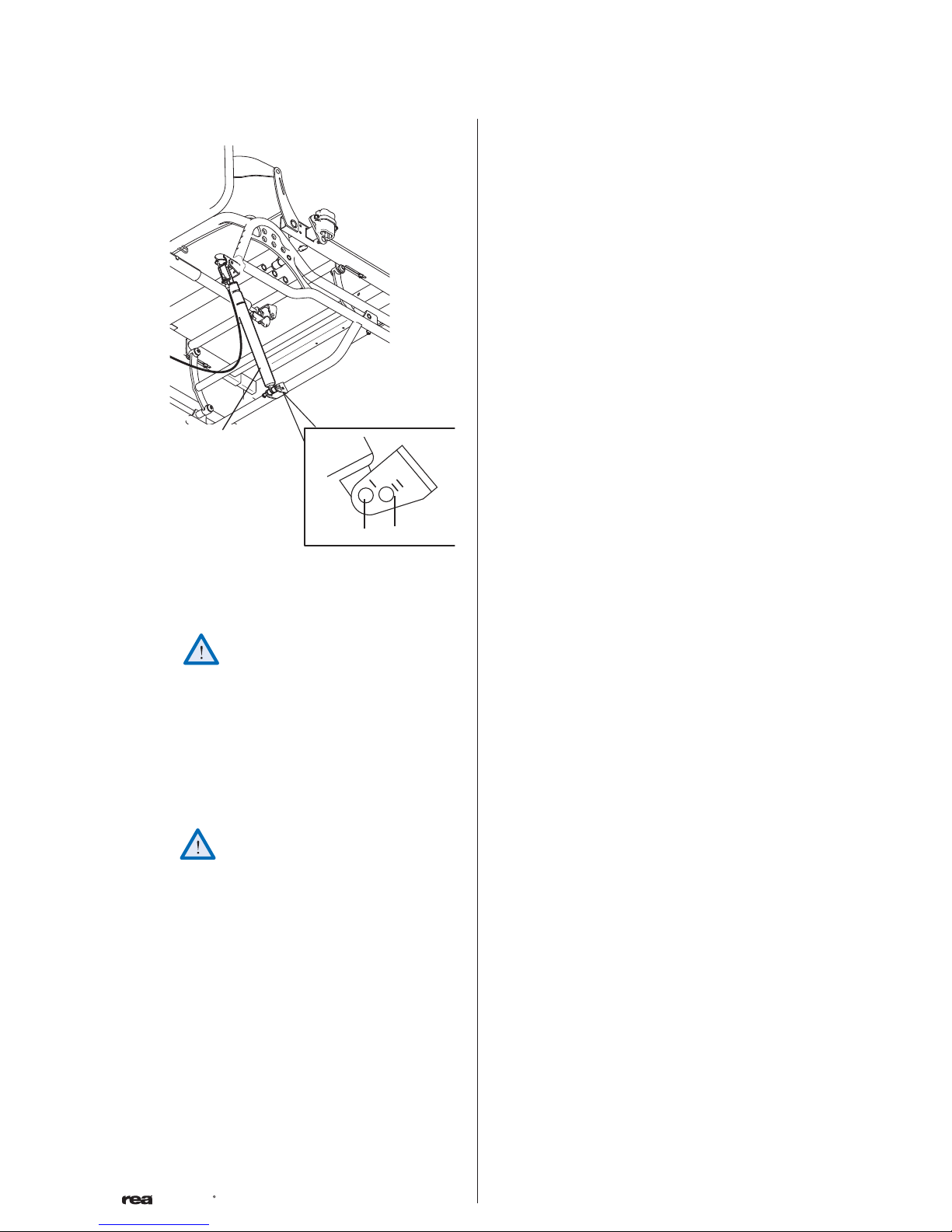
5.3 ANGLE SETTINGS
B
A
D
C
There is a possibility to change the range of available angles for the seat by changing the position of
the gas spring (A) on the chassi attachment (B).
This procedure may only be performed
by a service technician!
Azalea Max can only use hole II (D). Except for the
cases where electric tilt and angle controls are used,
then ONLY hole I (C) may be used.
Other Azalea models might use either hole. Except
for the cases where electric tilt and angle controls
are used, then ONLY hole 1 (C) may be used.
The wheelchair should be tipped
over sideways before the gas spring is
loosened from the chassi attachment.
Otherwise there is a risk of pinching.
Angles obtained:
Hole I:
16’’ rear wheels -1° - +23°
24 ‘‘ rear wheels -1° - +23°
Hole II
16’’ rear wheels +1° - +25°
24’’ rear wheels +1° - +25°
Azalea
R
15
 Loading...