

Invacare PT2000 Owner's Manual

Invacare PT2000 Powered Wheelchair
OWNERS MANUAL
INDEX
PAGE
• Introduction
2
• Commissioning Your Power Chair
3
• Unfolding Your Power Chair
4
• Fitting Your Controller – Control System
5
• Fitting Anti Tippers, Fitting Batteries
6
• Setting Armrest Height, Fitting and Leg rest Adjustment
7
• Gear Selection, Brakes
8
• Folding and Transportation – Care & Maintenance
9
• Service & Repair
9
• Battery Wiring Diagram
10
• Battery Charging, Battery Tips
11
• Electrical Troubleshooting guide & Controller Diagnostics
12 – 13
• Controller Lock Feature
14
• Driving Tips
15
• Accessories Available
16
• Warranty
17
• General Guidelines – Safety
18 – 25
• Electromagnetic Interference
26 – 27
• Safety Inspection/Troubleshooting
28 – 29
1

Thank You for Choosing to Purchase a PT2000 Powered Wheelchair
PLEASE READ THIS MANUAL
♦ Your wheelchair chair has been measured, designed & manufactured especially for YOU.
♦ With reasonable care & regular minimal maintenance we are sure your new PT2000
powered wheelchair will serve you reliably for many years.
♦ To ensure the quality of Invacare NZ product, and for your safety, all Invacare products
are built to strict standards.
♦ The PT2000 has been tested to, and passed Australian/New Zealand Standards AS
3696-1:1990, AS3696-8:1998.
♦ Not all PT2000 chairs manufactured by Invacare NZ are individually tested for
compliance with AS 3696,parts 1,2&8 and, due to customising, may be outside the
scope of some parts of that Standard. Invacare takes every care in setting up chairs to
maximise safety. Invacare cannot be responsible for the effect that non-Invacare
modifications may have upon chairs.
♦ Most Invacare products include many adjustable features. Use CAUTION when
adjustments are at extremes as stability and function may be affected. (see Driving Tips)
♦ The maximum user weight for your particular wheelchair is marked on the frame.
Exceeding this weight may alter the wheelchair’s performance and may affect your
safety.
PT2000 wheelchairs are available with a wide range of options making them suitable for
indoor and outdoor use, with user or attendant control. Some of the features described in
this manual may not apply to your particular wheelchair.
2
COMMISSIONING YOUR POWERCHAIR
Following is the recommended procedure for commissioning your power chair.
It covers the details for unfolding the Power chair, fitting the control system, the batteries,
and the leg rests, and finally placing the Power chair in gear.
Should it become necessary to fold your Power chair for transportation or storage? (See
page 8)
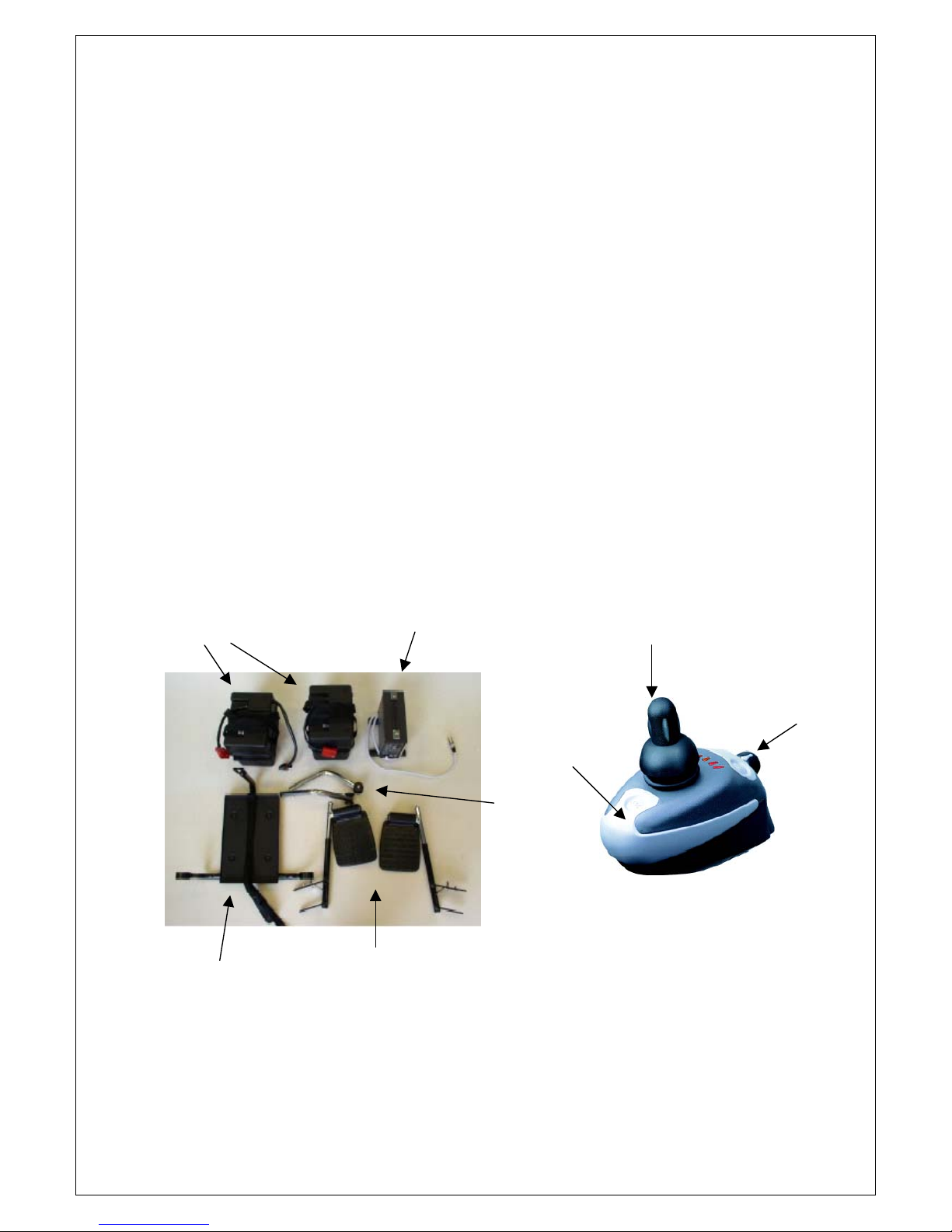
On receipt of your Power chair unpack the box and lay out, the following items will be
required Wheelchair frame complete with motors, gearboxes, armrests fitted and
upholstery.
One pair of leg rests
One battery tray
Two battery boxes complete with batteries or one battery box complete with batteries.
(Usually packed in a separate box)
One pair of anti tippers
One controller (Attached to chair)
Owner’s manual
Two battery boxes
3
Battery Charger
One pair of leg rests
Anti
tippers
Battery Tray
Shark Controller
Speed
Controller
J
oystick
If you require assistance in commissioning your Powerchair, ring Invacare New
Zealand on Free phone 0508 468 2227
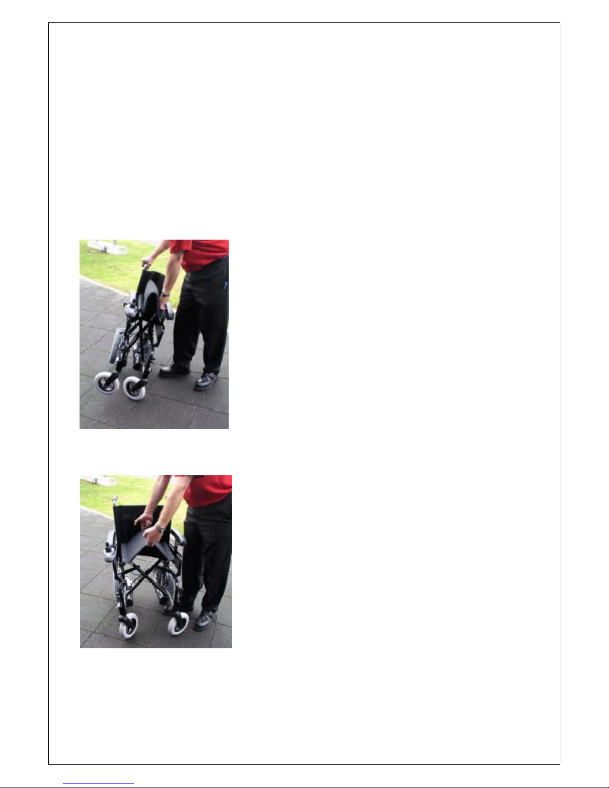
UNFOLDING YOUR POWERCHAIR
1. Move to one side of the Powerchair
2. Take hold of the push handle grip nearest you
3. Lean the chair slightly towards you and push down on the seat edge nearest to you.
4. As the set descends the chair will open, push down on both seat rails until they sit in
the U shaped saddles.
Please note that for folding the chair, the simplest method is to take hold of the front and
the back of the seat upholstery in the middle and lift. (Practise this now while you have the
opportunity)
This will cause the cross arms to rise and the chair to fold.
Unfolding the chair
4
Folding the chair
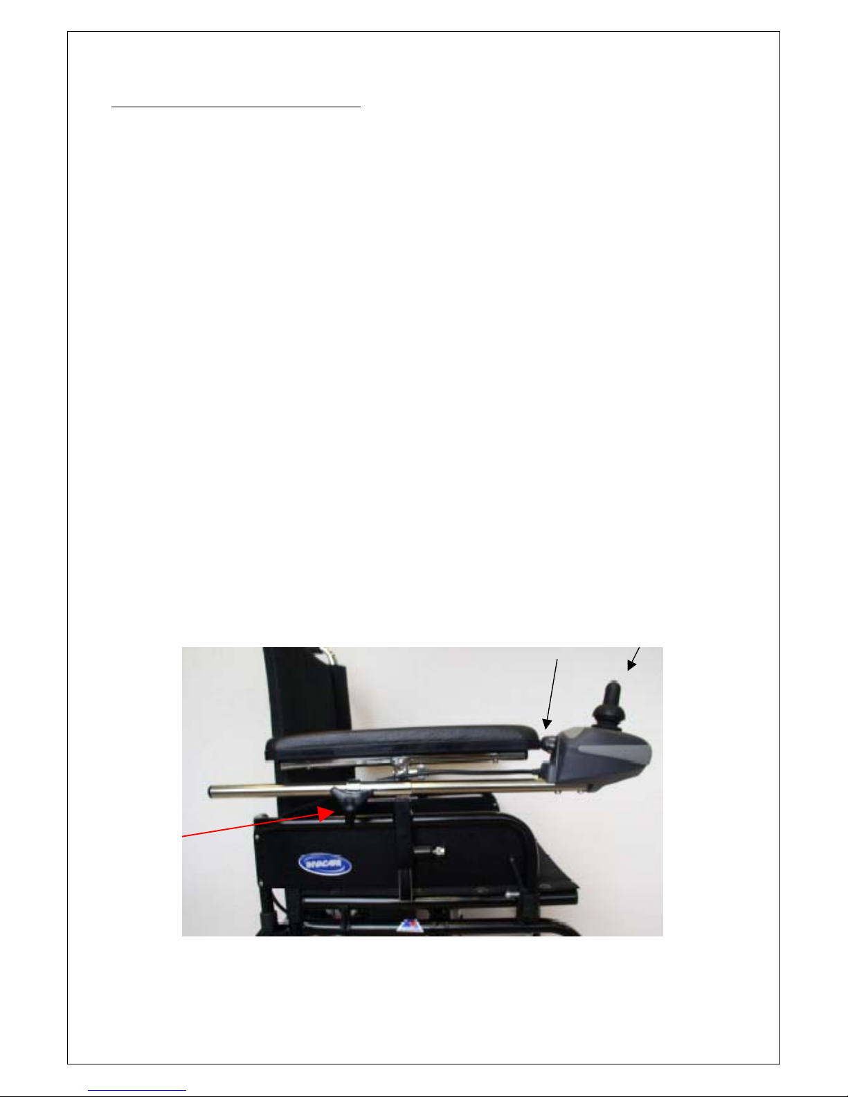
CONTROL SYSTEM
Fitting The Shark Control System
The Shark Controller should be mounted on the Powerchair using the bracketry supplied
and connected to the Powerchair electrical system.
The Shark Controller on your Powerchair determines which side you would like the
Controller located. (This should have been specified at the time your Powerchair was
ordered, but the machine is designed in such a way that it can be changed should this
prove necessary)
The sliding mounting arm should be secured to the underside of the controller, then the
arm should be located in its mounting bracket under the armrest pad, and secured in the
appropriate position with the screw fitting provided.
The Shark Controller is supplied with a battery charger indicator, all six lights indicate fully
charged batteries.
(See diagnostics section of this manual for further information).
Note 1: Changing the Controller from one side of the chair to the other involves the
relocation of the sliding mounting arm and relocation of the controller cable.
Note 2: The Shark Controller has a sleep mode, the controller will turn itself off after 10
minutes if not in use (this is to conserve battery power). To regain power simply depress
the power button or deflect the joystick.
5
Speed Controller Joystick
Controller Arm
Adjustment
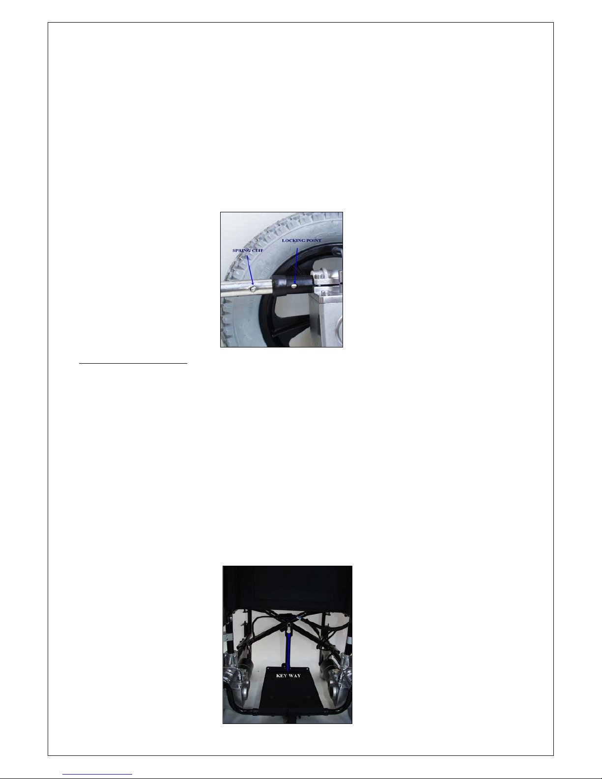
Fitting the Anti Tippers
1. With both anti tippers move to the rear of the chair.
2. Taking the non-wheel end, insert anti tipper into the chair frame directly behind the
motors.
3. Squeeze the spring clip domes protruding from the surface of the anti tip until they are
inside the frame.
4. Slide anti tipper into tube until the spring clip domes pop out of the holes on the frame,
repeat this on the other side.
5. To release anti tippers, squeeze spring clip domes and withdraw the anti tippers.
CAUTION: Anti tippers are to be used at all times, failure to use could cause serious
injury.
Fitting The Batteries
1. With Batteries in Battery Boxes and tray, move to the rear of the chair.
2. Place keyway shaped hole on the battery tray over the bolt on cross bracing under the
chair.
3. Rest rear tray hooks forward of the anti tipper bars. The tray should be latched into
position.
4. Place battery boxes with batteries enclosed on to battery tray black plug to the front,
battery box with the red and black plug first.
5. Connect battery box plugs together (red), strap into place.
6. Connect the black plug from the front of the battery box to the short loom (aprox.
150mm long with a plug at the either end) connect the other end to the Power Module.
The Power Module is either located on the left or right under the seat at the rear.
6
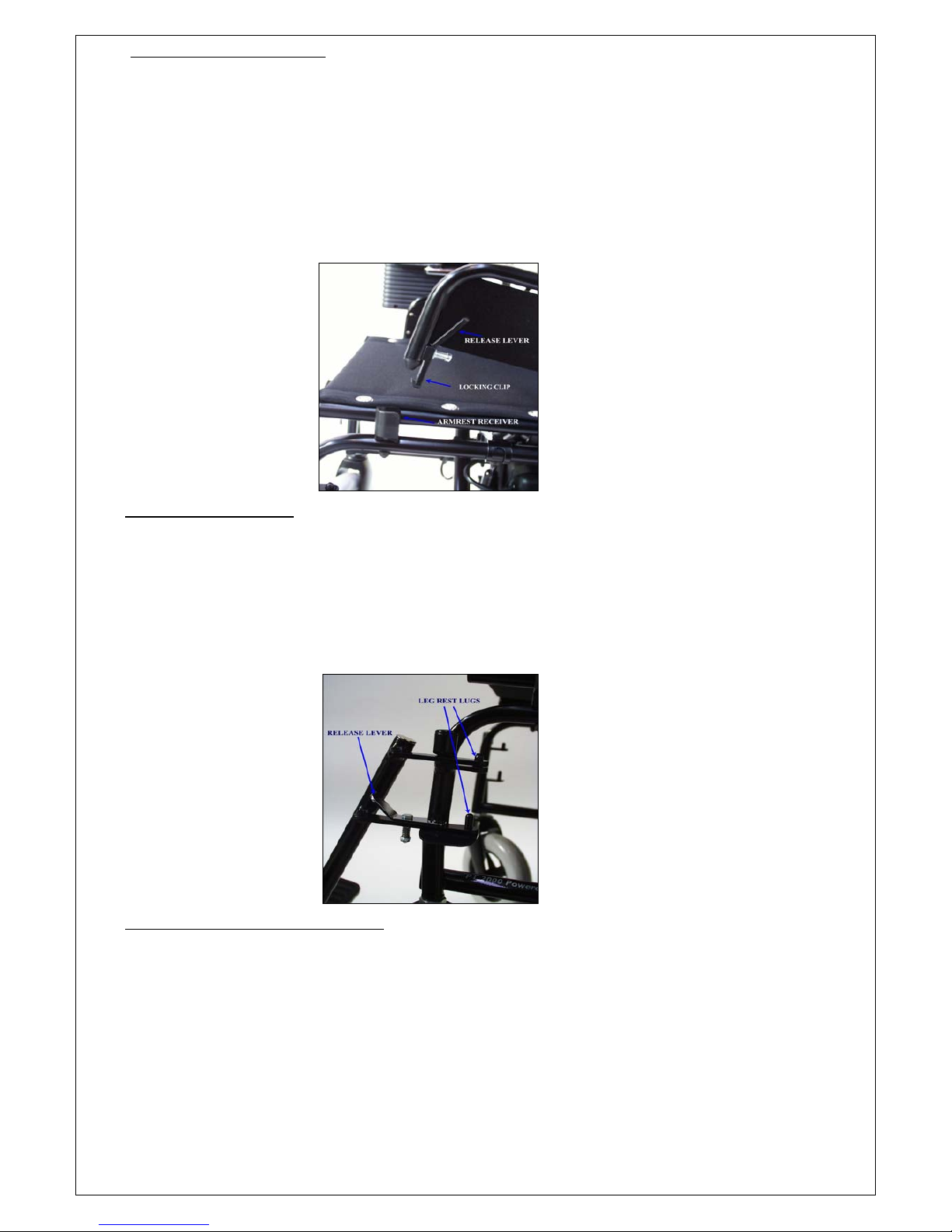
Setting Armrest Height
Your chair is supplied with swing back height adjust armrests, as standard.
1. To release the swing back arms, depress the clip on armrest frame found at the front of
the armrest at the base on the outside, once depressed the arm can be swung back and
out of position to aid transferring.
2. To adjust the height of the armrest pad, locate the finger toggle half way down the
armrest stem, turn anti clockwise then adjust height, lock in toggle. (Please note:
secure toggle with a pair of pliers for a tight fit).
Fitting The Legrests
The leg rests should be fitted from the side using the leg rest locating lugs, these are
located at the front on each side of the Powerchair.
The leg rests should then be able to be swung into a forward position where they will be
located by the spring loaded lever, this will lock them into place.
(Footplates pointing to
the inside of the chair).
Adjustment of Footrest Height
This is adjusted by loosening the bolt at the bottom of the footrest, tap upwards on the
head of the bolt to release the internal wedge, adjust to the correct height and retighten
the bolt.
7
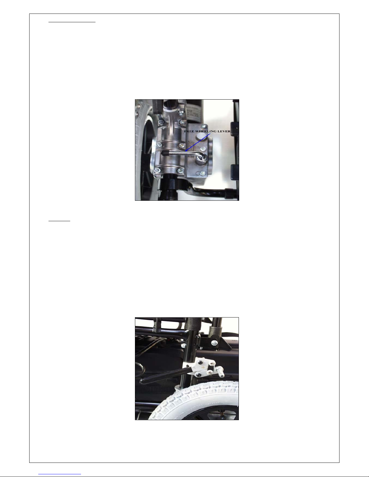
Gear Selection
Each power unit (left and right) incorporates a neutral and in gear position.
By turning both the levers on the Gear Boxes to the rearward position, it will disengage the
motor and gear box, this will place the power chair in a free wheeling mode.
Turn both the levers to the side, this will place both the motors into gear, and the chair is
now ready for driving.
CARE must be used AT ALL TIMES when the drive wheels are disengaged from the motors
and the manual parking brakes are NOT applied. Attendants pushing the wheelchair may
NOT be able to control the wheelchair on a steep sloping surface.
Gear Lever in Drive mode.
Brakes
The PT2000 is fitted with three braking systems:
1. Dynamic braking for slowing and stopping the wheelchair. This is automatic and
controlled by the movement of the joystick.
2. Solenoid controlled braking which, is an electric parking brake and is also automatic,
operating when the joystick is returned to neutral. You may hear a click when the
brakes engage/disengage.
3. Manual parking brakes for use when the drive wheels are disengaged from the motors.
4. Safety tip, if driving and you get into difficulty, just release the joystick and the brakes
will automatically come on, do not try to stop using any parts of your body.
8
Manual Brake in off position.

FOLDING AND TRANSPORTATION
The removal of each item follows this simple procedure:
Controller The controller can be left in place with the controller cable connected to the
power module.
Footrests Unless specifically requested, legrests are all swing-away and removable. Flip
up footplates and depress clip at the leg rest mounting point, swing leg rest
to the rear lift and remove.
Batteries Disconnect battery power lead from battery box (black plug). Disconnect the
two red battery plugs, release the battery box fixing strap, remove batteries
and tray.
Folding Chair
After completing the above steps, you are now ready to fold your Power chair. Move to one
side of the machine. Grasp the upholstery of the seat at the centre front and back, lean
chair slightly toward you and pull upwards. The chair will fold.
Note: Disengage the motor and gearbox (left and right) to enable the freewheel ability of
your chair, this will aid manoeuvrability.
Your Power chair is now ready for transportation folded.
CARE AND MAINTENANCE OF YOUR POWERCHAIR
(See page 28 for more detailed instructions)
To ensure smooth and reliable operation of all of the parts or your machine, it should be
kept as clean as possible under individual operators circumstances.
The upholstery on the chair may be wiped over with a damp cloth. Harsh abrasives are not
recommended.
The frame should be cleaned from time to time. Methylated spirits is ideal for this. A small
amount on a soft cloth is all that is needed.
The front castor wheels should be removed, cleaned and bearings checked on a 6 monthly
cycle due to the build up of fibre etc. A recommended service agent should carry this out.
Front castor forks should not be removed. These are held in with ”Lock Tight” (of a
removable grade). That must be re-applied, if the forks are removed, otherwise the Castor
will vibrate loose with use.
Where possible keep water away from the wheelchair, especially around the control box
and joystick. However carefully wipe off spilled drinks, salt water etc. with a clean damp
cloth, then wipe wheelchair dry with a soft dry cloth.
After maintenance, adjustments, or cleaning, always check for correct functioning of
brakes, steering and control before returning to use
Service or Repair
9
In the first instance contact your supplier/funder of your Powerchair if repair and servicing
is required.
 Loading...