

Invacare ProntoTM M6, Pronto M6 Owner's Manual
Owner's Operator And Maintenance Manual
ProntoTM M6
DEALER: THIS MANUAL MUST BE GIVEN TO THE USER OF
THE WHEELCHAIR.
USER: BEFORE USING THIS WHEELCHAIR, READ THIS
MANUAL AND SAVE FOR FUTURE REFERENCE.

2
W
A
R
N
I
N
G
WARNING
W ARNING
DO NOT OPERATE THIS EQUIPMENT WITHOUT FIRST READING
AND UNDERST ANDING THIS MANUAL. IF YOU ARE UNABLE TO
UNDERST AND THE WARNINGS, CAUTIONS, AND INSTRUCTIONS,
CONTACT A HEAL THCARE PROFESSIONAL, DEALER OR TECHNI-
CAL PERSONNEL IF APPLICABLE BEFORE ATTEMPTING TO USE THIS
EQUIPMENT - OTHERWISE INJURY OR DAMAGE MAY RESUL T.
THE INITIAL SET UP OF THIS WHEELCHAIR MUST BE PERFORMED
BY A QUALIFIED TECHNICIAN.
PROCEDURES OTHER THAN THOSE DESCRIBED IN THIS
MANUAL
MUST BE PERFORMED BY A QUALIFIED TECHNICIAN.
SPECIAL NOTES
WARNING/CAUTION notices as used in this manual apply to hazards or unsafe practices
which could result in personal injury or property damage.
NOTICE
INFORMA TION CONTAINED IN THIS DOCUMENT IS SUBJECT TO CHANGE WITHOUT NOTICE.
WHEELCHAIR USER
As a manufacturer of wheelchairs, Invacare endeavors to supply a wide variety of wheelchairs to meet many needs of the user. However, final selection of the type of wheelchair
to be used by an individual rests solely with the user and his/her healthcare professional
capable of making such a selection.
WHEELCHAIR TIE-DOWN RESTRAINTS AND SEA T POSITIONING STRAPS
Invacare recommends that wheelchair users NOT be transported in vehicles of any kind
while in wheelchairs. As of this date, the Department of Transportation has not approved
any tie-down systems for transportation of a user while in a wheelchair, in a moving vehicle
of any type.
It is Invacare’s position that users of wheelchairs should be transferred into appropriate
seating in vehicles for transportation and use be made of the restraints made available by
the auto industry. Invacare cannot and does not recommend any wheelchair transportation systems.
AS REGARDS RESTRAINTS - SEAT POSITIONING STRAPS - IT IS THE OBLIGATION OF THE DME
DEALER, THERAPISTS AND OTHER HEALTHCARE PROFESSIONALS TO DETERMINE IF A SEAT POSITIONING STRAP IS REQUIRED TO ENSURE THE SAFE OPERATION OF THIS EQUIPMENT BY THE
USER. SERIOUS INJURY CAN OCCUR IN THE EVENT OF A FALL FROM A WHEELCHAIR.
SA VE THESE INSTRUCTIONS

3
T ABLE OF CONTENTS
T
A
B
L
E
O
F
C
O
N
T
E
N
T
S
TABLE OF CONTENTS
SPECIAL NOTES ..................................... 2
SPECIFICA TIONS ..................................... 4
PROCEDURE 1 - GENERAL GUIDELINES .. 5
CONTROLLER SETTINGS.......................... 5
REPAIR OR SERVICE INFORMATION ......... 5
OPERATING INFORMATION ....................... 5
SAFETY/HANDLING OF WHEELCHAIRS .... 8
WARNING/CAUTION LABEL LOCATION .... 11
PROCEDURE 2 - SAFETY INSPECTION
CHECKLIST/TROUBLESHOOTING ........ 12
SAFETY INSPECTION CHECKLIST ........... 12
TROUBLESHOOTING GUIDE ..................... 13
PROCEDURE 3 - WHEELCHAIR
OPERA TION........................................... 14
WHEELCHAIR OPERATION ...................... 14
PROCEDURE 4 - ARMS .......................... 16
ARMREST ANGLE ADJUSTMENT ............. 16
ARMREST WIDTH ADJUSTMENT ............. 16
ARMREST DEPTH ADJUSTMENT ............. 17
ARMREST HEIGHT ADJUSTMENT ............ 17
PROCEDURE 5 - SEA T........................... 18
REMOVING/INSTALLING SEAT SUPPORT
COLLARS ............................................... 18
REMOVING/INSTALLING THE SEAT
ASSEMBLY ............................................. 19
ADJUSTING THE SEAT HEIGHT ................ 21
ADJUSTING THE SEAT SUPPORT
POSTS.................................................... 23
ADJUSTING THE SEAT DEPTH ................. 24
REPLACING THE SEAT POSITIONING
STRAP .................................................... 25
PROCEDURE 6 - BACK.......................... 26
FOLDING/UNFOLDING THE BACK .......... 26
ADJUSTING THE BACK ANGLE ................ 26
ADJUSTING THE HEADREST .................... 26
PROCEDURE 7 - FOOTBOARD
ASSEMBL Y....................................... 27
REMOVING/INSTALLING/ADJUSTING THE
FOOTBOARD ASSEMBLY ....................... 27
ADJUSTING THE FOOTBOARD
ASSEMBLY ANGLE ................................. 28
PROCEDURE 8 - SHROUD/WHEELS...... 29
REPLACING THE FOAM FILLED TIRES
ONTO THE WHEEL RIM .........................
29
REMOVING/INSTALLING THE SHROUD ....29
ENGAGING/DISENGAGING MOTOR
LOCKS...................................................
29
REMOVING/INSTALLING THE AXLE
SHROUD COVERS ................................
31
REPLACING THE FRONT/REAR
CASTER ASSEMBLIES ..........................
31
PROCEDURE 9 - BA TTERIES................. 32
REMOVING/INSTALLING BATTERIES
WITHOUT REMOVING CABLES .............. 32
CONNECTING/DISCONNECTING
BATTERY CABLES.................................. 33
CONNECTING/DISCONNECTING
CIRCUIT BREAKER CABLES ..................34
REPLACING BATTERIES ........................... 35
WHEN TO CHARGE BATTERIES............... 36
CHARGING BATTERIES ............................ 36
BATTERY CHARGER OPERATION ............38
PROCEDURE 10 - ELECTRONICS .......... 40
RETRACTING THE MKIV JOYSTICK ......... 40
REPOSITIONING THE MKIV JOYSTICK .... 41
DISCONNECTING/CONNECTING THE
MKIV JOYSTICK .....................................
41
PROCEDURE 11 - TRANSPORT............. 42
TRANSPORTING THE WHEELCHAIR ....... 42
PROCEDURE 12 - OPTIONS .................. 44
REMOVING/INSTALLING THE CRUTCH
CANE HOLDER ....................................... 44
REMOVING/INSTALLING THE SAFETY
FLAG ......................................................44
NOTES .................................................. 45
WARRANTY........................................... 47

4
SPECIFICATIONS
PRONTO™ M6
Seat Width Range: 17 - inches
Seat Depth: 17 1/2 - inches-with headrest
Back Height Range: 21 - inches to 27 - inches - In 1 - inch increments
Back Angle Range: 80
o
to 115
o
Seat-to-Floor: 19 1/4 to 20 3/4 - inches
Overall Width
(No joystick): 23 - inches
Overall Height: 39 3/4 to 47 1/4 - inches
Overall Length 31 1/2 to 33 1/2 - inches (With Footboard Folded)
42 to 44 - inches (With Footboard Down)
Drive Wheels/Tires 10 x 3 1/2 - inch (Flat Free-Standard)
Caster w/Precision
Sealed Bearings: 6.0 x 1.3 - inch Front
5.0 x 1.2 - inch Rear
Footrests/Legrests: Flip Up, Depth Adjustable
Weight
1
W/O Batteries: 153 lbs.
W/Batteries (Gel Cell): 205 lbs.
Shipping: 253 lbs.
Armrests: Adjustable Width, Angle, Height and Depth
Upholstery: Gray Cloth
Batteries: U1 Gel Cell - Quantity 2
PERFORMANCE
Speed (M.P.H.): 0 to 4 1/2
Turning Radius: 24-inches
Range (variable)2: 14 miles
L W eight Limitation: 250 lbs.
L
NOTE: Refer to PERCENTAGE OF WEIGHT DISTRIBUTION in PROCEDURE 1 of this manual.
Footnotes:
1. Includes seating systems and accessories.
2. Range will vary with battery conditions, surface, terrain and operators weight.
SPECIFICATIONS
S
P
E
C
I
F
I
C
A
T
I
O
N
S

5
This Procedure Includes the Following:
Controller Settings
Repair or Service Information
Operating Information
Safety/Handling of Wheelchairs
Warning/Caution Label Location
WARNING
REPAIR OR SERVICE/CONTROLLER SETTINGS
Set-up of the Electronic Control Unit is to be performed ONL Y by a qualified technician. The final
tuning adjustments of the controller may affect other activities of the wheelchair. Reprogramming the controller reduces the stability/controllability of the wheelchair. Other program settings could cause the wheelchair to tip over resulting in serious injury to the user and/or damage to the surrounding property. If any individual other than a qualified technician performs
any work on these units, the warranty is void.
OPERA TING INFORMATION
GENERAL WARNINGS
Performance adjustments should only be made by professionals of the healthcare field or
persons fully conversant with this process and the driver's capabilities. Incorrect settings could
cause injury to the driver, bystanders, damage to the chair and to surrounding property.
After the wheelchair has been set-up, check to make sure that the wheelchair performs to the
specifications entered during the set-up procedure. If the wheelchair does NOT perform to
specifications, turn the wheelchair OFF immediately and reenter set-up specifications. Repeat
this procedure until the wheelchair performs to specifications.
AL WAYS shift your weight in the direction you are turning. DO NOT shift your weight in the opposite direction of the turn. Shifting your weight in the opposite direction of the turn may cause the
inside drive wheel to lose traction and the wheelchair to tip over.
DO NOT shift your weight or sitting position toward the direction you are reaching as the wheelchair may tip over.
DO NOT engage or disengage the motor locks until the power is in the OFF position.
DO NOT operate on roads, streets or highways.
DO NOT climb, go up or down ramps or traverse slopes greater than 9
o
.
DO NOT attempt to move up or down an incline with a water, ice or oil film.
DO NOT attempt to drive over curbs or obstacles. Doing so may cause your wheelchair to turn
over and cause bodily harm or damage to the chair.
DO NOT use parts, accessories, or adapters other than those authorized by Invacare.
DO NOT leave the power button ON when entering or exiting your wheelchair.
DO NOT stand on the frame of the wheelchair.
DO NOT stand on the flip-up footboard. When getting in or out of the wheelchair, make sure
that the flip-up footboard is in the upward position .
AL WAYS wear your seat positioning strap.
G
E
N
E
R
A
L
G
U
I
D
E
L
I
N
E
S
GENERAL GUIDELINES PROCEDURE 1

6
GENERAL GUIDELINESPROCEDURE 1
GENERAL W ARNINGS (CONTINUED)
ACCESSORIES
EXTREME care should be exercised when using oxygen in close proximity to electric circuits.
Contact your oxygen supplier for instruction in the use of oxygen.
BA TTERIES
The warranty and performance specifications contained in this manual are based on the use
of deep cycle gel cell or sealed lead acid batteries. Invacare strongly recommends their use
as the power source for this unit.
Carefully read battery/battery charger information prior to installing, servicing or operating your
wheelchair.
CHARGING BA TTERIES
Carefully read all warnings, cautions and any other information printed on the battery charger
prior to recharging the batteries.
NEVER attempt to recharge the batteries by attaching cables directly to the battery terminals.
DO NOT attempt to recharge the batteries and operate the wheelchair at the same time.
DO NOT attempt to recharge the batteries when the wheelchair has been exposed to
ANY type of moisture.
DO NOT attempt to recharge the batteries when the wheelchair is outside.
DO NOT sit in the wheelchair while recharging the batteries.
DO NOT attempt to recharge the batteries using BOTH the on-board battery charger AND an
independent battery charger (plugged into the joystick charger port) at the SAME time. Doing
so will reduce the life of the batteries.
GROUNDING INSTRUCTIONS:
DO NOT, under any circumstances, cut or remove the round grounding prong from any plug
used with or for Invacare products. Some devices are equipped with three-pr ong (grounding)
plugs for protection against possible shock hazards and fire. Where a two-prong wall receptacle is encountered, it is the personal responsibility and obligation of the customer to contact
a qualified electrician and have the two-prong receptacle replaced with a properly gr ounded
three-prong wall receptacle in accordance with the National Electrical Code. If you must use
an extension cord, use ONL Y a three-wire extension cor d having the same or higher electrical
rating as the device being connected. In addition, Invacare has placed RED/ORANGE W ARNING T AGS on some equipment. DO NOT r emove these tags.
RAIN TEST
INVACARE has tested it’s power wheelchairs in accordance with ISO 7176 Part 9 “Rain Test”. This
provides the end user or his/her assistant sufficient time to remove his/her power wheelchair from
a rain storm and retain wheelchair operation.
DO NOT leave power wheelchair in a rain storm of any kind.
DO NOT use power wheelchair in a shower or leave it in a damp bathroom while taking a shower.
DO NOT leave power wheelchair in a damp area for any length of time.
Direct exposure to rain or dampness will cause the chair to malfunction electrically and me-
chanically; may cause the chair to prematurely rust or may damage the upholstery.
Check to ensure that the red and black battery terminal caps are secured in place, joystick boot is
NOT torn or cracked where water can enter and that all electrical connections are secure at all times.
DO NOT use the joystick if the boot is torn or cracked. If the joystick boot becomes torn or
cracked, replace IMMEDIA TELY.
G
E
N
E
R
A
L
G
U
I
D
E
L
I
N
E
S

7
G
E
N
E
R
A
L
G
U
I
D
E
L
I
N
E
S
GENERAL GUIDELINES PROCEDURE 1
GENERAL WARNINGS (CONTINUED)
WEIGHT TRAINING
Invacare DOES NOT recommend the use of its wheelchairs as a weight training apparatus. Invac-
are wheelchairs have NOT been designed or tested as a seat for any kind of weight training. If
occupant uses said wheelchair as a weight training apparatus, INVACARE SHALL NOT BE LIABLE
FOR BODILY INJURY AND THE W ARRANTY IS VOID.
WEIGHT LIMIT ATION
The Pronto™ M6 model has a weight limitation of 250 lbs.
WARNING
CAUTION: IT IS VERY IMPORT ANT THA T YOU READ THIS INFORMATION REGARDING THE POSSIBLE EFFECTS OF ELECTROMAGNETIC INTERFERENCE ON YOUR POWERED WHEELCHAIR.
ELECTROMAGNETIC INTERFERENCE (EMI) FROM RADIO WAVE SOURCES
Powered wheelchairs and motorized scooters (in this text, both will be referred to as pow-
ered wheelchairs) may be susceptible to electromagnetic interference (EMI), which is
interfering electromagnetic energy (EM) emitted from sources such as radio stations, TV
stations, amateur radio (HAM) transmitters, two way radios, and cellular phones. The interference (from radio wave sources) can cause the powered wheelchair to r elease its brakes,
move by itself, or move in unintended directions. It can also permanently damage the
powered wheelchair's control system. The intensity of the interfering EM energy can be
measured in volts per meter (V/m). Each powered wheelchair can resist EMI up to a
certain intensity. This is called its "immunity level." The higher the immunity level, the greater
the protection. At this time, current technology is capable of achieving at least a 20 V/m
immunity level, which would provide useful protection from the more common sour ces of
radiated EMI. This powered wheelchair model as shipped, with the INT/DL40i Non-Programmable (NP) electronics, has an immunity level of unknown.
There are a number of sources of relatively intense electr omagnetic fields in the everyday
environment. Some of these sources are obvious and easy to avoid. Others ar e not apparent and exposure is unavoidable. However, we believe that by following the warnings
listed, your risk to EMI will be minimized.
The sources of radiated EMI can be broadly classified into three types:
1) Hand-held Portable transceivers (transmitters-receivers with the antenna mounted
directly on the transmitting unit. Examples include: citizens band (CB) radios, "walkie
talkie," security, fire, And police transceivers, cellular telephones, and other personal
communication devices. **NOTE: Some cellular telephones and similar devices transmit signals while they are ON, even when not being used;
2) Medium-range mobile transceivers, such as those used in police cars, fire trucks, ambulances, and taxis. These usually have the antenna mounted on the outside of the
vehicle; and
3) Long-range transmitters and transceivers, such as commercial broadcast transmitters (radio and TV broadcast antenna towers) and amateur (HAM) radios.
NOTE: Other types of hand-held devices, such as cordless phones, laptop computers,
AM/FM radios, TV sets, CD players, cassette players, and small appliances, such as electric
shavers and hair dryers, so far as we know, are not likely to cause EMI problems to your
powered wheelchair.

8
GENERAL GUIDELINESPROCEDURE 1
G
E
N
E
R
A
L
G
U
I
D
E
L
I
N
E
S
SAFETY/HANDLING OF
WHEELCHAIRS
“Safety and Handling” of the wheelchair requires the
close attention of the wheelchair user as well as the
assistant. This manual points out the most common
procedures and techniques involved in the safe operation and maintenance of the wheelchair. It is important to practice and master these safe techniques
until you are comfortable in maneuvering around the
frequently encountered architectural barriers.
Use this information only as a “basic” guide. The techniques that are discussed on the following pages have
been used successfully by many.
Individual wheelchair users often develop skills to
deal with daily living activities that may differ from
those described in this manual. Invacare recognizes
and encourages each individual to try what works
best for him/her in overcoming architectural obstacles
WARNINGS
POWERED WHEELCHAIR ELECTROMAGNETIC INTERFERENCE (EMI)
Because EM energy rapidly becomes more intense as one moves closer to the transmitting
antenna (source), the EM fields from hand-held radio wave sour ces (transceivers) are of special concern. It is possible to unintentionally bring high levels of EM energy very close to the
powered wheelchair's control system while using these devices. This can affect powered wheelchair movement and braking. Therefore, the warnings listed are recommended to prevent
possible interference with the control system of the powered wheelchair.
Electromagnetic interference (EMI) from sources such as radio and TV stations, amateur
radio (HAM) transmitters, two-way radios, and cellular phones can affect powered wheelchairs and motorized scooters. Following the warnings listed below should reduce the
chance of unintended brake release or powered wheelchair movement which could
result in serious injury.
1) Do not operate hand-held transceivers (transmitters receivers), such as citizens band
(CB) radios, or turn ON personal communication devices, such as cellular phones,
while the powered wheelchair is turned ON;
2) Be aware of nearby transmitters, such as radio or TV stations, and try to avoid coming
close to them;
3) If unintended movement or brake release occurs, turn the powered wheelchair OFF
as soon as it is safe;
4) Be aware that adding accessories or components, or modifying the powered wheelchair, may make it more susceptible to EMI (Note: There is no easy way to evaluate
their effect on the overall immunity of the powered wheelchair); and
5) Report all incidents of unintended movement or brake release to the powered wheelchair manufacturer, and note whether there is a source of EMI nearby.
IMPORTANT INFORMATION
1) 20 volts per meter (V/m) is a generally achievable and useful immunity level against
EMI (as of May 1994) (the higher the level, the greater the protection);
2) The immunity level of this product is unknown.
that they may encounter, however, ALL WARNINGS
and CAUTIONS given in this manual MUST be followed. Techniques in this manual are a starting point
for the new wheelchair user and assistant with “safety”
as the most important consideration for all.
Stability and Balance
WARNING
AL WAYS wear your seat positioning strap.
To assure stability and proper operation of your wheelchair, you must at all times maintain proper balance.
Your wheelchair has been designed to remain upright and stable during normal daily activities as long
as you do not move beyond the center of gravity.
DO NOT lean forward out of the wheelchair any further than the length of the armrests.
9
Transferring to and From Other Seats
WARNING
ALWAYS turn the wheelchair power OFF and
engage the motor locks to prevent the
wheels from moving BEFORE attempting to
transfer in or out of the wheelchair. Also, make
sure every precaution is taken to reduce the
gap distance by aligning both the front AND
rear casters parallel with the object you are
transferring onto.
CAUTION
When transferring, position yourself as far back
as possible in the seat. This will prevent broken screws, damaged upholstery and the
possibility of the wheelchair tipping forward.
NOTE: This activity may be performed independently
provided you have adequate mobility and upper body
strength.
1. Position the wheelchair as close as possible
along side the seat to which you are transferring, with the rear casters pointing away from it.
G
E
N
E
R
A
L
G
U
I
D
E
L
I
N
E
S
GENERAL GUIDELINES PROCEDURE 1
7. Repeat STEPS 4-6 for the rear frame assembly.
ESCALATORS? SORRY!
DO NOT use an escalator to move a wheelchair
between floors. Serious bodily injury may occur.
Coping With Everyday Obstacles
Coping with the irritation of everyday obstacles can
be alleviated somewhat by learning how to manage
your wheelchair. Keep in mind your center of gravity
to maintain stability and balance.
A Note to Wheelchair Assistants
When assistance to the wheelchair user is required,
remember to use good body mechanics. Keep your
back straight and bend your knees whenever tilting
wheelchair or traversing curbs, or other impediments.
Also, be aware of detachable parts such as arms or
the footboard. These must NEVER be used for handhold or lifting supports, as they may be inadvertently
released, resulting in possible injury to the user and/
or assistant(s).
When learning a new assistance technique, have
an experienced assistant help you before attempting it alone.
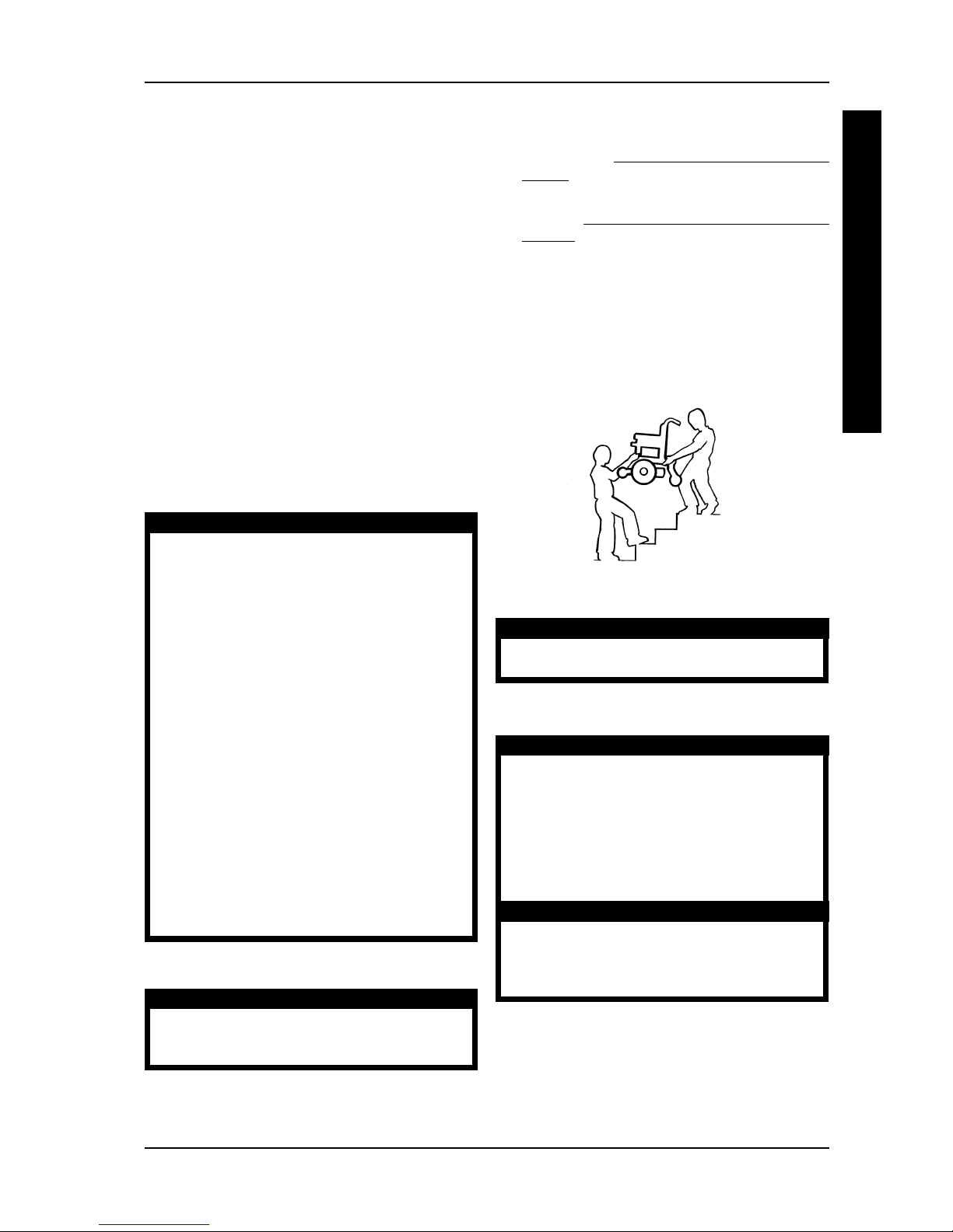
Stairways
WARNING
DO NOT attempt to move an occupied
power wheelchair between floors using a
stairway. Use an elevator to move an occupied power wheelchair between floors. If
moving a power wheelchair between floors
by means of a stairway, the occupant MUST
be removed and transported independently
of the power wheelchair.
Extreme caution is advised when it is necessary
to move an UNOCCUPIED power wheelchair
up or down the stairs. Invacare recommends
using two (2) assistants and making thorough
preparations. Separate the front frame assembly of the wheelchair from the rear frame
assembly of the wheelchair. Make sure to use
ONL Y secure, non-detachable parts for handhold supports.
DO NOT attempt to lift the wheelchair by any
removable (detachable) parts. Lifting by
means of any removable (detachable) parts
of a wheelchair may result in injury to the user
or damage to the wheelchair.
Follow this procedure for moving the wheelchair
between floors when an elevator is NOT available:
WARNING
The weight of the wheelchair without the user
and batteries is 153 lbs. Use proper lifting techniques (lift with your legs) to avoid injury.
1. Remove the occupant from the wheelchair.
2. Separate the front frame assembly of the wheelchair from the rear frame assembly of the wheelchair. Refer to TRANSPORTING THE WHEELCHAIR in PROCEDURE 10 of the manual.
3. Remove the battery boxes from the wheelchair.
Refer to
INSTALLING/REMOVING THE BAT-
TERIES in PROCEDURE 9 of this manual.
4. Bend your knees and keep your back straight.
5. Using non-removable (non-detachable) parts of
the wheelchair, lift the front frame assembly off
of the ground and transfer it up or down the stairs.
6. The front frame assembly should not be lowered until the last stair has been negotiated and
the front frame assembly has been carried away
from the stairway.
10
GENERAL GUIDELINESPROCEDURE 1
G
E
N
E
R
A
L
G
U
I
D
E
L
I
N
E
S
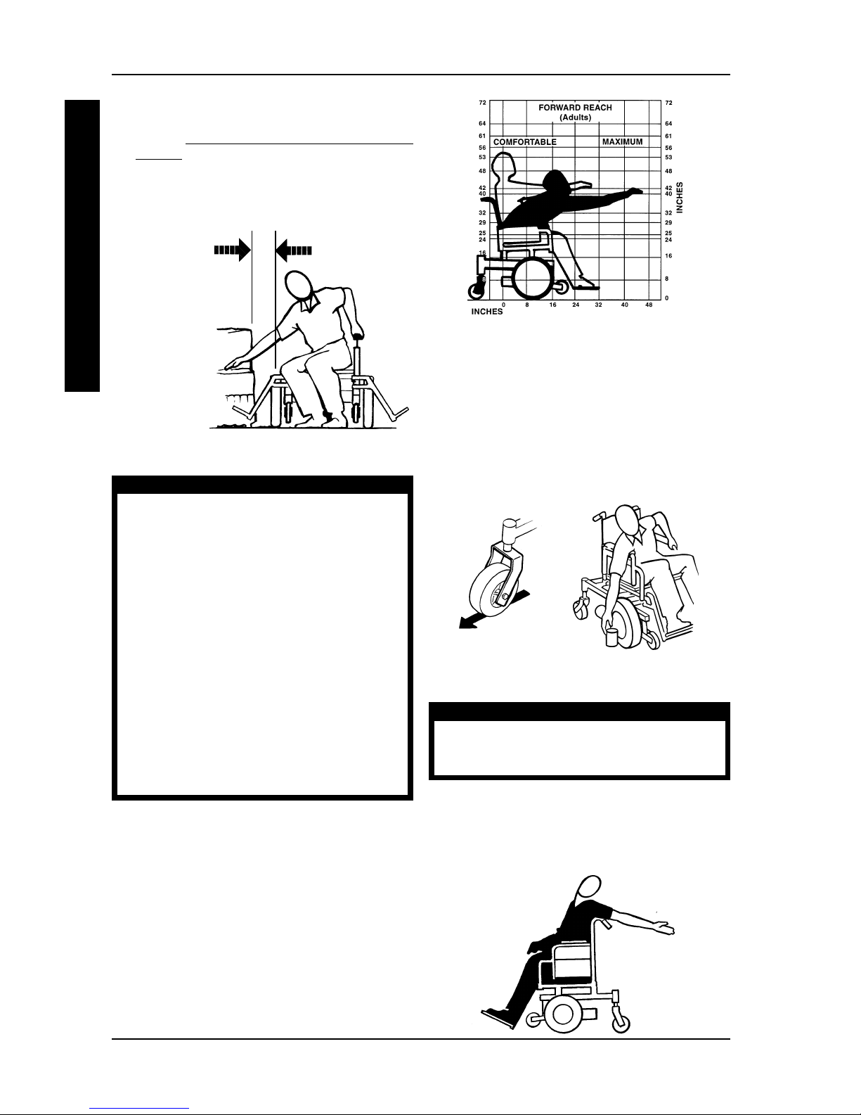
Reaching, Bending - Backward
WARNING
DO NOT lean over the top of the back upholstery. This will change your center of
gravity and may cause you to tip over.
Position wheelchair as close as possible to the desired object. Point the front AND rear casters rearward to create the longest possible wheelbase.
Reach back only as far as your arm will extend without changing your sitting position.
Reaching, Leaning, Bending and Bending Forward
Position the front AND rear casters so that they
are extended as far rearward as possible and engage motor locks. DO NOT ATTEMPT TO
REACH OBJECTS IF YOU HAVE TO MOVE
FORWARD IN THE SEAT OR PICK THEM UP
FROM THE FLOOR BY REACHING DOWN BETWEEN YOUR KNEES.
Percentage of Weight Distribution
W ARNING
DO NOT attempt to reach objects if you have
to move forward in the seat or pick them up
from the floor by reaching down between your
knees.
Many activities require the wheelchair user to
reach, bend and transfer in and out of the
wheelchair. These movements will cause a
change to normal balance, center of gravity,
and weight distribution of the wheelchair. To
determine and establish your particular safety
limits, practice bending, reaching and transferring activities in several combinations in the presence of a qualified healthcare professional BEFORE attempting active use of the wheelchair.
Proper positioning is essential for your safety.
When reaching, leaning, bending or bending
forward, it is important to use the casters as a
tool to maintain stability and balance.
Functional Reach From a Wheelchair
The approximate reach-limit values shown in the accompanying graphs were derived on the basis of a
sample of 91 male and 36 female wheelchair users.
Note the difference between the maximum and the
comfortable reach limits, a subjective but important consideration in design.
MINIMIZE GAP
DIST ANCE
2. After the wheelchair is positioned properly for
transfer, verify that the motor locks are engaged.
Refer to
ENGAGING/DISENGAGING MOTOR
LOCKS in PROCEDURE 7 of this manual.
3. Shift body weight into seat with transfer.
During independent transfer, little or no seat platform will
be beneath you. Use a transfer board if at all possible.
11
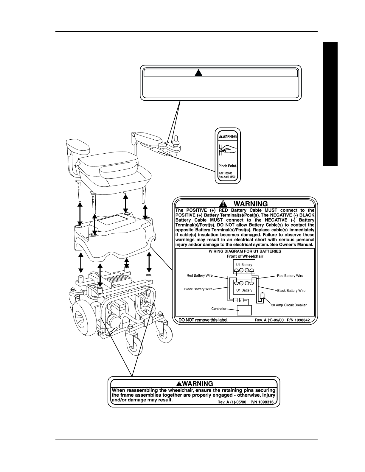
WARNING/CAUTION LABEL LOCATION - PRONTO™ M6
G
E
N
E
R
A
L
G
U
I
D
E
L
I
N
E
S
GENERAL GUIDELINES PROCEDURE 1
! WARNING
Positioning joystick PARALLEL to armrest allows wheelchair to be SLOWLY
maneuvered up to a desk/table. ANY other wheelchair operation is to be
performed with joystick secured with retaining pin in FRONTAL position otherwise injury or damage may result.
Rev. A (1)-05/00 P/N 1098340
NOTE: Warning label 1098342 is located UNDER
the shroud.

12
SAFETY INSPECTION CHECKLIST
This Procedure Includes the Following:
Safety Inspection Checklist
Troubleshooting Guide
Initial adjustments should be made to suit personal body structure and preference. Thereafter, follow these maintenance procedures:
ITEM
GENERAL (MECHANICAL TROUBLESHOOTING)
l Wheelchair rolls straight (no excessive drag
or pull to one side).
ARMS - (PROCEDURE 3)
l Secure but easy to release; adjustment
levers engage properly.
l Adjustable height arms operate and lock securely.
l Pivot points free of wear and looseness.
SEA T AND BACK UPHOLSTERY
l Inspect for rips or sagging.
SEA T
l Seat secured to the wheelchair frame.
l Remove seat release pins and inspect.
Replace if any signs of wear.
DRIVE WHEELS
lMounting bolts are secure.
lNo excessive side movement or binding when
lifted and spun when disengaged (free-wheeling).
CASTER ASSEMBLIES - (PROCEDURE 7)
l Bolts are tight.
lInspect caster assembly for proper tension
by spinning caster assembly; caster
assembly should come to a gradual stop.
CAUTION: As with any vehicle, the wheels and
tires should be checked periodically for cracks
and wear, and should be replaced.
CASTER ASSEMBLIES/WHEEL - (PROCEDURE 7)
l Ensure all fasteners are secure.
WHEELS/TIRES - (PROCEDURE 7)
l Inspect for flat spots and wear.
CAUTION: As with any vehicle, the wheels and
tires should be checked periodically for cracks
and wear, and should be replaced.
CLEANING
l Clean upholstery and armrests.
INSPECT/ INSPECT/ INSPECT/
ADJUST ADJUST ADJUST
INITIALLY WEEKL Y MONTHL Y PERIODICALLY
XX
XX
XX
XX
XX
XX
XX
X
X
XX
XX
XX
XX
XX
SAFETY INSPECTION/TROUBLESHOOTINGPROCEDURE 2
S
A
F
E
T
Y
I
N
S
P
E
C
T
I
O
N
T
R
O
U
B
L
E
S
H
O
O
T
I
N
G
NOTE: Every six (6) months take your wheelchair to a qualified dealer for a thorough inspection and
servicing. Regular cleaning will reveal loose or worn parts and enhance the smooth operation of your
wheelchair. To operate properly and safely, your wheelchair must be cared for just like any other
vehicle. Routine maintenance will extend the life and efficiency of your wheelchair.

13
SYMPTOM
LIMITED DRIVING DIST ANCE.
BATTERIES NOT CHARGING.
BA TTERIES DRAW
EXCESSIVE CURRENT
WHEN CHARGING.
CHARGE INDICA TOR
SHOWS LOW CHARGE
LEVEL IMMEDIA TELY AFTER
CHARGING.
BA TTERY INDICAT OR
FLASHES THE CHARGE
LEVEL IS LOW - TOO SOON
AFTER BEING RECHARGED.
WHEELCHAIR WILL NOT
DRIVE.
MOTOR “CHA TTERS” OR
RUNS IRREGULARL Y .
JOYSTICK ERRA TIC OR
DOES NOT RESPOND AS
DESIRED.
ONL Y ONE (1) REAR WHEEL
TURNS.
WHEELCHAIR DOES NOT
RESPOND TO COMMANDS.
POWER INDICA TOR OFF EVEN AFTER RECHARGING.
PROBABLE CAUSE
Batteries not charged long enough.
Batteries weak, won't hold charge.
Charger not working.
Battery Connections loose.
NO current at wall outlet.
BAD connection on Charger,
Charger Cable, Plug or Internal
Wiring problem.
Battery Failure.
Batteries weak, won't hold charge.
Electrical Malfunction
Charger not operating.
Have charger checked.
Weak batteries.
Motor locks disengaged.
Batteries require charging.
Charger plugged in.
Circuit breaker tripped.
Electrical malfunction.
Electrical malfunction.
Controller programmed improperly.
Electrical Malfunction.
One (1) motor lock is engaged.
Poor battery terminal connection.
Electrical malfunction.
SOLUTION
Charge batteries overnight or
ensure 8 hours of charge between
use times (PROCEDURE 8).
Replace Batteries
(PROCEDURE 8).
Switch on back of charger NOT
set to 115 volts (PROCEDURE 8).
Replace Charger.
Check all connections. Secure
connections (PROCEDURE 8).
Switch to another wall outlet.
Replace Charger or internal
repairs required. Contact Dealer
or Invacare.
Replace Batteries
(PROCEDURE 8).
Replace Batteries
(PROCEDURE 8).
Contact Dealer or Invacare.
Replace Charger.
Service or replace charger.
Contact Dealer or Invacare.
Replace batteries
(PROCEDURE 8).
Engage motor locks.
(PROCEDURE 7)
Charge batteries (PROCEDURE
8).
Unplug charger from scooter.
Reset breaker. If breaker trips
again, it may indicate need for internal repairs. Contact Dealer or
Invacare.
Contact Dealer or Invacare.
Contact Dealer or Invacare.
Contact Dealer or Invacare.
Contact Dealer or Invacare.
Disengage motor lock.
Clean terminals
(PROCEDURE 8).
Contact dealer or Invacare.
TROUBLESHOOTING GUIDE
S
A
F
E
T
Y
I
N
S
P
E
C
T
I
O
N
T
R
O
U
B
L
E
S
H
O
O
T
I
N
G
SAFETY INSPECTION/TROUBLESHOOTING PROCEDURE 2
14
W
H
E
E
L
C
H
A
I
R
WHEELCHAIR OPERA TIONPROCEDURE 3
O
P
E
R
A
T
I
O
N
This Procedure Includes the Following:
Wheelchair Operation
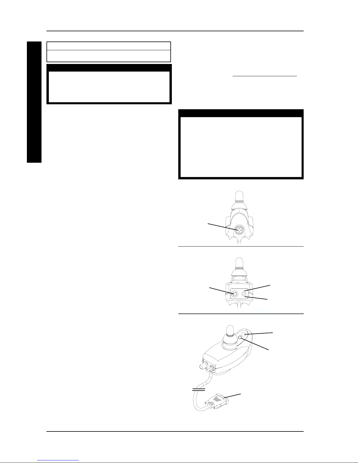
WHEELCHAIR OPERATION
Switches/Indicators (Figure 1)
The following switches and indicators are located
on the joystick housing:
ON/OFF SWITCH - The on/off switch is located on
the BACK of the joystick housing. This two (2) position toggle switch is used for turning the wheelchair
ON and OFF (DETAIL "B").
SPEED CONTROL KNOB - The speed control knob
is located on the BACK of the joystick housing. This
rotary knob is used for controlling the maximum
speed of the wheelchair. Turning the knob clockwise INCREASES the maximum speed of the wheelchair. Turning the knob counter-clockwise DECREASES the maximum speed of the wheelchair
(DETAIL "B").
BATTERY DISCHARGE INDICATOR (BDI) - The
battery discharge indicator is located at the FRONT
of the joystick housing. It provides information on
the remaining charge in the batteries. At full charge
the BDI will be Green. As the battery becomes discharged, the BDI will become Yellow (Amber), then
Red and finally the BDI will flash ON and OFF Red.
At this level, the user should charge the batteries as
soon as possible (DETAIL "C").
The BDI will flash ON and OFF Yellow to indicate a
reduced speed or power output.
The BDI also serves as a system diagnostic device
when a fault is detected by the control module. A
specific number of Green flashes will indicate the
type of fault detected. For more information on using the battery discharge indicator as a system diagnostic device, contact a qualified technician.
NOTE: When reading the Battery Discharge Indicator (BDI), the joystick MUST be in the NEUTRAL
position for an accurate reading.
W ARNING
After ANY adjustments, repair or service and
BEFORE use, make sure that all attaching
hardware is tightened securely - otherwise
injury or damage may result.
MULTI FUNCTION CHARGER PORT- The multi
function charger port is located at the front of the
joystick housing. It provides access for charging the
wheelchair batteries using an INDEPENDENT battery charger, refer to CHARGING BATTERIES in
PROCEDURE 8 of this manual. This port also serves
as the Remote Programmer/AVS communication
connection and is used for setting-up/programming
the electronic control unit (DETAIL "A").
WARNING
Set-up/programming of the Electronic Control Unit is to be performed ONL Y by a qualified technician. The fine tuning adjustments
of the controller may affect other activities of
the wheelchair. Damage to the equipment
could occur under these circumstances. If
unqulaified individuals perform any work on
these units, the warranty is voided.
FIGURE 1 - WHEELCHAIR OPERA TION -
SWITCHES/INDICA TORS
On Switch
Position
Battery
Discharge
Indicator
Off Switch
Position
DETAIL "A" - FRONT VIEW
DET AIL "B" - REAR VIEW
Multi-
Function
Charger
Port
Speed
Control
Knob
Horn
DET AIL "C"
To Controller
15
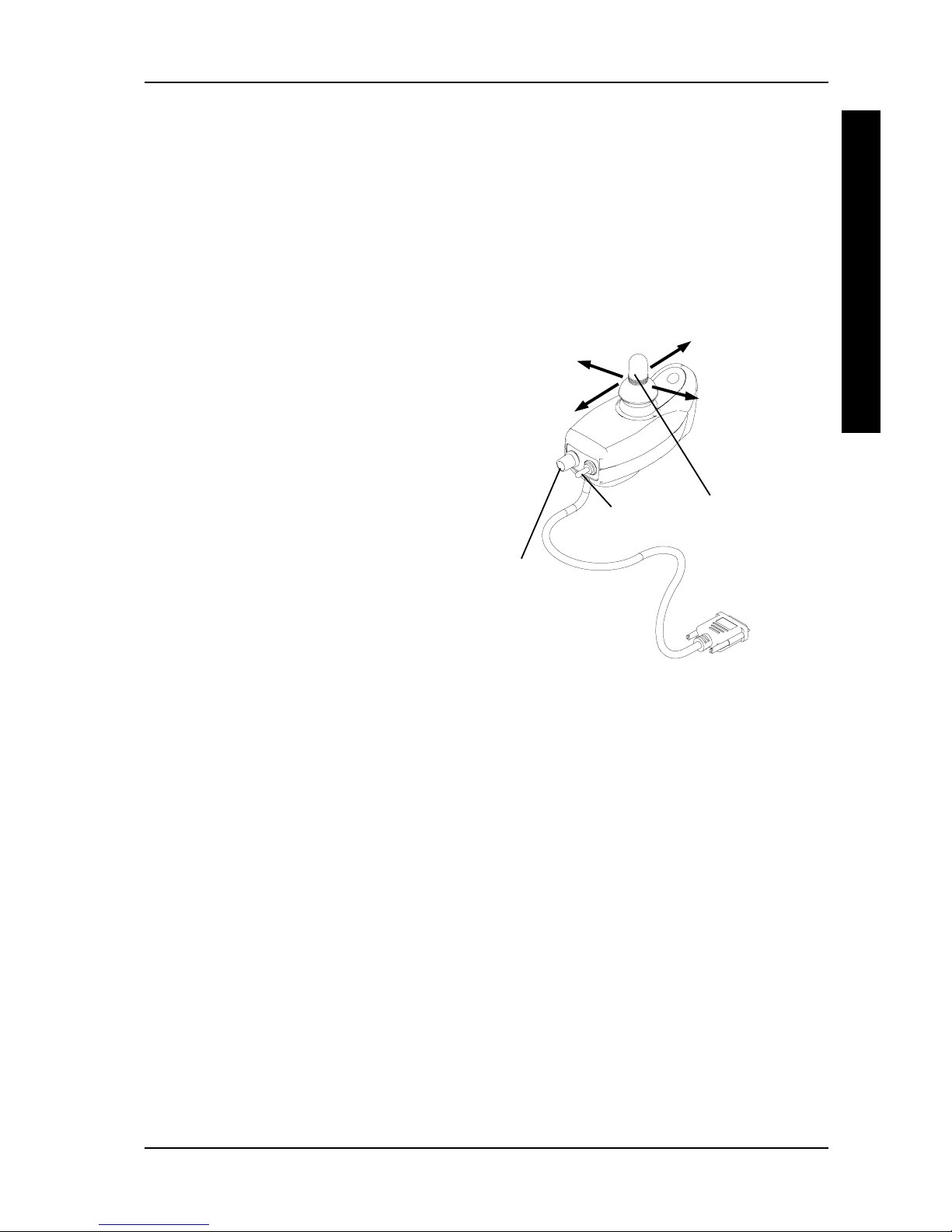
Using The Joystick To Drive The Chair
The joystick is located at the front of the joystick housing and provides smooth control of speed and direction. It is equipped with 360 degrees of mobility for
ease of operation. The joystick is spring-loaded, and
automatically returns to the upright (neutral) position
when released. Pushing the joystick in a given direction causes the chair to move in that direction.
The joystick has proportional drive control, meaning
that the further it is pushed from the upright (neutral)
position, the faster the wheelchair moves. Your top
speed, however, is limited by the setting of the speedcontrol knob.
To slow the wheelchair to a stop, simply release the
joystick. The wheelchair has automatic speed and
direction compensation to minimize corrections.
When first learning to drive, select a SLOW speed
and try to drive the wheelchair AS SLOWLY as
possible by pushing the joystick slightly forward.
This exercise will help you learn to utilize the full
potential of the proportional control and allow you
to start and stop smoothly.
To operate the wheelchair, perform the following:
1. Adjust speed control knob to the appropriate
setting.
2. Position the ON/OFF switch into the ON position.
3. Maneuver the joystick in the following manner:
FIGURE 2 - WHEELCHAIR OPERA TION - USING
THE JOYSTICK TO DRIVE THE CHAIR
To Move
Forward
To Move
Backward
To Move Right
To
Move
Left
ON/OFF
Switch
Speed
Control
Knob
Joystick
A. To move FORWARD - Push forward on the
joystick.
B. To move in REVERSE- Pull back on the
joystick.
C. To turn RIGHT- Move the joystick RIGHT.
D. To turn LEFT- Move the joystick LEFT.
E. To STOP - Release the joystick and the
wheelchair will quickly slow down.
W
H
E
E
L
C
H
A
I
R
O
P
E
R
A
T
I
O
N
WHEELCHAIR OPERA TION PROCEDURE 3
 Loading...