

Invacare Pronto R2 Series, Pronto R2-250 Series Servise Manual

Service Manual
Pronto
/Pronto
R2
R2-250 Series
DEALER: KEEP THIS MANUAL. THE PROCEDURES
IN THIS MANUAL MUST BE PERFORMED BY A
QUALIFIED TECHNICIAN.

WARNING/SPECIAL NOTES
THE PROCEDURES IN THIS MANUAL SHOULD ONLY BE PERFORMED
W
A
R
N
I
N
G
DO NOT SERVICE OR OPERATE THIS EQUIPMENT WITHOUT FIRST
READING AND UNDERSTANDING THIS MANUAL AND THE OWNER’S
MANUAL SUPPLIED WITH THE WHEELCHAIR. IF YOU ARE UNABLE TO
UNDERSTAND THE WARNINGS, CAUTIONS, AND INSTRUCTIONS,
CONTACT INVACARE TECHNICAL SUPPORT BEFORE ATTEMPTING TO
SERVICE OR OPERATE THIS EQUIPMENT - OTHERWISE INJURY OR
WARNING
BY A QUALIFIED TECHNICIAN.
DAMAGE MAY RESULT.
SPECIAL NOTES
S
P
E
C
A
L
N
O
T
E
S
WARNING/CAUTION notices as used in this manual apply to hazards or unsafe practices
which could result in personal injury or property damage.
NOTICE
I
THE INFORMATION CONTAINED IN THIS DOCUMENT IS SUBJECT TO CHANGE WITHOUT NOTICE.
WHEELCHAIR USER
As a manufacturer of wheelchairs, Invacare endeavors to supply a wide variety of
wheelchairs to meet many needs of the end user. However, final selection of the type of
wheelchair to be used by an individual rests solely with the user and his/her healthcare
professional capable of making such a selection.
WHEELCHAIR TIE-DOWN RESTRAINTS AND SEAT POSITIONING STRAPS
Invacare recommends that wheelchair users NOT be transported in vehicles of any kind
while in wheelchairs. As of this date, the Department of Transportation has not approved
any tie-down systems for transportation of a user while in a wheelchair, in a moving
vehicle of any type.
It is Invacare’s position that users of wheelchairs should be transferred into appropriate
seating in vehicles for transportation and use be made of the restraints made available
by the auto industry. Invacare cannot and does not recommend any wheelchair transportation systems.
AS REGARDS RESTRAINTS - SEAT POSITIONING STRAPS - IT IS THE OBLIGATION OF THE DME
DEALER, THERAPISTS AND OTHER HEALTHCARE PROFESSIONALS TO DETERMINE IF A SEATING
POSITIONING STRAP IS REQUIRED TO ENSURE THE SAFE OPERATION OF THIS EQUIPMENT BY
THE USER. SERIOUS INJURY MAY OCCUR IN THE EVENT OF A FALL FROM A WHEELCHAIR.
SAVE THESE INSTRUCTIONS
2

TABLE OF CONTENTS
NOTE: The following procedures refer to the ProntoR2 and the Pronto
SPECIAL NOTES................................................ 2
SPECIFICA TIONS ............................................... 4
PROCEDURE 1 - GENERAL GUIDELINES .......... 5
REPAIR OR SERVICE INFORMATION ................. 5
OPERATING INFORMATION ............................... 5
WARNING/CAUTION LABEL LOCATION ............ 6
PROCEDURE 2- TROUBLESHOOTING ............. 7
FIELD LOAD TEST ............................................ 7
USING HYDROMETER TO CHECK BATTERY
CELLS (LEAD ACID)....................................... 7
MOTOR TESTING ............................................. 8
MOTOR BRUSH INSPECTION ........................... 9
ELECTRO-MECHANICAL PARKING BRAKE
TESTING ....................................................... 9
PROCEDURE 3 - FRONT RIGGINGS ................ 10
ADJUSTING THE REMOVABLE FOOTBOARD .. 10
PROCEDURE 4 - ARMS .....................................11
REPLACING ARMREST PADS ...........................11
REPLACING ARMREST PLATE ......................... 11
PROCEDURE 5 - UPHOLSTERY/SEAT
POSITIONING STRAP ................................... 12
REPLACING SEAT POSITIONING STRAP .......... 12
REPLACING BACK UPHOLSTERY ................... 12
PROCEDURE 6 - SEA T/BACK........................... 14
CHANGING SEAT DEPTH ................................ 14
REPLACING CAPTAIN’S VAN SEAT AND OR
CAPTAIN’S VAN SEAT FRAME ..................... 15
REMOVING/INSTALLING STANDARD SEAT ..... 15
REMOVING/INSTALLING CAPTAIN’S
VAN SEAT ................................................... 16
REMOVING/INSTALLING SEAT PAN ................. 17
MOUNTING PLATE - SEAT ANGLE
ADJUSTMENT AND INSTALLATION
ORIENTATION ............................................ 17
CHANGING BACK HEIGHT .............................. 19
BACK ANGLE ADJUSTMENT .......................... 21
PROCEDURE 7 - ELECTRONICS ..................... 22
REPOSITIONING MKIV/RII JOYSTICK ................ 22
REMOVING/INSTALLING MKIV AND/OR
RII CONTROLLER ....................................... 22
PROCEDURE 8 - LIMIT SWITCH ...................... 27
ADJUSTING LIMIT SWITCH ............................... 27
PROCEDURE 9 - WHEELS ............................... 28
REPLACING PNEUMATIC TIRES/TUBES -
DRIVE WHEELS/CASTERS ......................... 28
REMOVING/INSTALLING DRIVE WHEELS ......... 28
REMOVING/INSTALLING DRIVE WHEEL HUB .. 29
REPLACING CASTERS ................................... 30
REPLACING FORKS ....................................... 30
PROCEDURE 10 - SHROUDS ........................... 32
REMOVING/INSTALLING SHROUDS .................. 32
PROCEDURE 11 - BATTERIES ........................ 34
INSTALLING/REMOVING BATTERIES
INTO/FROM BATTERY BOXES ................... 34
CONNECTING BATTERY CABLES .................. 35
WHEN TO CHARGE BATTERIES .................... 39
CHARGING BATTERIES .................................. 39
REPLACING BATTERIES ................................ 41
INSTALLING/REMOVING BATTERY BOXES ..... 41
REMOVING/INSTALLING BATTERY TRAY ........ 42
PROCEDURE 12 - BASE FRAME` .................... 44
REPLACING WIRING HARNESS ..................... 44
ADJUSTING STABILIZER ASSEMBLY
FOR USER PREFERENCE ........................ 46
REPLACING STABILIZER CYLINDERS .............. 46
REPLACING STABILIZER WHEEL ..................... 47
REPLACING CLUTCH HANDLE ........................ 47
REPLACING MOTOR/GEARBOX . .. .. .... .. .. .... .. .. . 48
REPLACING SEAT MOUNT PLATES ................ 49
REPLACING SEAT SUPPORT BRACKETS ..... 50
REPLACING SEAT SUPPORT BRACKET
T-NUTS ...................................................... 51
REPLACING BATTERY CHARGER BRACKET
AND T-NUT ................................................. 51
PROCEDURE 12 - RECLINER .......................... 53
POSITIONING LIMIT SWITCH .......................... 53
ADJUSTING LIMIT SWITCH ............................. 53
REPLACING RECLINER CABLE ASSEMBLIES 54
REPLACING/ADJUSTING GAS CYLINDERS ..... 55
CHANGING BACK HEIGHT .............................. 56
CHANGING SEAT DEPTH ............................... 57
CHANGING SEAT WIDTH ................................ 57
INSTALLING/REPLACING ADJUSTABLE
16 TO 19-INCH DEEP RECLINER
SEAT FRAME .............................................. 58
R2-250 Series
TABLE OF CONTENTS
.
T
A
B
L
E
O
F
C
O
N
T
E
N
T
S
LIMITED W ARRANTY ....................................... 59
3

SPECIFICATIONS
SPECIFICATIONS
S
P
E
C
F
C
A
T
O
N
S
I
Seat Width Range:
Seat Depth Range:
I
Back Height Range Std.:
W/Optional Headrest:
I
W/Optional Backrest Ext.:
Back Angle Range:
Seat-to-Floor:
Overall Width (No joystick):
Overall Height:
Weight:
W/O Batteries:
W/Batteries (Gel Cell):
Shipping:
Armrests:
Upholstery:
CAPTAIN'S SEA T BACK ANGLE RECLINER SEAT
BACK TYPE
LOW LOW SOLID SEAT HIG H
(LOB) (LOBSS) (HIB)
19.5-in. 19.5-in. 19.5-in.
17.5-in. 17.5-in. 17.5-in.
16-in. 16-in. 20-in.
N/A N/A 29.0-in.
23.5-in. 23.5-in. N/A
o
(85
-114o) (98o) (85o-170o)
23-in. 20-in. 23-in.
25.5-in. 25.5-in. 25.5-in.
37-in. 37-in. 41.5-in.
142-lbs
216-lbs.
266-lbs.
Removable, Flip Back, Fixed or
Adjustable Height - Desk and Full Length
Gray Cloth, Grey Vinyl, Tan Vinyl
ADJUSTABLE SEA T
16-24-inches
16-22 inches - in 1-inch
increments
16-24 inches - In 1-inch
increments
N/A
N/A
o
80
to 100o - in 5
increments
18.5-inches
24.75 -inches
34.50 -in. - 42.50-in. Back
Height
143 lbs.
217 lbs.
267 lbs.
Removable, Flip Back,
Fixed or Adjustable Height
- Desk and Full Length
Black Nylon
o
16-24-inches
16-22 inches - in 1-inch
increments
18-26 inches - In 2-inch
increments
29-37 inches - in 1-inch
increments
N/A
o
90
to 170o - continuous
18.5-inches
24.75 -inches
36.50 -in. - 44.50-in. Back
Height
151 lbs.
225 lbs.
275 lbs.
Removable, Flip Back,
Fixed or Adjustable Height
- Desk and Full Length
Black Nylon
CAPT AIN'S SEAT/ADJUST ABLE SEA T BACK ANGLE/RECLINER
Overall Length (
Refer to PERCENTAGE OF WEIGHT DISTRIBUTION
in PROCEDURE 1 of this manual.)
Front Stabilizers
Drive Wheels/Tires:
Casters w/Precision Sealed
Bearings:
Footrest/Legrest:
Battery/Size (Not Supplied):
PERFORMANCE
Speed (M.P.H.):
T urning Radius:
Range (variable)1:
Weight Limitation
2, 3
:
7-inch Urethane
12-1/2 x 2-1/4-in. (Std.); 14-in.x 3-in. (Opt.) (Flat Free or Pneumatic)
8 x 1-3/4-in. Semi Pneumatic (Std.), 8 x 2-in. Pneumatic (Opt.)
6 x 2-in. Semi Pneumatic (Opt.)
Swingaway, Removable Footboard
ProntoR2 uses 22NF Gel Cell/Pronto
CAPT AIN'S SEAT/ADJUST ABLE SEA T BACK ANGLE/RECLINER
0 to 3.6 (250 lb. Limit), 0 to 5.5 (300 lb. Limit), 0 - 3.8 (400 lb. Limit)
> 23-inches (With Removable Footboard)
17 miles
250 lbs., 300 lbs., or 400 lbs. (See FOOTNOTE 3)
47.5-inches 34.0-inches
(With 8-in. rear casters (With 8-in. rear casters
and 93 front riggings) and no front riggings)
Footnotes:
1. Range will vary with battery conditions, surface, terrain and operators weight.
2. Includes seating systems and accessories.
R2-250 Series
uses U1 Gel Cell
3. Weight limitation varies with motor. Refer to
LIMITATION - GENERAL WARNINGS in PROCEDURE 1 of this manual.
WEIGHT
4

GENERAL GUIDELINES PROCEDURE 1
This Procedure Includes the Following:
Repair or Service Information
Operating Information
WARNING
REPAIR OR SERVICE INFORMATION
Set-up of the Electronic Control Unit is to be performed ONLY by Invacare dealers. The
final tuning adjustments of the controller may affect other activities of the wheelchair.
Damage to the equipment could occur under these circumstances. If any individual
other than a qualified technician performs any work on these units, the warranty is void.
OPERATING INFORMATION
GENERAL WARNINGS
Performance adjustments should only be made by professionals of the healthcare field
or persons fully conversant with this process and the driver's capabilities. Incorrect settings could cause injury to the driver, bystanders, damage to the chair and to surrounding
property.
After the wheelchair has been set-up, check to make sure that the wheelchair performs
to the specifications entered during the set-up procedure. If the wheelchair does NOT
perform to specifications, turn the wheelchair OFF immediately and reenter set-up specifications. Repeat this procedure until the wheelchair performs to specifications.
DO NOT use parts, accessories, or adapters other than those authorized by Invacare.
TIRE PRESSURE
DO NOT use your wheelchair unless it has the proper tire pressure (P.S.I.). DO NOT overinflate the tires. Failure to follow these suggestions may cause the tire to explode and
cause bodily harm. The recommended tire pressure is listed on the side wall of the tire.
G
E
N
E
R
A
L
G
U
I
D
E
L
I
N
E
S
BATTERIES
The warranty and performance specifications contained in this manual are based on
the use of deep cycle gel cell or sealed lead acid batteries. Invacare strongly recommends their use as the power source for this unti.
The use of rubber gloves and safety glasses is recommended when working with batteries.
Carefully read battery/battery charger information prior to installing, servicing or operating your wheelchair.
ELECTRICAL
Grounding Instructions:
DO NOT, under any circumstances, cut or remove the round grounding prong from any
plug used with or for Invacare products. Some devices are equipped with three-prong
(grounding) plugs for protection against possible shock hazards. Where a two-prong wall
receptacle is encountered, it is the personal responsibility and obligation of the customer
to contact a qualified electrician and have the two-prong receptacle replaced with a
properly grounded three-prong wall receptacle in accordance with the National Electrical Code. If you must use an extension cord, use ONLY a three-wire extension cord
having the same or higher electrical rating as the device being connected. In addition,
Invacare has placed RED/ORANGE WARNING TAGS on some equipment. DO NOT remove these tags. Carefully read battery/battery charger information prior to installing,
servicing or operating your wheelchair.
5
GENERAL GUIDELINESPROCEDURE 1
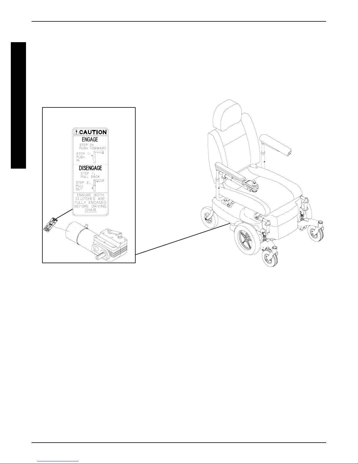
WARNING/CAUTION LABEL LOCATION
G
E
N
E
R
A
L
G
U
I
D
E
L
I
N
E
1074126
6
TROUBLESHOOTING PROCEDURE 2
This Procedure Includes the Following:
Field Load Test
Using Hydrometer To Check Battery Cells (Lead
Acid)
Motor Testing
Motor Brush Inspection
Electro-Mechanical Parking Brake Testing
FIELD LOAD TEST (FIGURE 1)
NOTE: The following test can also be performed through
the controller of the wheelchair along with a remote programmer. Refer to the individual CONTROLLER
MANUAL supplied with each wheelchair.
Old batteries lose their ability to store and release power,
due to increased internal resistance. This means that as
you try to take power from the battery, some of that power
is used up in the process of passing through the battery,
resulting in less voltage at the posts. The more power
drawn, the lower the voltage available. When this lost voltage drops the output 1.0 volts under load (2.0 for a pair),
replace the batteries.
Testing under load is the only way to spot this problem.
While special battery load testing equipment is available,
it is costly and difficult to transport.
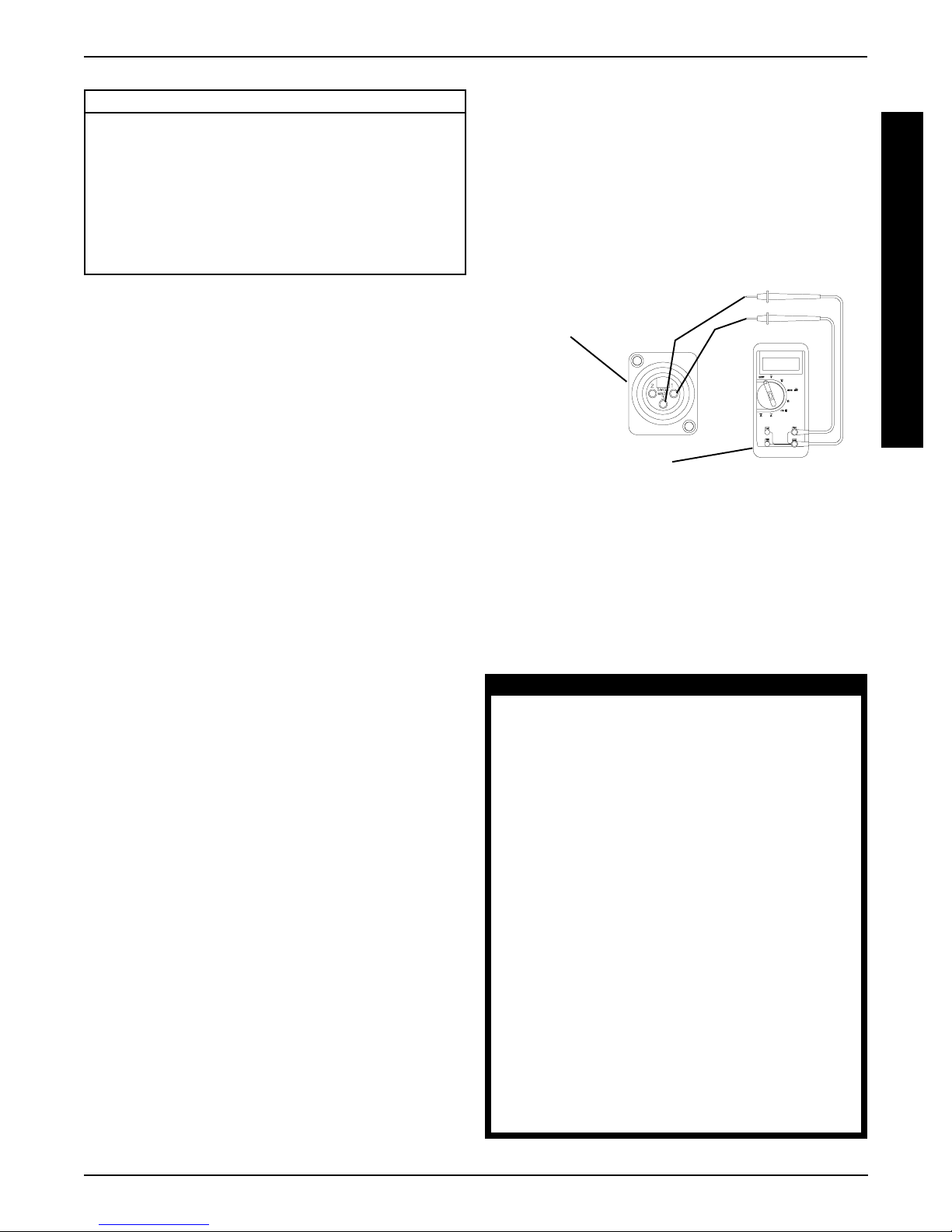
Use a digital voltmeter to check battery charge level at the
charger connector. It is located on the base of the wheelchair frame.
NOTE: READ the instructions CAREFULLY before using the digital voltmeter.
NOTE: Invacare recommends that ONL Y qualified technicians perform this test.
1. Ensure that power is OFF.
2. Make sure battery is fully charged. An extremely discharged battery will exhibit the same symptoms as a
bad one.
3. Place one (1) piece of wood taller than the axle of the
drive wheels between the wheelchair and a wall, workbench or other stationary object.
4. Remove the footrests or footboard from the wheelchair and place the stabilizer wheels against the piece
of wood.
5. Place the voltmeter leads into the charger plug on the
wheelchair. Most digital voltmeters are not affected by
polarity, however, analog meters (meters with swinging needles) can be and should be used carefully. A
good meter reading should be 25.5 to 26 VDC.
6. Have two (2) individuals (one [1] on each arm) apply
as much downward pressure as possible on the arms
of the wheelchair.
7. Turn the wheelchair ON and push the joystick forward, trying to drive the wheelchair through the stationary object. This puts a heavy load on the batteries
as they try to push through the stationary object. Read
the meter while the motors are straining to determine
the voltage under load.
NOTE: If the voltage drops to less than 23.5 volts from a
pair of fully charged batteries while under load, they should
be replaced regardless of the unloaded voltages.
Battery Charger
(-)
Connector
(+)
Digital Voltmeter
FIGURE 1 - FIELD LOAD TEST
USING HYDROMETER TO CHECK
BATTERY CELLS (LEAD ACID)
(FIGURE 2)
NOTE: Perform this procedure when a digital voltmeter is
not available.
WARNING
NEVER smoke or strike a match near the
batteries. If the caps of the battery cells
are removed, NEVER look directly into
them when charging the battery.
The use of rubber gloves and safety glasses
is recommended when testing the battery
cells.
When reading a hydrometer, DO NOT allow any liquid to come in contact with
your eyes or skin. It is a form of acid and
can cause serious burns, and in some
cases, blindness. If you do get battery acid
on you, flush the exposed areas with cool
water IMMEDIATELY. If the acid comes into
contact with eyes or causes serious burns,
get medical help IMMEDIATELY.
The battery acid can damage your wheelchair, clothing, and household items.
Therefore, take readings cautiously and
only in designated areas.
T
R
O
U
B
L
E
S
H
O
O
T
I
N
G
7
TROUBLESHOOTINGPROCEDURE 2
WARNING
ONLY use distilled water when topping off
T
R
O
U
B
L
E
S
H
O
O
T
I
N
G
the battery cells.
Most batteries are not sold with instructions.
However, warnings are frequently noted
on the cell caps. Read them carefully.
1. Remove the battery box(es). Refer to
MOVING BATTERY BOXES in PROCEDURE 11 of
this manual.
2. Remove the battery caps from the battery.
3. Squeeze the air from the hydrometer.
4. Place the hydrometer into a battery cell.
NOTE: DO NOT fill hydrometer more than 3/4 full.
5. Draw up sufficient acid to cover float balls.
6. Tap lightly to remove air bubbles.
7. Number of floating balls indicates charge.
Number of Floating Balls
INSTALLING/RE-
9. Flush hydrometer in cold running water by allowing
the water to rise into hydrometer as far as possible.
Do this several times to guard against burn damage.
10. Replace the battery caps.
11. Reinstall battery boxes. Refer to
INSTALLING/REMOV-
ING BATTERY BOXES in PROCEDURE 11 of this
manual.
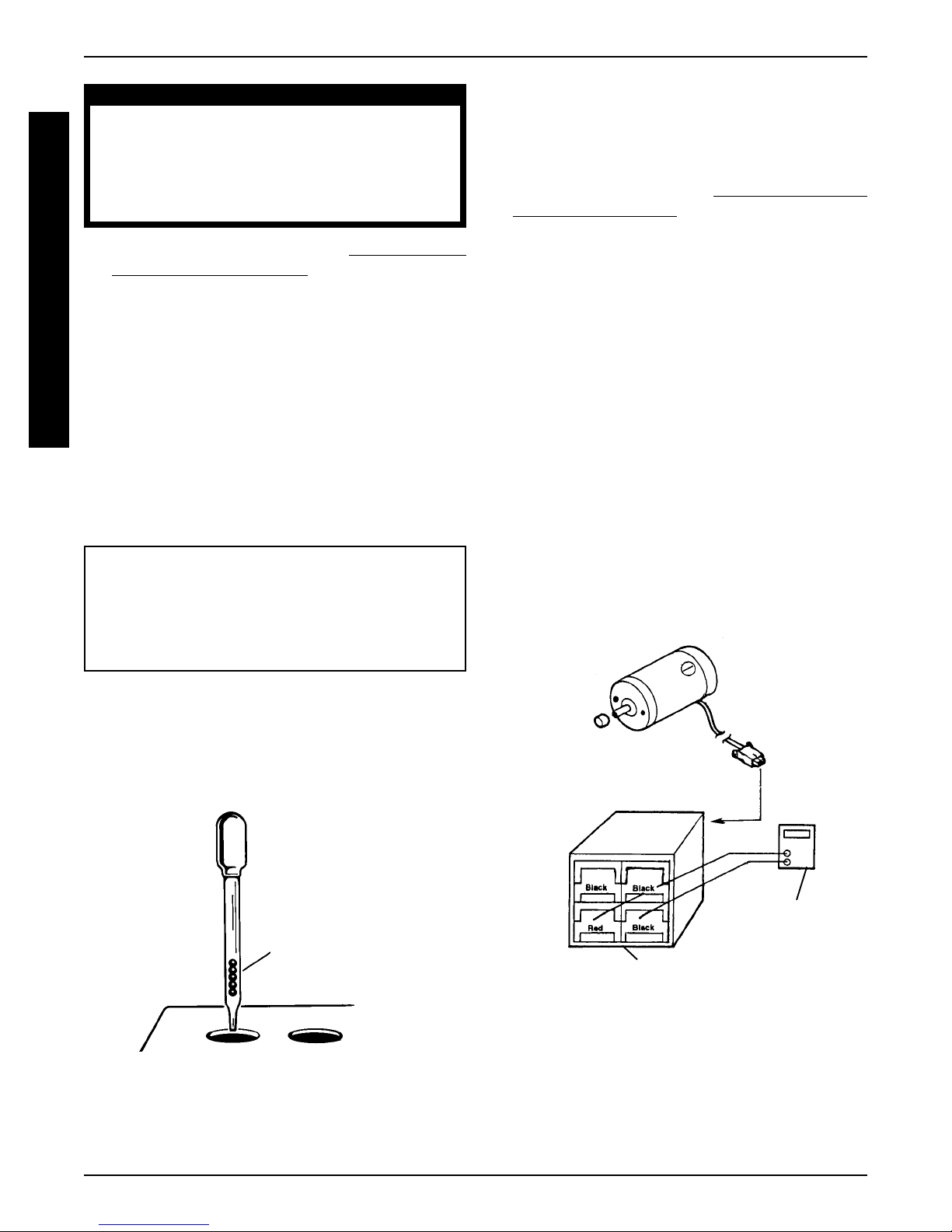
MOTOR TESTING (FIGURE 3)
1. On the 4-pin motor connector, locate the two (2) contacts in the red and black housings.
2. Set the digital multimeter to measure ohms (Ω).
3. Measure the resistance between the two (2) motor
contacts.
NOTE: A normal reading is between 1 and 5 ohms
(
Ω
). A reading of 0 ohms (Ω) or in excess of 15 ohms
(Ω) indicates a problem. High readings are generally
caused by bad connections and/or damaged brushes.
Contact Invacare Dealer.
0 Discharged
1 25% Charged
2 50% Charged
3 75% Charged
4 100% Charged
* 5 Overcharged
* Check charging system.
8. Flush the liquid back into the same cell after reading the
float. Repeat this step until all cells have been properly
read. A shorted or dead cell can be detected when it is
the only cell that does not charge.
Number of Floating
Balls Will Vary
According to Charge
Ohmmeter
Motor Connector
FIGURE 3 - MOTOR TESTING
FIGURE 2 - USING A HYDROMETER TO
CHECK BATTERY CELLS (LEAD ACID)
8
TROUBLESHOOTING PROCEDURE 2
MOTOR BRUSH INSPECTION
(FIGURE 4)
There are two (2) contact brushes on the motors located
under the brush caps on the motor housing. If these caps
are hard to remove they are either overtightened or the
motor has become very hot. Let motors cool. If caps still
cannot be removed, it is recommended that the motor be
sent to Invacare Technical Services for inspection/repair.
NOTE: It is very important to note which way the brush
comes out of the motor. The brush MUST be placed into
the motor exactly the same way to ensure good contact
with the commutator.
1. Once the motor brush caps have been removed, pull
the brushes out of the motor. The end of the brushes
should be smooth and shiny and the spring should
not be damaged or discolored. If one or both of the
brushes are damaged, only the damaged or worn
brushes need be replaced. It is very important that
any time a brush is replaced, it must be “burned in”.
This is accomplished by running the motor for one
hour in each direction with a half hour break in-between. This should also be done with little or no load
on the motor, i.e., put the wheelchair up on blocks so
the drive (large) wheels do not contact the ground
and run the wheelchair. A motor with only one brush
replaced will only carry a small percentage of its rated
load capacity until the NEW brush is burned in.
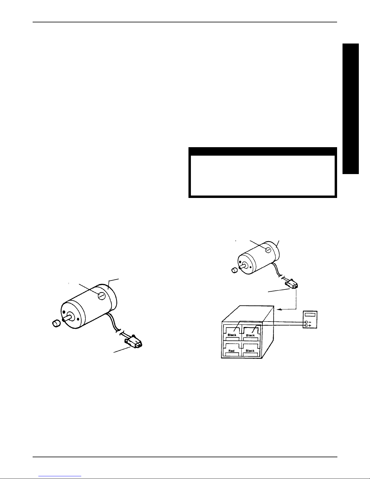
ELECTROMECHANICAL PARKING
BRAKE TESTING (FIGURE 5)
1. On the four-pin motor connector, locate the side by
side connectors in the black housings.
2. Set the digital multimeter to read ohms (Ω).
3. Measure the resistance between the two (2) brake
contacts. A normal reading is 100 ohms (Ω). A reading of 0 ohms (Ω) or a very high reading; i.e., MEG
ohms or O.L. (out of limit) indicates a shorted brake
or an open connection respectively. If either condition
exists, send the motor to Invacare Technical Service
for inspection/repair.
CAUTION
A shorted electromechanical brake will
damage the brake output section in the controller. DO NOT connect a shorted electromechanical brake to a good controller module. A shorted brake MUST be replaced.
NOTE: A bad motor can damage the controller module
but a bad controller should NOT damage a motor.
Cap
Motor
T
R
O
U
B
L
E
S
H
O
O
T
I
N
G
Cap
Motor
4 Pin Motor Connector
FIGURE 4 - MOTOR BRUSH INSPECTION
4 Pin Motor Connector
Ohmmeter
FIGURE 5 - ELECTROMECHANICAL PARKING
BRAKE TESTING
9
PROCEDURE 3
FRONT RIGGINGS
This Procedure Includes the Following:
Adjusting the Removable Footboard Height
F
R
O
N
T
R
After ANY adjustments, repair or service
and BEFORE use, make sure that all attaching hardware is tightened securely - otherwise injury or damage may result.
WARNING
I
G
ADJUSTING THE REMOVABLE
G
FOOTBOARD HEIGHT (FIGURE 1)
I
1. Remove the removable footboard plate. Refer to
N
G
S
REMOVING/INSTALLING THE REMOVABLE
FOOTBOARD ONTO/FROM THE WHEELCHAIR
in PROCEDURE 3 of the Owner’s Manual, part number 1096502.
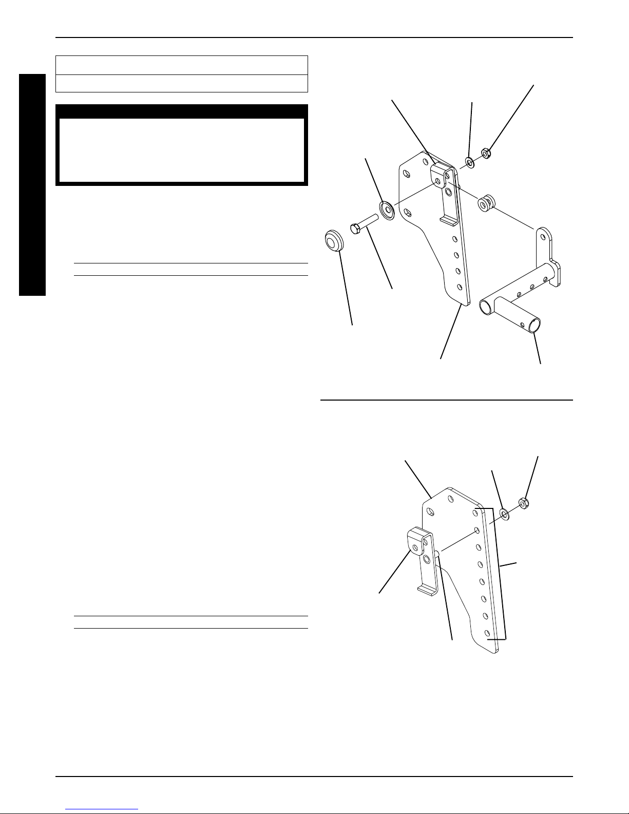
2. Remove the caplug cap.
3. Remove the mounting screw, caplug washer, flat
washer and nut that secures the two (2) large washers and support tube to the height adjustment bracket
and footboard bracket. Refer to DETAIL “A”.
4. Remove the nut and flat washer that secure the threaded
arm on the height adjustment bracket to the footboard
bracket. Refer to DETAIL “B”.
5. Move the height adjustment bracket to one (1) of seven
(7) height positions.
6. Reinstall the flat washer and nut that secures the threaded
arm on the height adjustment bracket to the footboard
bracket. Refer to DETAIL “B”.
DETAIL “A”
Bracket
Caplug
Washer
Mounting
Screw
Caplug
Cap
Footboard
Bracket
DETAIL “B”
Footboard Bracket
Flat
Washer
Flat
Washer
NutHeight Adjustment
Two (2) Large
Washers
Support Tube
Nut
7. Reinstall the mounting screw, caplug washer, flat
washer and nut that secures the two (2) large washers and support tube to the height adjustment bracket
and footboard bracket. Refer to DETAIL “A”.
8. Reinstall the caplug caps.
9. Repeat STEPS 2-8 for the opposite footboard bracket.
10. Reinstall the removable footboard plate. Refer to
REMOVING/INSTALLING THE REMOVABLE
FOOTBOARD ONTO/FROM THE WHEELCHAIR
in PROCEDURE 3 of the Owner’s Manual.
Mounting
Positions
Height
Adjustment
Bracket
Threaded
Arm
FIGURE 1 - ADJUSTING THE
REMOVABLE FOOTBOARD HEIGHT
10
ARMS PROCEDURE 4
This Procedure Includes the Following:
Replacing Armrest Pads - Captain's van Seats
Replacing Captain's van Seat Armrest Plate
WARNING
After ANY adjustments, repair or service
and BEFORE use, make sure that all attaching hardware is tightened securely - otherwise injury or damage may result.
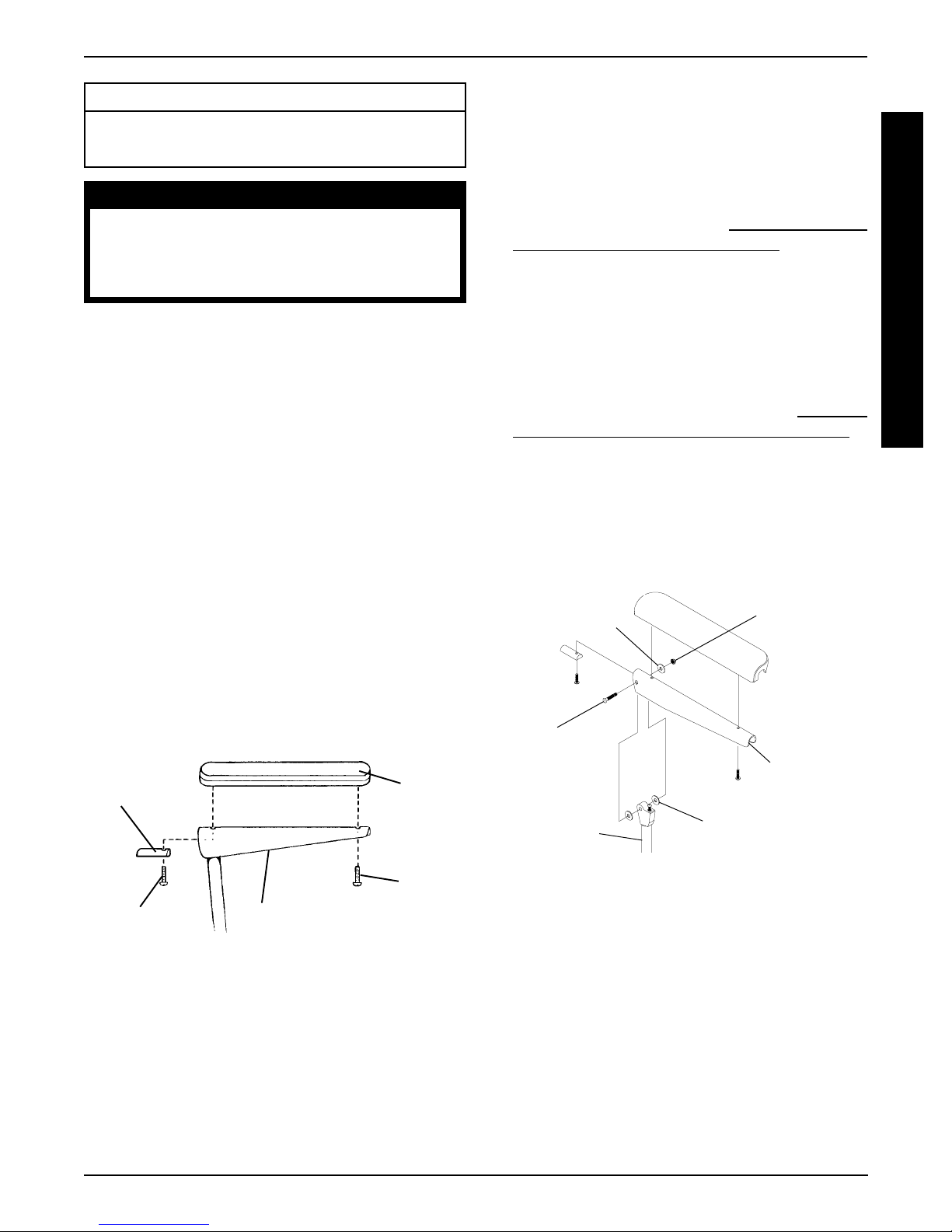
REPLACING ARMREST PADS CAPTAIN'S VAN SEATS (FIGURE 1)
1. Remove the mounting screw that secures the front
of the armrest pad to the armrest plate.
2. Remove the mounting screw that secures the rear of
the armrest pad and armrest insert to the armrest
plate.
3. Remove the existing armrest pad and position the
NEW armrest pad on the armrest plate.
4. Line up the mounting holes in the armrest insert, armrest plate and NEW armrest pad.
REPLACING CAPTAIN'S VAN SEAT
ARMREST PLATE (FIGURE 2)
1. If necessary, remove the three (3) mounting screws,
spacers and locknuts that secure the joystick mounting bracket to the armrest plate.
2. Remove armrest pad. Refer to
REST PADS - CAPTAIN'S VAN SEATS in this procedure of the manual.
3. Remove the mounting screw, washers and locknut that
secure the existing armrest plate to the arm weldment.
4. Position the NEW armrest plate on the armrest weldment
and secure with the mounting screw, washers, and locknut. Refer to FIGURE 2 for correct hardware orientation.
5. Reinstall van style armrest pad. Refer to
ING ARMREST PADS - CAPTAIN'S VAN SEAT in
this procedure of the manual.
6. If necessary, reinstall the three (3) mounting screws,
spacers and locknuts that secure the joystick mounting bracket to the armrest plate.
7. Repeat STEPS 1-6 for the opposite armrest plate, if
necessary.
REPLACING ARM-
REPLAC-
A
R
M
S
5. Reinstall the rear mounting screw through the armrest insert, armrest plate and armrest pad and tighten
securely.
6. Reinstall the front mounting screw into the armrest
plate and NEW armrest pad and tighten securely.
FRONTREAR
Armrest
Insert
Mounting
Screw
FIGURE 1 - REPLACING ARMREST PADS -
CAPTAIN'S VAN SEATS
Armrest Plate
Armrest
Pad
Mounting
Screw
Washer
Mounting
Screw
Arm
Weldment
FIGURE 2 - REPLACING CAPTAIN'S VAN SEAT
ARMREST PLATE
Washer
Locknut
Armrest
Plate
11
UPHOLSTERY/POSITIONING STRAPPROCEDURE 5
This Procedure Includes the Following:
Replacing Seat Positioning Strap - Captain's Van
Seats
Replacing Back Upholstery
U
P
H
O
L
S
T
After ANY adjustments, repair or service
and BEFORE use, make sure that all attaching hardware is tightened securely - otherwise injury or damage may result.
WARNING
E
REPLACING SEAT POSITIONING
R
Y
STRAP - CAPTAIN'S VAN SEATS
(FIGURE 1)
1. Remove the van style seat from the van seat frame.
Refer to INSTALLING/REMOVING CAPTAIN'S VAN
P
O
S
I
T
I
O
N
I
N
G
S
T
R
A
P
SEAT ASSEMBLY in PROCEDURE 6 of this manual.
2. Remove the two (2) rear mounting screws, washers,
and locknuts that secure the seat positioning straps
to the van seat frame.
NOTE: The washer is positioned between the seat positioning strap and the mounting screw.
3. Secure the NEW seat positioning strap halves with
the mounting screws, washers and locknuts to the
van seat frame and torque to 75-inch pounds.
4. Reinstall the van style seat to the van seat frame.
Refer to
SEAT ASSEMBLY in PROCEDURE 6 of this manual.
INSTALLING/REMOVING CAPTAIN'S VAN
Van Seat Frame
Seat Positioning
Strap
REAR OF SEAT
FRAME
Mounting
Screw
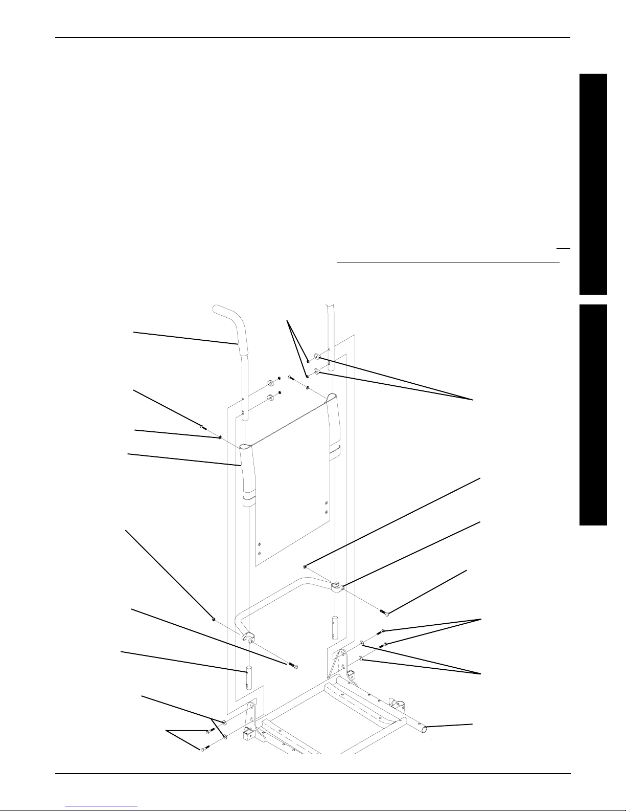
REPLACING BACK UPHOLSTERY
(FIGURE 2)
1. Remove one (1) armrest from the wheelchair. Refer to
INSTALLING/REMOVING FLIP BACK ARMRESTS in
PROCEDURE 4 of the Owner’s Manual, part number
1095602.
2. If applicable, remove the two (2) mounting screws
and locknuts that secure the spreader bar to the back
canes.
3. Remove the two (2) mounting screws and washers
that secure the existing back upholstery to the back
canes.
4. Cut the tie-wraps that secure the bottom of the existing back upholstery to the back canes.
NOTE: Note the back angle before disassembly for proper
reinstallation.
5. On the side of the wheelchair that the armrest was
removed, remove one (1) of the mounting screws,
washer, spacer, and locknut that secures the back
cane to the seat frame.
NOTE: To avoid losing the insert in each back cane, thread
the mounting screw just removed through the cane from
the inside of the wheelchair to hold the insert in place.
6. Remove the other mounting screw, washer, spacer,
and locknut that secures the back cane to the seat
frame.
7. Slide the back cane out of the spreader bar (If applicable) and the existing back upholstery.
8. Remove other armrest from the chair. Refer to
STALLING/REMOVING FLIP BACK ARMRESTS in
PROCEDURE 4 of the Owner’s Manual, part number 1095602.
9. Repeat STEPS 5-7 for the opposite side of the wheelchair.
10. Slide the other back cane out of the spreader bar (if
applicable) and the existing back upholstery.
IN-
Locknuts
Washer
FIGURE 1 - REPLACING SEAT POSITIONING
STRAP - CAPTAIN'S VAN SEATS
Loctite - Registered trademark of Loctite Corporation.
FRONT OF SEAT
FRAME
11. Slide one(1) back cane into NEW back upholstery
and through spreader bar (if applicable).
12. Secure back cane to the seat frame from the outside
of the wheelchair with the existing two (2) mounting
screws, washers, spacers, and locknuts. Use Loctite
242 and torque to 75-in/lbs.
13. Repeat STEPS 11-12 for opposite back cane.
14. Secure the top of the NEW back upholstery to the
back canes with the two (2) existing mounting screws.
12
UPHOLSTERY/POSITIONING STRAP PROCEDURE 5
NOTE: When replacing the back upholstery, back assembly or changing back height, follow these guidelines
for spreader bar height:
STANDARD MODELS
BACK HEIGHT K SPREADER BAR
HEIGHT
16-inches* 5-inches
17-inches* 5-inches
18-19-inches* 7-inches
20-24-inches 7-inches
NOTE: Spreader Bar required on ALL back heights
between 20-24-inches. *Spreader bar required on back
heights 16,17,18, or 19 ONLY if the width or depth of
the chair exceeds 19-inches.
KHeight of Spreader Bar from Bottom of Back
Canes to Top of Spreader Bar Clamp.
Locknuts
Back Cane
(STEPS 3, 12)
Mounting
Screw
(STEPS 3, 14)
Washer
(STEPS 3, 14)
Back
Upholstery
(STEPS 3, 7)
Locknut
(STEP 2)
(STEPS 5, 6)
HEAVY DUTY MODELS
NOTE: Spreader bar required on all back heights.
BACK HEIGHT K SPREADER BAR
HEIGHT
16-17-inches 5-inches
18-24-inches 7-inches
KHeight of Spreader Bar from Bottom of Back
Canes to Top of Spreader Bar Clamp.
15. If applicable, reposition the spreader bar at the correct
height for the corresponding back height and torque
the mounting hardware to 60-in/lbs.
16. Reinstall the armrest onto the wheelchair. Refer to INSTALLING/REMOVING FLIP BACK ARMRESTS in
PROCEDURE 4 of the Owner’s Manual, part number
1095602.
Spacers
(STEPS 5, 6)
Locknut
(STEP 2)
Spreader Bar
(STEPS 2, 7, 16)
U
P
H
O
L
S
T
E
R
Y
P
O
S
I
T
I
O
N
I
N
G
S
T
R
A
P
Mounting
Screw
(STEP 2)
Insert
Washers
(STEPS 5, 6)
Mounting Screws
Torque to 75 in/lbs
(STEPS 5, 6)
FIGURE 2 - REPLACING BACK UPHOLSTERY
Mounting Screw
Torque to 60 in/lbs
(STEP 2)
Mounting
Screws
(STEPS 5, 6)
Washers
(STEPS 5, 6)
Seat Frame
13
PROCEDURE 6 SEAT/BACK
This Procedure includes the following:
Changing Seat Depth For Standard Seat Frame
Replacing Captain's van Seat and/or Captain's van
S
E
A
T
B
A
C
K
Seat Frame
Removing/Installing Standard Seat
Removing/Installing Captain’s Van Seat
Removing/Installing Seat Pan
Mounting Plate - Seat Angle Adjustment and
/
Installation Orientation
Changing Back Height
Back Angle Adjustment
WARNING
After ANY adjustments, repair or service and
BEFORE use, make sure that all attaching
hardware is tightened securely - otherwise
injury or damage may result.
NOTE: The procedures in this section of the manual refer to
NON-RECLINER seat frames only, EXCEPT Seat Angle
Adjustment. For recliner seat frames, refer to PROCEDURE
14 of this manual.
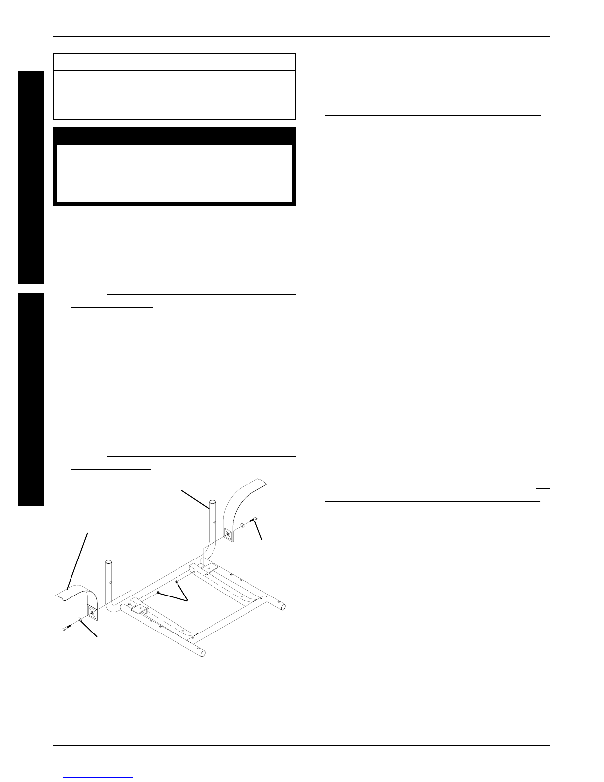
CHANGING SEAT DEPTH FOR
STANDARD SEAT FRAME (FIGURE 1)
7. Remove the seat pan (including seat positioning straps).
Refer to
cedure of the manual.
8. Remove the back upholstery (including back canes and
spreader bar, if applicable). Refer to
UPHOLSTERY in PROCEDURE 5 of the manual.
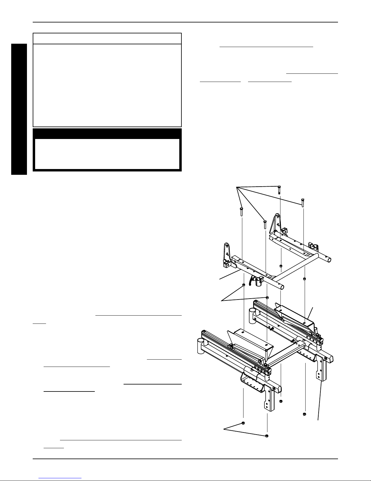
9. Remove the four (4) mounting screws, locknuts and
spacers, if applicable, that secure the standard seat frame
to the seat mounting plates.
10. Remove existing standard seat frame.
11. Position NEW standard seat frame on seat mounting
plates.
12. Secure NEW standard seat frame onto seat mounting
plates with existing four (4) mounting screws, locknuts
and spacers, if applicable. Torque to 156-inch pounds.
13. Reassemble wheelchair by reversing STEPS 1-8.
Mounting Screws
(Torque to 156-
inch pounds)
REMOVING/INSTALLING SEAT PAN in this pro-
REPLACING BACK
NOTE: The seat depth of the wheelchair can be adjusted up to
1-inch from the original seat depth by simply using the correct
depth seat pan without changing the seat frame. Example:
SEA T FRAME A VAILABLE SEA T DEPTHS
16-inch 16 and 17-inch
18-inch 18 and 19-inch
20-inch 20 and 21-inch
22-inch 22-inch
NOTE: If the desired seat depth change only requires a
NEW seat pan, refer to REMOVING/INSTALLING SEAT
PAN in this procedure. If the desired seat depth change requires a change in the seat frame, perform the following
1. Remove footrest assemblies. Refer to PROCEDURE
3 in the Owner’s Manual, part number 1095602.
2. Remove front and rear shrouds. Refer to
INSTALLING SHROUDS in PROCEDURE 10 of this
manual.
3. Remove battery box(es). Refer to
ING BATTERY BOX in PROCEDURE 11 of this manual.
4. Cut tie wraps and disconnect joystick from controller.
5. Turn the lever on the adjustment lock to release the adjustment lock from the joystick mounting tube.
6. Remove the flip-back armrests from the wheelchair. Re-
INSTALLING/REMOVING FLIP BACK ARM-
fer to
RESTS in PROCEDURE 4 of the Owner’s Manual,
part number 1095602.
INSTALLING/REMOV-
REMOVING/
Standard
Seat Frame
Spacer
(16-inch Wide
Only)
Locknuts
FIGURE 1 - CHANGING SEAT DEPTH FOR
STANDARD SEAT FRAME
Base Frame
Seat
Mounting
Plate
14
PROCEDURE 6SEAT/BACK
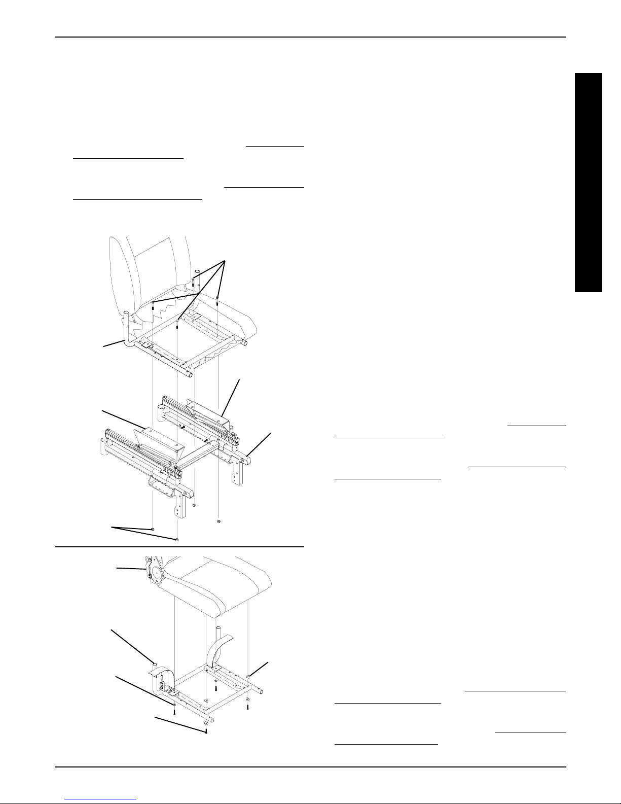
REPLACING CAPTAIN'S VAN SEAT
AND/OR CAPTAIN'S VAN SEAT
FRAME (FIGURE 2)
1. Remove footrest assemblies. Refer to PROCEDURE
3 of the Owner’s Manual, part number 1095602.
2. Remove front and rear shrouds. Refer to
INSTALLING SHROUDS in PROCEDURE 10 of this
manual.
3. Remove battery box(es). Refer to
MOVING BATTERY BOXES in PROCEDURE 11 of
this manual.
4. Cut tie wraps and disconnect joystick from controller.
Captain's
Van
Seat
Seat
Mounting
Plate
REMOVING/
INSTALLING/RE-
Mounting Screws
(Torque to 156-
inch pounds)
Seat Mounting
Plate
Base
Frame
5. Turn the lever on the adjustment lock to release the adjustment lock from the joystick mounting tube.
6. Remove the joystick from the wheelchair.
7. Remove the mounting screw that secures the armrest
to the van seat frame. Repeat for opposite side.
8. Remove the four (4) mounting screws and locknuts that
secure the Captain's Van Seat to sseat mounting plates.
9. Remove the four (4) mounting screws, two (2) washers, and two (2) spacers that secure the Captain's van
seat to the seat frame.
10. Replace either Captain's van seat or Captain's van seat
frame.
11. Secure new/existing Captain's van seat to the new/existing Captain's van seat frame with existing four (4)
mounting screws and spacers. Apply Loctite on threads
and torque to 75- inch pounds.
12. Reassemble wheelchair by reversing STEPS 1-8.
REMOVING/INSTALLING
STANDARD SEAT (FIGURE 3)
Removing
1. Remove footrest assemblies. Refer to PROCEDURE
3 of the Owner’s Manual, part number 1095602.
2. Remove front and rear shrouds. Refer to
INSTALLING SHROUDS in PROCEDURE 10 of this
manual.
3. Remove battery box(es). Refer to
ING BATTERY BOXES in PROCEDURE 11 of this
manual.
INSTALLING/REMOV-
REMOVING/
S
E
A
T
/
B
A
C
K
Locknuts
Captain's
van Seat
Captain's
van Seat
Frame
Washer
Mounting Screw
(Torque to 75-inch
pounds)
FIGURE 2 - REPLACING CAPTAIN'S VAN SEAT
AND/OR CAPTAIN'S VAN SEAT FRAME
Locknuts
Spacer
4. Cut tie wraps and disconnect joystick from controller.
5. Remove the four (4) mounting screws and locknuts
that secure the seat frame to the seat mounting plates.
6. Remove the standard seat frame from the base frame.
Installing
1. Position standard seat frame on seat mounting plates.
2. Secure standard seat frame onto seat mounting plates
with the existing four (4) mounting screws, locknuts and
spacers, if applicable. Torque to 156-inch pounds.
3. Plug joystick into controller and secure with new tie-wraps.
4. Install battery box(es). Refer to
ING BATTERY BOXES in PROCEDURE 11 of this
manual.
5. Install front and rear shrouds. Refer to
STALLING SHROUDS in PROCEDURE 10 of this
manual.
15
INSTALLING/REMOV-
REMOVING/IN-
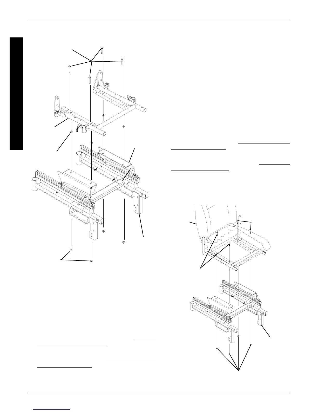
PROCEDURE 6 SEAT/BACK
6. Install footrest assemblies. Refer to PROCEDURE 3 of
the Owner’s Manual, part number 1095602.
Mounting Screws
(Torque to 156-
S
inch pounds)
E
A
T
/
B
A
C
K
Standard
Seat
Spacer
(16-inch Wide
Only)
Seat
Mounting
Plate
5. Remove the four (4) mounting screws and locknuts that
secure the Captain's van seat to the seat mounting plates.
6. Remove captain’s van seat from seat mounting plates.
Installing Captain's Van Seat
1. Position the Captain's van seat on the seat mounting
plates at the position shown in FIGURE 4.
2. Line up mounting holes in the Captain's van seat frame
and the mounting holes in the seat mounting plates.
3. Secure the Captain's van seat to the seat mounting
plates with four (4) mounting screws, and locknuts.
Torque to 156-inch pounds.
4. Plug joystick into controller and secure with new tiewraps.
5. Install battery box(es). Refer to
ING BATTERY BOXES in PROCEDURE 11 of this
manual.
6. Install front and rear shrouds. Refer to
INSTALLING SHROUDS in PROCEDURE 10 of this
manual.
7. Install footrest assemblies. Refer to PROCEDURE 3
of the Owner’s Manual, part number 1095602.
INSTALLING/REMOV-
REMOVING/
Base
Frame
Locknuts
FIGURE 3 - REMOVING/INSTALLING
STANDARD SEAT
REMOVING/INSTALLING
CAPTAIN'S VAN SEAT (FIGURE 4 )
Removing Captain's Van Seat
1. Remove footrest assemblies. Refer to PROCEDURE
3 of the Owner’s Manual, part number 1095602.
2. Remove front and rear shrouds. Refer to
ING/INSTALLING SHROUDS in PROCEDURE 10
of this manual.
3. Remove battery box(es). Refer to
ING BATTERY BOXES in PROCEDURE 11 of this
manual.
4. Unplug joystick from controller.
INSTALLING/REMOV-
REMOV-
Captain's
Van
Seat
Mounting
Screws
(Torque to 156-
inch pounds)
Locknuts
FIGURE 4 - REMOVING/INSTALLING
CAPTAIN'S VAN SEAT
Mounting
Screws
(Torque to 156-
inch pounds)
Seat
Mounting
Plate
Base
Frame
16
SEAT/BACK PROCEDURE 6
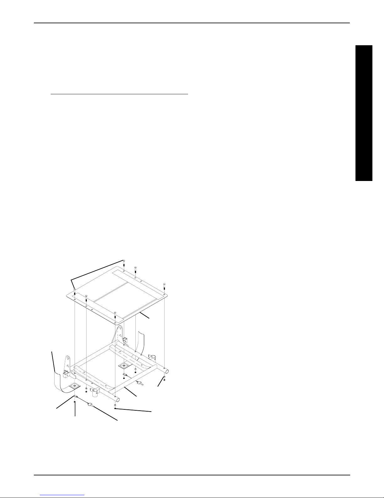
REMOVING/INSTALLING SEAT PAN
(FIGURE 5)
Removing
1. Remove the seat cushion from the seat pan.
2. Remove the flip-back armrests from the wheelchair. Refer
to
INSTALLING/REMOVING FLIP BACK ARMRESTS
in PROCEDURE 4 of the Owner’s Manual, part num-
ber 1095602.
3. Remove the six (6) mounting screws, locknuts, and spacers that secure the seat pan, seat positioning strap, and
quick release pin to the seat frame.
NOTE: When removing seat pan, note tab position of quick
release pin to the seat positioning strap.
Installing
1. Position the NEW seat pan on the seat frame, aligning
the mounting holes of the seat pan and the mounting
holes of the seat frame.
2. Position the seat positioning strap and quick release pin
tab onto the seat frame and secure with mounting screw
and locknut. See FIGURE 9 for proper orientation. Repeat for other seat positioning strap.
NOTE: Check seat positioning strap for proper length. The
width range for the two (2) seat positioning straps are: 16
through 19-inches wide and 20 through 22-inches wide.
Mounting
Screws
Seat
Seat
Positioning
Strap
Pan
3. Reinstall the remaining mounting screws, locknuts, and
spacers. Torque all mounting screws to 75-inch pounds.
4. Remove the protective strips from new seat pan and
reinstall the seat cushion onto the seat pan.
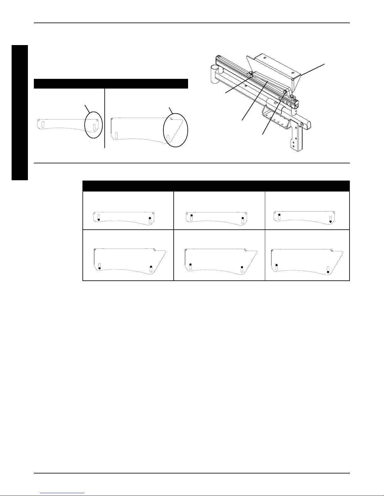
MOUNTING PLATE - SEAT ANGLE
ADJUSTMENT AND INSTALLATION
ORIENTATION (FIGURE 6)
Seat Angle Adjustment
NOTE: The angle of the seat is factory set providing the user
with a 5
either the front or back of the seat mount plate to obtain any
angle between 0
NOTE: There are two (2) heights of seat mounting plates;
low and high. See chart below for proper settings.
1. To obtain a 0o seat dump (DETAIL “A”):
2. To obtain a 10
Installation Orientation
o
seat dump. This angle can be changed by adjusting
o
or 10o seat dump.
A. Loosen the mounting screws that secure the front
and rear of the seat mount plate to the seat support bracket. Repeat for opposite side of wheelchair.
B. Position the mounting screws at the bottom of the
rear slot and the top of the front slot.
C. Securely tighten all four (4) mounting screws. Torque
to 15-in/lbs.
o
seat dump (DETAIL “A”):
A. Loosen the mounting screws that secure the front
and rear of the seat mount plate to the seat support bracket. Repeat for opposite side of wheelchair.
B. Position the mounting screws at the bottom of the
front slot and top of the rear slot.
C. Securely tighten all four (4) mounting screws.
Torque to 15-in/lbs.
S
E
A
T
/
B
A
C
K
Tab
Locknut
FIGURE 5 - REMOVING/INSTALLING SEAT
Quick Release Pin
PAN
Spacer
Seat Frame
Locknut
1. High Seat Mounting Plates: Install with the angled
end toward the rear of the wheelchair.
2. Low Seat Mounting Plates: Install with the thicker
end toward the front of the wheelchair.
17
PROCEDURE 6 SEAT/BACK
DET AIL “A”
S
E
A
T
/
LOW HIGH
Angled End of Seat
Thicker End
Mounting Plate
Rear
Mounting
Screw
B
A
C
K
Seat Support
Bracket
Front
Mounting
Screw
High
Height
Seat
Mount
Plate
SEAT
MOUNT
o
0
SEAT DUMP
o
5
10
o
PLATE
FRONT OF
LOW
CHAIR
HEIGHT
FRONT OF
CHAIR
HIGH
HEIGHT
FIGURE 6 - MOUNTING PLATE - SEAT ANGLE ADJUSTMENT AND INSTALLATION ORIENTATION
REAR OF
CHAIR
REAR OF
CHAIR
FRONT OF
CHAIR
FRONT OF
CHAIR
REAR OF
CHAIR
REAR OF
CHAIR
FRONT OF
CHAIR
FRONT OF
CHAIR
REAR OF
CHAIR
REAR OF
CHAIR
18
 Loading...