

Invacare PHOENIX PLUS Service Manual

PHOENIX PLUS
SERVICE GUIDE
PART NO: 1420254

INTRODUCTION
1) This manual provides basic details to enable the PHOENIX Wheelchair to be
maintained. It is not intended to be a comprehensive maintenance guide/policy, but is
intended for use by competent personnel to enable the chair to adequately maintained.
2) The manual includes detailing assemblies that are maintainable and the relevant
procedures.
3) The Wheelchair is manufactured by:
INVACARE Ltd
South Road
Bridgend Industrial Estate
Bridgend
Mid-Glamorgan
CF31 3PY
SALES TEL NO: 01656 647327 TECHNICAL SERVICE TEL NO: 01656 753337
FAX NO: 01656 649016 FAX NO: 01656 753299
4) For TECHNICAL ADVICE, repairs, servicing, contact Technical Services.
For SPARE PARTS orders contact Sales.
5) Quote the following details at all times:
5.1 Part Number
5.2 Description
5.3 Quantity required
5.4 Serial Number
5.5 Chair Type

POLICY
INVACARE Ltd repair is as follows:
Repairs to ANY component other than those detailed in this manual are not covered. Repairs
to ANY tube metal work is not generally permitted without express permission of INVACARE
Ltd. ALL fasteners i.e. bolts, Nyloc nuts, and any fastener showing damage MUST be
renewed.
In the event of repairing a crash damaged Vehicle we strongly advise you contact INVACARE
TECHNICAL SERVICES DEPARTMENT before proceeding with repairs.
Failure to comply with the above absolves INVACARE Ltd of liability.
Note: Certain components will require removal to carry out maintenance. With the exception
of fasteners, those components should be refitted.

CONTENTS
Page
- Armrests 1
- Upholstery and Back Seat Cloth 2
- Castor Wheel & Fork 3
- Rear Wheel & Tyres 6
- Footrest 8
- Mechanical Brake 9
- Batteries & Charger 10
- Motor Assembly 13
- Gearbox Assembly 15
- Controller with Integral Joystick Remote (DL. 40) 17
- What to do in the event of a fault 18
- Troubleshooting 19
- Diagnostics 19
- Frame & Chassis 22

TOOLS REQUIRED
THE FOLLOWING LIST DETAILS THE BASIC TOOLS REQUIRED TO CARRY OUT THE
MAINTENANCE GIVEN IN THE FOLLOWING CHAPTERS.
2 - Open End Spanner (13mm)
1 - Open End Spanner (11mm)
2 - Open End Spanner (10mm)
1 - Open End Spanner (8mm)
1 - 1/4" BSW Open End Spanner
1 - Combination Spanner (19mm)
1 - Socket / Wrench (Shallow) (19mm)
1 - Phillips Screwdriver (No 1)
1 - Flat Bladed Screwdriver (No 1)
1 - Nylon Mallet
1 - Torque Wrench
1 - Allen Key - (6mm)
1 - Allen Key - (5mm)
1 - Allen Key - (3mm)
1 - Allen Key - (4mm)
1 - Knife
1 - Pressure Gauge
2 - Tyre Levers
1 - Pump
1 - Drift
1 - Vice
1 - Talcum Powder
1 - Valve Remover
1 - Multi-Meter
1 - Soldering Iron
1 - Pin Hammer
1 - Punch
1 - Pair Pliers
1 - Battery Discharge Tester
1 - HHP - Programmer
NOTE: THE ABOVE LIST IS NOT EXHAUSTIVE
1
Phoenix
11/01
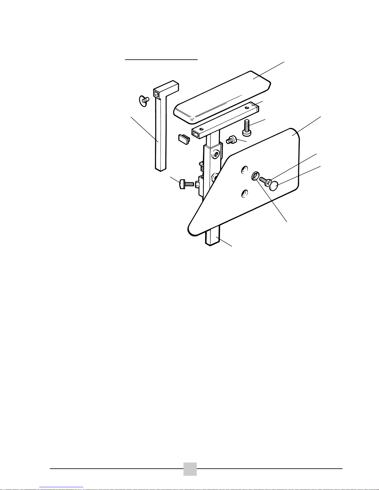
ARM REST
PARTS:
1. Armrest Pad Bracket
2. Hand Knob
3. Armrest Bracket
4. Arm Upright Assembly
5. Washer
6. Cap
7. Screw
8. Skirt Guard
9. Screw (Allen)
10. Armpad Fixing Screws
11. Armrest Pad
Tools Required:
No1 Phillips Screwdriver
Flat Headed Screwdriver
6mm Allen Key
INTRODUCTION
STEP 1
Check that the skirtguard is fixed and not physically damaged. If the panel is loose retighten the fixing screw, install a new panel if necessary.
STEP 2
Check for armpad wear or damage. Replace if necessary.
STEP 3
Check for corrosion or paint damage to the bracketry and replace affected parts where
necessary.
DISMANTLING
STEP 1
Remove the handknob by rotating it anti-clockwise. Pull out the arm assembly.
STEP 2
Remove the two armpad fixing screws under the armpad and remove the armpad.
STEP 3
Remove the allen screw and pull out the armpad bracket.
STEP 4
Carefully remove the 2 caps with a flat headed screwdriver, remove the 2 phillips screws and
remove the skirtguard. Take care not to loosen the washers.
To re-assemble reverse step 4 to 1 taking care not to over tighten the fixing screws as this
could cause burrs and split the plastic washer.
3
10
1
9
8
7
6
5
4
11
2
1
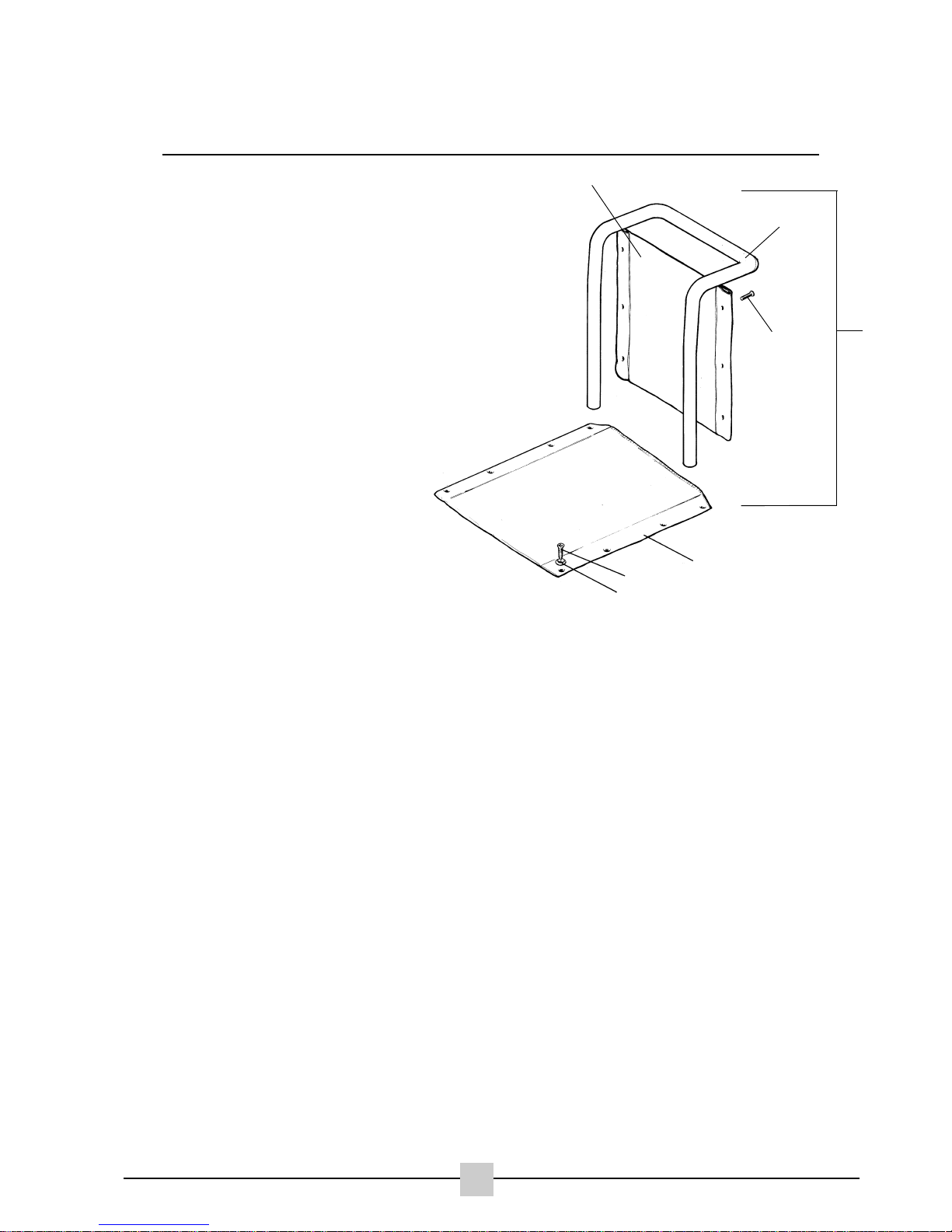
UPHOLSTERY AND BACK/SEAT CLOTH
PARTS:
1. One Piece Backrest Complete
2. One Piece Backpost
3. Taptite Screw
4. Upholstery Washer
5. Seat Upholstery
6. 40cm High Back Upholstery
Tools Required:
No1 Phillips Screwdriver
INTRODUCTION
STEP 1
Check that the upholstery does not sag and is not unevenly stretched, torn or excessively
worn, paying attention to the adjustment features within the tension adjustable back
upholstery.
STEP 2
Check that all stitches are in good condition.
STEP 3
Check that all screws and washers are tight and free of sharp edges and burrs.
DISMANTLING
STEP 1
Remove all fixing screws and detach upholstery from tubework.
To re-assemble reverse above procedure ensuring that the fixing holes in the upholstery and
tubes are properly aligned.
NOTE:
TAKE CARE NOT TO OVER TIGHTEN SCREWS AS THIS MIGHT CAUSE BURRS.
2
Phoenix
11/01
3
2
6
5
3
4
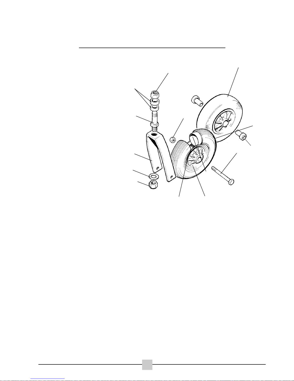
CASTOR WHEEL AND FORK
PARTS:
1. Castor fork
2. Washer
3. Nyloc Nut
4. Axle Bolt
5. Nyloc Nut
6. Pneumatic Castor
7. Bearing
8. Tyre
9. Inner Tube
10. Hub Centre
11. Castor Wheel
12. Fork Stem
13. Bearings
Tools Required:
19mm Socket Spanner x 2
Flat Bladed Screwdriver
Mallet
Pressure Gauge
Tyre Levers
Pump
Drift
INTRODUCTION
STEP 1
Check castor wheels are not buckled or physically damaged. Replace if required.
STEP 2
Check that the wheel bearings run freely without excessive play.
STEP 3
Check that the castor wheel and fork nuts are tight.
STEP 4
Check that the castor forks are bent or damaged.
STEP 5
Check the crown/castor fork bearings for wear and correct adjustment.
STEP 6
Check tyres for wear and correct inflation. Both wheels should show the same degree of wear
(see side of tyre pressure rating). For tyre fitment see rear tyre section.
3
Phoenix
11/01
1
2
3
3
4
5
8
9
10
11
12
13
6
7

CASTOR WHEEL AND FORK
DISMANTLING
STEP 1
Remove castor socket cap with flat bladed screw driver, hold the lower fork stem nut secure
with 19mm spanner and remove the upper fork stem nut.
STEP 2
Gently tap the threaded end to the fork stem with a mallet taking care not to damage the
threads. Remove the castor fork assemblies
STEP 3
Lever out the top fork bearings carefully, using the fork stem as a lever. Take care not to
damage the threads.
STEP 4
Remove the castor fork bearings using a drift and a mallet, tapping gently to avoid damaging
the castor socket and bearing.
STEP 5
To remove the castor wheels undo the axle nut with a 13mm spanner using a second
spanner at the other end of the axle to lock against rotation. Remove the axle bolt and
remove the wheel from the fork.
STEP 6
Remove the bearings by hand.
To reassemble reverse step 6 & 7, but adjust tightness of nut until the wheel runs freely to a
gradual halt.
a) If the wheel stops abruptly, loosen the castor axle nut.
b) If the wheel wobbles (sideplay), tighten the castor axle nut enough to allow free spinning
without sideplay.
TO RE-ASSEMBLE
STEP 1
Insert the fork stem bearings using a mallet and drift across the bearing to prevent damage.
STEP 2
Start at the bottom and place the threaded end of the fork stem through both bearings and in
the castor fork socket.
4
Phoenix
11/01
 Loading...