

Invacare Perfecto 2 SeriesIRC5PO2AW, IRC5PO2VAW Service Manual
Service Manual
0120
Perfecto
Oxygen Concentrator
(HomeFill® Compatible)
™
Series
2
Model IRC5PO2AW
Model IRC5PO2VAW
DEALER: Keep this manual. The procedures in this manual
MUST be performed by a qualified technician.
For more information regarding
Invacare products, parts, and services,
please visit www.invacare.eu.com

WARNING
DO NOT OPERATE THIS EQUIPMENT WITHOUT FIRST READING AND
UNDERSTANDING THIS MANUAL. IF YOU ARE UNABLE TO UNDERSTAND
THE WARNINGS, CAUTIONS, AND INSTRUCTIONS, CONTACT INVACARE
TECHNICAL SERVICES BEFORE ATTEMPTING TO USE THIS EQUIPMENT OTHERWISE SERIOUS INJURY OR PROPERTY DAMAGE MAY RESULT.
WARNING
Invacare products are specifically designed and manufactured for use in conjunction
with Invacare accessories. Accessories designed by other manufacturers have not
been tested by Invacare and are not recommended for use with Invacare products.
PERFECTO2 PARTS COMPATIBILITY
The Platinum concentrator and the Perfecto2 Series concentrator share many
similar components. However, there are some components that are NOT cross
compatible and they are specific to each model.
Parts that can be used for Perfecto2 repairs are listed in the Perfecto2 parts catalog,
form number 08_076. Please reference this catalog before replacing any parts. Use
of incorrect parts could result in injury or property damage.
Perfecto2™
2
Part No 1154245

TABLE OF CONTENTS
TABLE OF CONTENTS
SPECIAL NOTES ................................................................................ 6
FEATURES ........................................................................................ 7
TYPICAL PRODUCT PARAMETERS .................................................... 8
SECTION 1—IMPORTANT SAFEGUARDS .......................................... 10
Important Safeguards...............................................................................................................................10
Radio Frequency Interference ...............................................................................................................11
SECTION 2—INSTALLATION/SEQUENCE OF OPERATION .................. 12
Verification of Battery Free Power Loss Alarm ................................................................................12
Sequence of Operation ...........................................................................................................................12
SensO2 Oxygen Sensor Technology - Ceramic Zirconia Sensor .................................................13
Technical Description .........................................................................................................................13
Operating Sequence ............................................................................................................................13
SECTION 3—PNEUMATIC DIAGRAM ............................................... 15
SECTION 4—TROUBLESHOOTING .................................................... 16
SECTION 5—CABINET .................................................................... 23
Removing Cabinet ....................................................................................................................................23
SECTION 6—PREVENTIVE MAINTENANCE ...................................... 24
Cleaning the Cabinet Filter ....................................................................................................................24
Replacing the Outlet HEPA Filter.........................................................................................................25
Check the Outlet HEPA Filter..........................................................................................................25
Replace the Outlet HEPA Filter .......................................................................................................25
Replacing the Compressor Inlet HEPA Filter ....................................................................................26
Replacing the Muffler Assembly ............................................................................................................26
Cleaning the Heat Exchanger.................................................................................................................29
SECTION 7—COMPRESSOR .............................................................. 31
Replacing Compressor Assembly .........................................................................................................31
Replacing Capacitor .................................................................................................................................33
Rebuilding the Thomas Model 2660 Compressor............................................................................34
Removing Compressor and Compressor Heads .........................................................................35
Rebuilding the Compressor...............................................................................................................38
Rebuilding the GSE Compressor Model 280A
Disassembly...........................................................................................................................................42
Assembly ................................................................................................................................................46
SECTION 8—P.E. VALVE .................................................................. 49
Replacing P.E. Valve..................................................................................................................................49
SECTION 9—SIEVE BEDS ................................................................. 51
Replacing Sieve Beds................................................................................................................................51
SECTION 10—CHECK VALVES ......................................................... 53
Replacing Check Valves...........................................................................................................................53
SECTION 11—REGULATOR .............................................................. 55
Replacing Regulator..................................................................................................................................55
Adjusting Regulator..................................................................................................................................57
..................................................................................42
Part No 1154245
3
Perfecto2™

TABLE OF CONTENTS
TABLE OF CONTENTS
SECTION 12—HEAT EXCHANGER ASSEMBLY .................................. 58
Replacing Heat Exchanger Assembly ...................................................................................................58
SECTION 13—CONTROL PANEL ...................................................... 60
Removing Control Panel.........................................................................................................................60
SECTION 14—COOLING FAN ........................................................... 62
Replacing Cooling Fan .............................................................................................................................62
SECTION 15—P.C. BOARD .............................................................. 65
Replacing P.C. Board................................................................................................................................65
SECTION 16—TRANSFORMER ......................................................... 68
Replacing the Transformer.....................................................................................................................68
SECTION 17—ON/OFF SWITCH ......................................................... 69
Replacing On/Off Switch.........................................................................................................................69
SECTION 18—FLOWMETER .............................................................. 70
Replacing Flowmeter ...............................................................................................................................70
SECTION 19—HOUR METER ............................................................ 71
Replacing Hour Meter.............................................................................................................................71
SECTION 20— 4-WAY VALVE/MANIFOLD ASSEMBLY ........................ 72
Replacing 4-Way Valve and/or Manifold Assembly...........................................................................72
Replacing Pilot Valve Poppets and O-Rings........................................................................................75
SECTION 21—PURITY INDICATORS ................................................ 78
SensO2 Alarm Indicators ........................................................................................................................78
Operation ..............................................................................................................................................78
IRC5PO2AW/IRC5PO2VAW Indicator Lights Explanation......................................................78
SECTION 22—TIMING ..................................................................... 80
Autotuning.............................................................................................................................................80
SECTION 23—LEAK TEST ................................................................ 82
Leak Test ....................................................................................................................................................82
4 Way Valve Function Test....................................................................................................................84
SECTION 24— ALARM TEST ............................................................ 86
Alarm and Sensor Tests..........................................................................................................................86
Power Loss Alarm ...............................................................................................................................86
Low Pressure Test...............................................................................................................................86
Time-Out Test......................................................................................................................................87
High Pressure Test ..............................................................................................................................87
Oxygen Sensor .....................................................................................................................................88
P.E. Valve Coil Test .............................................................................................................................90
Perfecto2™
4
Part No 1154245

SECTION 25— SIEVE BED PRESSURE CHECK ..................................... 91
Checking Sieve Bed Pressure (Model IRC5PO2AW Only)............................................................91
Disassembly...........................................................................................................................................91
Pressure Testing...................................................................................................................................91
Checking Sieve Bed Pressure (Model IRC5PO2VAW Only).........................................................93
Disassembly...........................................................................................................................................93
Installation..............................................................................................................................................93
Pressure Testing...................................................................................................................................94
After Testing .........................................................................................................................................94
CUSTOMER SERVICE AND WARRANTY INFORMATION ................... 95
Part No 1154245
5
Perfecto2™Series

SPECIAL NOTES
SPECIAL NOTES
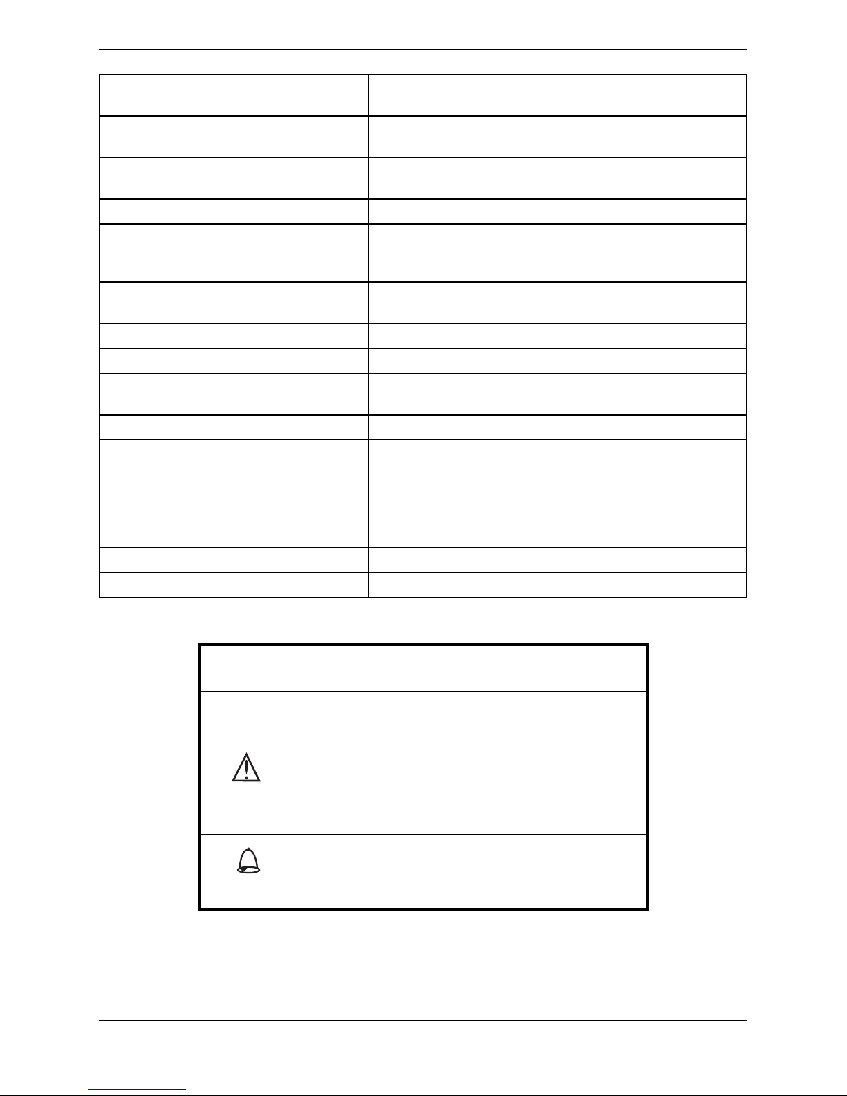
Signal words are used in this manual and apply to hazards or unsafe practices which
could result in personal injury or property damage. Refer to the table below for
definitions of the signal words.
SIGNAL WORD MEANING
DANGER
WARNING
CAUTION
Danger indicates an imminently hazardous situation which,
if not avoided, will result in death or serious injury.
Warning indicates a potentially hazardous situation which, if
not avoided, could result in death or serious injury.
Caution indicates a potentially hazardous situation which, if
not avoided, may result in property damage or minor injury
or both.
NOTICE
THE INFORMATION CONTAINED IN THIS DOCUMENT IS SUBJECT TO
CHANGE WITHOUT NOTICE.
DANGER
DO NOT SMOKE while using this device. Keep all matches, lit cigarettes, candles,
or other sources of ignition out of the room in which this product is located and
away from where oxygen is being delivered.
NO SMOKING signs should be prominently displayed. Textiles and other materials
that normally would not burn are easily ignited and burn with great intensity in oxygen enriched air. Failure to observe this warning can result in severe fire, property
damage and cause physical injury or death.
Perfecto2™
6
Part No 1154245
FEATURES
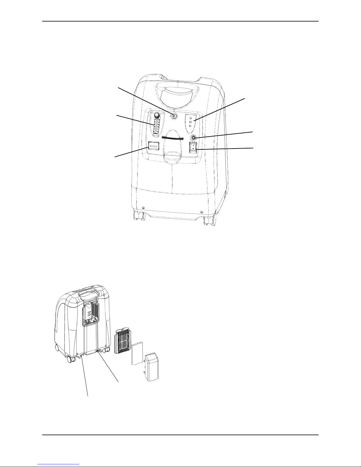
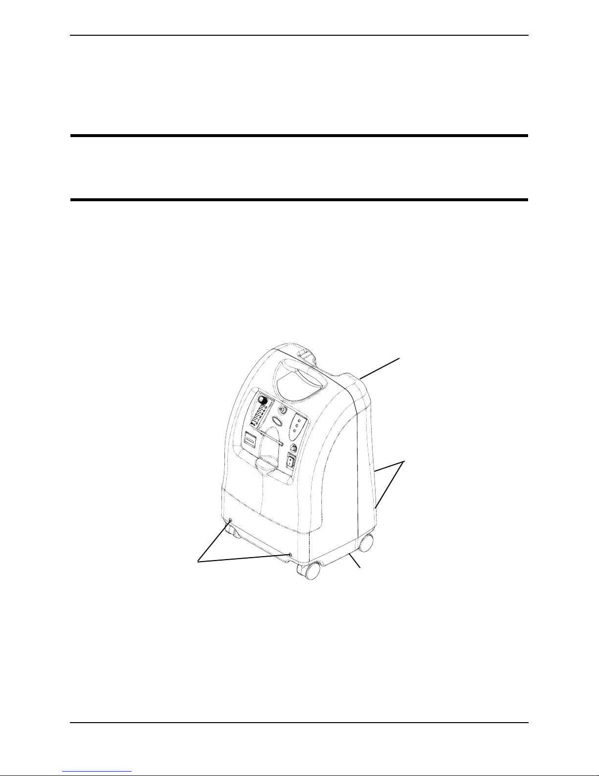
FRONT VIEW
Power Inlet
Outlet Fitting*
Oxygen Outlet
Flowmeter
Oxygen Purity Indicator
Lights / Fault and Power
Indicator Lights (SensO
2
Model Only)
Power Switch
Circuit Breaker
Hour
Meter
ACCESSORIES (NOT SHOWN):
PreciseRX™ Pediatric Flowmeter Accessory - IRCPF16AW
HomeFill home oxygen compressor - IOH200AW
*NOTE: This outlet fitting is to be used only
for filling oxygen cylinders with the HomeFill
home oxygen compressor. The outlet fitting
does not affect concentrator performance.
Refer to the HomeFill owner's manual, part
number 1145804 - Northern, 1145805 Southern, 1145806 - Scandinavian, for
connection and operating instructions. When
not in use, the plug provided with the
concentrator should be inserted into the outlet
fitting. For more information about the
HomeFill, contact your Invacare dealer.
FEATURES
Part No 1154245
7
Perfecto2™

TYPICAL PRODUCT PARAMETERS
TYPICAL PRODUCT PARAMETERS
Electrical Requirements: 230 VAC ± 10% (253 VAC/207 VAC), 50 Hz
Rated Current Input: 1.5 A
Sound Level: 40 dBA max
Altitude: Up to 6,000 ft (1828 m) above sea level without degradation of
concentration levels. Not recommended for use above 6,000 ft
(1828 m).
Atmospheric pressure range: 101.33kPa - 81.22kPa
Oxygen Output
Concentration Levels:
87% to 95.6% @ 0.5 to 5 L/min
93% ± 3% @ 2 L/min
NOTE: Stated concentration levels achieved after initial warm-up
period (approximately 30 minutes).
Maximum Outlet Pressure: 34.5 kPa ± 3.45 kPa. (5 psi ± 0.5 psi)
Flow Range: 0.5 to 5 L/min
For flowrates less than 1 L/min, we recommend the use of the
Invacare Pediatric Flowmeter IRCPF16AW Accessory
Potential Obstruction Alert: 0.5 to 5 L/min
The concentrator detects a condition that may indicate a
potential obstruction of the output oxygen.
Rapid Audible Beeping alert (this alert is deactivated when accessories are connected). May be associated with a flow setting of
0.5 L/min or less.
Power Consumption: Perfecto
Perfecto
AW - 300 W @ 5 L/min, 280 W @ < 3L/min
2
VAW - 320 W @ 5 L/min
2
Pressure Relief Mechanism Operational at: 241 kPa ± 24.1 kPa (35 psi ± 3.5 psi)
Change in maximum recommended flow
0.7 L/min
when back pressure of 7kPa is applied:
Filters: Cabinet, Outlet HEPA and Compressor Inlet
Safety System: Current overload or line surge shutdown. High temperature
Width: 38.1 cm ± 1 cm (15 in. ± 3/8 in)
Height: 58.4 cm ± 1 cm (23 in. ± 3/8 in)
Depth: 30.5 cm ± 1 cm (12 in ± 3/8 in)
Weight: Perfecto
Shipping Weight: Perfecto
Operating Ambient
Conditions:
Exhaust Cooling Air Temperature: Less than Ambient +19°C (+ 45°F)
Perfecto2™
compressor shutdown. High Pressure Alarm w/compressor shutdown. Low Pressure Alarm w/compressor shutdown. Battery
Free Power Loss Alarm. SensO
Oxygen System (SensO2 Model)
2
Potential Obstruction Alert
AW - 20.5 kg ± 1 kg (45 lbs ± 2 lbs)
2
Perfecto
Perfecto
VAW - 18.1 kg ± 1 kg (40 lbs ± 2 lbs)
2
AW - 22.7 kg ± 1 kg (50 lbs ± 2 lbs)
2
VAW - 20.4 kg ± 1 kg (45 lbs ± 2 lbs)
2
10°C - 35°C (50°F - 95°F) at 20-60% relative humidity
8
Part No 1154245
TYPICAL PRODUCT PARAMETERS
O
2
Oxygen Output Temperature:
Cabinet: Impact Resistant flame-retardant plastic cabinet that conforms to
No AP/APG: Not suitable for use in the presence of a flammable anaesthetic
Electrical: No extension cords
Placement: No closer than 30.5 cm (12 in) from any wall, furniture or
Tubing: 2 m (7 ft) cannula with a maximum 15 m (50 ft) of Crush-Proof
Relative Humidity: 20 to 60%
Time of Operation: Up to 24 hours per day
Recommended Storage and Shipping
Temperature:
Environment: Smoke and soot-free. No confined spaces (Example: No closets).
Standards and Regulatory Listing: IEC/EN61000-3-2
Less than Ambient +3°C (+ 8°F)
UL 94-V0
mixture.
draperies to assure sufficient air flow. Avoid deep pile carpets and
heaters, radiators or hot air registers. Floor location only.
Tubing (DO NOT pinch)
-29°C to 65°C (-20°F to 150°F), at 15-95% relative humidity
IEC/EN61000-3-3
IEC/EN 60601-1, A1, A2
IEC/EN 60601-1-2
ISO8359
MDD 93/42/EEC, Annex I and IX
CE marked model: IRC5PO2AW/IRC5PO2VAW
Minimum Operating Time: 30 Minutes
O2 INDICATORS
LABEL
SYMBOL
O2 PURITY INDICATOR LIGHTS
(LED)
SYSTEM OKAY
over 85%
O
2
O
Between 73% to 85% YELLOW Indicator light
2
SYSTEM FAILURE
Below 73%
O
2
GREEN Indicator Light
A. YELLOW Solid
B. YELLOW Flashing Sensor
Failure
Call a qualified technician.
RED Indicator Light
Continuous Audible Alarm
Sieve-GARD Compressor Shutdown.
Part No 1154245
9
Perfecto2™

SECTION 1—IMPORTANT SAFEGUARDS
SECTION 1—IMPORTANT
SAFEGUARDS
Important Safeguards
In order to ensure the safe installation, assembly and operation of the concentrator these
instructions MUST be followed.
WARNING
This section contains important information for the safe operation and use of this
product.
DANGER
Risk of electric shock. DO NOT disassemble. Refer servicing to qualified service
personnel. No user serviceable parts.
TO REDUCE THE RISK OF BURNS, ELECTROCUTION, FIRE OR INJURY TO
PERSONS.
DO NOT place or store product where it can drop into water or other liquid.
DO NOT reach for product that has fallen into water. Unplug IMMEDIATELY.
A spontaneous and violent ignition may occur if oil, grease or greasy substances come
in contact with oxygen under pressure. These substances MUST be kept away from the
oxygen concentrator, tubing and connections, and all other oxygen equipment. DO
NOT use any lubricants unless recommended by Invacare.
Operating Information
For optimum performance, Invacare recommends that each concentrator be on and
running for a minimum of 30 minutes at a time. Shorter periods of operation may reduce
maximum product life.
A product should NEVER be left unattended when plugged in. Make sure the
concentrator is Off when not in use.
DO NOT connect the concentrator in parallel or series with other oxygen concentrators or
oxygen therapy devices.
Keep the oxygen tubing, cord, and unit out from under such items as blankets, bed
coverings, chair cushions, clothing and away from heated or hot surfaces, including space
heaters, stoves and similar electrical appliances.
Perfecto2™
10
Part No 1154245

SECTION 1—IMPORTANT SAFEGUARDS
Radio Frequency Interference
This equipment has been tested and found to comply with EMC limits specified by IEC/
EN 60601-1-2. These limits are designed to provide a reasonable protection against
electromagnetic interference in a typical medical installation.
Other devices may experience interference from even the low levels of electromagnetic
emissions permitted by the above standards. To determine if the emissions from the
concentrator is causing the interference, turn the concentrator Off. If the interference with
the other device(s) stops, then the concentrator is causing the interference. In such rare
cases, interference may be reduced or corrected by one of the following measures:
• Reposition, relocate, or increase the separation between the equipment.
• Connect the equipment into an outlet on a circuit different from that to which the
other device(s) is connected.
Avoid creation of any spark near medical oxygen equipment. This includes sparks from
static electricity created by any type of friction.
Part No 1154245
11
Perfecto2™

SECTION 2—INSTALLATION/SEQUENCE OF OPERATION
I/O
I/
I/
SECTION 2—INSTALLATION/
SEQUENCE OF OPERATION
Verification of Battery Free Power Loss Alarm
Check the concentrator for proper operating conditions.
1. If the unit has been in below-freezing temperatures, allow it to warm up to room
temperature before operating.
2. The concentrator may need to be turned on for four to five seconds to charge the
Battery Free Power Loss Alarm. Connect power cord to outlet and turn the
concentrator on. Turn flow control knob counterclockwise and flow will begin
IMMEDIATELY. Set flow rate to five L/min. Let the unit run for 30 minutes, then turn
unit off.
3. Unplug the power cord and press On/Off ( ) switch to the On ( ) position. An
intermittent audible alarm will sound. This confirms proper operation of the Battery
Free Power Loss Alarm. Turn On/Off switch Off ( ).
4. Connect power cord to outlet and turn on concentrator. Unit will beep on start-up.
5. Check the oxygen concentration per specifications after 30-40 minutes running time.
Sequence of Operation
Turning On ( ) the power switch applies 230 VAC to the compressor motor, hour meter,
transformer, cooling fan and the printed circuit (P.C.) board.
Room air enters the compressor via the cabinet filter and the compressor inlet filter. The
air is compressed by the WOB-L pistons in the compressor to a pressure of 144.79 kPa (21
psi).
As increased pressure creates increased temperature, a heat exchanger is used to lower
the temperature before the air enters the 4-way valve. It is then channeled to a sieve bed
containing the adsorption material. Restriction downstream of the sieve bed causes
pressure to build up inside the sieve bed which is necessary for the adsorption process. A
small amount of relatively pure oxygen enters the top of the second bed through a
restrictive leak in the pressure equalization (P.E.) valve with the balance entering a storage
tank. The nitrogen removed is exhausted back from the bed through the 4-way valve into
room air. A muffler is located at the exhaust end of the valve to muffle the sound of the
exhaust as it exits the concentrator.
The oxygen not being used to exhaust is channeled into the storage tank. The pressurized
oxygen is regulated down to 34.4 kPa (5 psi), enters an accurate flow-measuring device,
flows through Outlet HEPA filter and check valve, then out to the patient.
Perfecto2™
12
Part No 1154245

SECTION 2—INSTALLATION/SEQUENCE OF OPERATION
I/
The electrical activation of the 4-way Valve is accomplished every 8 to 15 seconds by the
pressure sensor and P.C. Board electronics when the pressure reaches a set point of 144.79
kPa (21 psi) output flows 4 L/min and above or 110.32 kPa (16 psi) output flows 3 L/min
and below. The time between cycles is dependent on altitude, flow rate and internal
environmental factors.
A P.E. valve opens just prior to the shift of the 4-way valve. This allows highly
concentrated oxygen to enter the just exhausted bed from the top. This additional
pressure allows the bed to start its cycle at a higher pressure. The P.E. valve will close just
after the shift of the 4-way valve.
If main power is lost, the Battery Free Power Loss Alarm will sound a short "BEEP", with
a long pause after. All units are equipped with a diagnostic alarm system that signals if
the pneumatic pressure or electrical systems malfunction. The troubleshooting guide in
this manual explains the alarm system signals and reasons, in detail. Refer to
Trou bleshooting
on page 16.
SensO2 Oxygen Sensor Technology - Ceramic Zirconia
Sensor
Technical Description
The oxygen being produced by the concentrator flows out of the product tank and into
the flowmeter. A small flow of oxygen produced by the unit is sent through a precision
orifice to the oxygen sensor mounted on the printed circuit board.
As the oxygen enters the sensor, it passes through a screen and contacts the sensing disk.
Electric current flowing through a metal film resistor heats the disk in excess of 300° C.
Oxygen molecules contact the electrode of the disk and pick-up extra electrons to become
oxygen ions. These oxygen ions are attracted to the electrode on the bottom of the zirconia
sensing disk. Because of the crystal structure of the zirconia, only oxygen ions can pass
through. When the oxygen ions reach the bottom electrode, the extra electrons are
released from the oxygen ions and oxygen molecules return to the air. The number of
electrons is directly related to the oxygen concentration. The electrons travel to the P.C.
board where they are counted and the oxygen concentration reading is calculated.
A microprocessor on the P.C. board contains software that interprets the signal being
received from the sensor. It compares the signal to clinically acceptable limits. Signals
outside of the clinically acceptable limits generate responses in the form of lights, audible
indicators, and/or system shut-down.
Operating Sequence
Once the power switch has been turned on ( ), the SensO2 circuit will wait five minutes
for the concentrator to begin producing clinically acceptable oxygen and the oxygen
sensor to stabilize. The GREEN light will illuminate (indicating normal system operation)
while the oxygen sensor is warming up.
Part No 1154245
13
Perfecto2™

SECTION 2—INSTALLATION/SEQUENCE OF OPERATION
After five minutes, if the oxygen purity exceeds 85% ± 2%, the GREEN light will continue
to illuminate.
If the oxygen level is not above 85% ± 2% after the first five minutes, the system will
continue to monitor the O2 and wait for a maximum of 30 minutes from start-up to reach
85% ± 2% before activating an alarm. Environmental factors such as low voltage, high
altitude, or age of the machine will affect the time required to reach 85% ± 2%.
If the oxygen level is not above 85% ± 2% within the first 30 minutes, the oxygen
concentration alarm sequence will activate and the unit will shut down.
When oxygen concentration is above 85% ± 2%, the sensor measures oxygen purity every
10 minutes. If a reading falls below 85% ± 2%, a YELLOW light will illuminate. If the
oxygen purity falls below 73% ± 3% the RED light/Alarm/Shut-Down mode will activate.
Perfecto2™
14
Part No 1154245
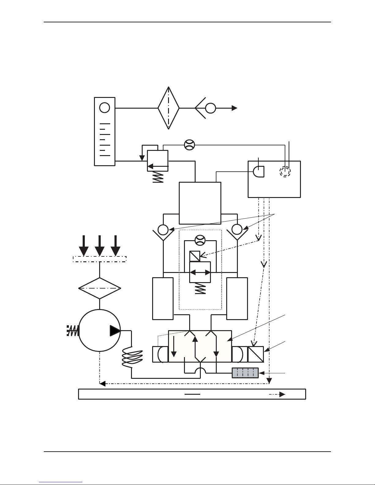
SECTION 3—PNEUMATIC DIAGRAM
Flowmeter
Ouput
HEPA Filter
Output
Check
Valve
Patient
Output
Oxygen Sensor
(SensO
2
models Only)
Pressure Sensor
p.s.i.
O
2
P.C. Board
Pressure
Regulator
Product
Tank
Check
Valves
Air Inlet
Cabinet
Filter
Compressor
Inlet Filter
Sieve
Bed
Sieve
Bed
P.E. Valve
4-way
Valve
Compressor
Relief
Valve
Heat
Solenoid
Pilot
Exhaust
Muffler
LEGEND Pneumatic Connections Electrical Connections
SECTION 3—PNEUMATIC DIAGRAM
Perfecto2 Oxygen Concentrator
Part No 1154245
15
Perfecto2™

SECTION 4—TROUBLESHOOTING
I/
I/O
I/O
SECTION 4—TROUBLESHOOTING
SYMPTOM PROBABLE CAUSE SOLUTION
Normal Operation:
Internal Status Indicators:
RED: Off
GREEN: Off
Unit plugged in, power switch
on. Single beep on start up.
Power loss:
Internal Status Indicators:
RED: Off
GREEN: Off
Unit unplugged, power
switch on, alarm off.
Power loss:
Internal Status Indicators:
RED: Off
GREEN: Off
Unit plugged in, power switch
, alarm off, battery Free
circuit drained.
No Problems. System Okay.
No Problems. Battery Free Circuit drained. Plug in cord
()
and turn power switch ON
recharge.
No power at outlet. Check electrical outlet with a table lamp
or voltmeter set on VAC scale. If outlet
isn't working, check protective device in
home's electrical panel or consult an
electrician. Also ensure that unit is
properly plugged in. DO NOT use
extension cords. Move to another outlet
or circuit.
Power cord:
a. Frayed.
b. Broken or damaged spade.
c. Spade connector from power
cord loose or disconnected
(inside back of unit).
()
On/Off
a. Disconnected wire.
b. Faulty switch.
Circuit breaker tripped. Reset breaker.
switch.
a. Reattach cord.
b. Replace power cord connectors on
plug.
c. Reattach connector.
Check all electrical connections to the
()
ON/OFF
disconnected wires.
If the concentrator does not come on at all
and wiring is intact, color code and
remove wires one at a time. Remove and
replace with new one. Transfer wires from
old switch to new switch one at a time to
the matching contact.
NOTE: Breaker may trip to safeguard
concentrator during a power surge.
If breaker trips IMMEDIATELY, there is a
probable short in the unit. Check for
pinched or charred wires. If the breaker
does not trip, run unit for approximately
two hours. The circuit breaker should be
less than 10 ohms. If breaker trips again,
there is an internal problem. Contact
Invacare Technical Service.
switch for any
to
Perfecto2™
16
Part No 1154245

SYMPTOM PROBABLE CAUSE SOLUTION
Power Loss:
(Continued)
Internal Status Indicators:
RED: Off
GREEN: Off
Unit plugged in, power
switch, alarm off. Battery
Free circuit drained.
Internal Power
Loss Senso
Internal Status Indicators:
RED: Off
GREEN: Off
Alarm may or may not be on.
Control Panel Indicators:
RED: Off
YELLOW: Off
GREEN: Off
Fan operates, Compressor
not operating.
High Pressure:
Internal Status Indicators:
RED: One Flash
GREEN: Two Flashes
Unit plugged in, power switch
on, continuous alarm.
Compressor shut down.
:
2
SECTION 4—TROUBLESHOOTING
P.C. board.
a. P.C. board damaged.
b. Loose or damaged connector.
Transformer assembly.
a. Faulty.
b. Connector loose or
disconnected.
c. Faulty wiring.
P.C. board faulty. Replace P.C. board. Unit requires retiming
P.C. board:
a. Malfunction
b. Disconnected wire.
c. Shifting valve at pressures greater
than 25 p.s.i. for Perfecto
.
2
4-way Valve:
a. Not shifting.
b. Bad coil.
c. Coil resistance.
a. Replace P.C. Board. Refer to
Replacing P.C. Board
on page 65.
b. Repair or replace connector.
a. Replace. Refer to Replacing the
Transformer on page 68.
b. Reattach connector.
c. Replace transformer assembly. Refer
to Replacing the Transformer
on
page 68.
after P.C. board replacement. Refer to
Replacing P.C. Board
on page 65.
a. Set flow to max L/min. for
concentrator. Check voltage across
Pilot Valve 1 on volt DC scale. If
meter reads 0 volts when unit is
turned on, replace P.C. board
b. Check spade connectors on pilot
valves 1 or 2 and connectors on P.C.
board.
c. Replace P.C. board. Unit requires
retiming after P.C. board
replacement. Refer to Replacing P.C.
Board on page 65.
a. Check voltage. If voltage rises to
approximately 24 volts D.C. when
unit shuts down, P.C. board is
functioning properly. Replace the
valve if shorted or open. Refer to
Replacing 4-Way Valve and/or
Manifold Assembly on page 72.
b. Replace 4-way valve. Refer to
Replacing 4-Way Valve and/or
Manifold Assembly on page 72.
c. Coil should read 175 ohms ± 20.
Part No 1154245
17
Perfecto2™

SECTION 4—TROUBLESHOOTING
SYMPTOM PROBABLE CAUSE SOLUTION
LOW PRESSURE:
Internal Status Indicators:
RED: One Flash
GREEN: One Flash
Or
RED: One Flash
GREEN: Three Flashes
Control Panel Indicators:
RED: On
YELLOW: Off
GREEN: Off
Unit plugged in, power switch
on, continuous audible alarm.
Compressor shut down
(Failure to cycle due to low
pressure).
Defective Parts:
Internal Status Indicators:
RED: One Flash GREEN: Five
Flashes
Or
RED: Two Flashes
GREEN: Three Flashes
Control Panel Indicators:
RED: On
YELLOW: Off
GREEN: Off
Unit plugged in, power switch
on, continuous audible alarm.
Compressor shut down.
Compressor inlet filter dirty or
plugged.
Compressor:
a. Leaks at fittings or tubing
b. Leaking or defective relief valve.
c. Insufficient voltage at outlet.
d. Worn cup seals or gaskets.
Heat exchanger:
a. Leak at tubing or body chamber.
b. Inspect tubing and heat
exchanger.
Regulator cracked or leaking. Replace regulator. Refer to Replacing
P.E. valve leaking. Replace P.E. Valve. Check voltage at P.E.
Defective main valve coil. a. Replace main valve.
Connector loose. Reattach connector.
Defective P.E. valve coil. (Resistance
80 ohms ± 10.)
Defective P.E. valve. Replace P.E. valve. Refer to Replacing P.E.
Connector loose. Reattach connector.
Defective P.C. board. Replace P.C. board. Refer to Replacing
Replace compressor inlet filter. Refer to
Replacing the Compressor Inlet HEPA
Filter on page 26.
a. Replace or repair.
b. Repair leak or replace.
c. DO NOT use extension cords. Use
another outlet.
d. Rebuild top end of compressor. Refer
to Rebuilding the Thomas Model
2660 Compressor on page 34.
a. Replace or retighten.
b. Replace or retighten tubing. Replace
heat exchanger. Refer to Replacing
Heat Exchanger Assembly on
page 58.
Regulator on page 55.
valve connector on 24 volt D.C. scale. The
P.E. Valve activates or energizes
approximately one second prior to the
activation of the 4 way valve with
approximately 24 volts. If voltage is in
excess of 24 volts consistently, replace the
P.C. board. Refer to Replacing P.C. Board
on page 65. If the P.C. board voltage acts
normally, replace the P.E. valve. Refer to
Replacing P.E. Valve
Note: Check for leaks starting at the
compressor output through all the
pneumatic connections. Major leaks will
cause system pressures to remain below
adequate shift (exhaust) pressures and will
cause compressor shutdown.
b. Replace main valve coil.
Replace P.E. coil if shorted or open on
resistance check. Refer to Replacing P.E.
Valve on page 49.
Valve on page 49.
P.C. Board on page 65.
on page 49.
Perfecto2™
18
Part No 1154245

SYMPTOM PROBABLE CAUSE SOLUTION
Unit not operating: Alarm:
On or Off
Internal Status Indicators:
RED: Two Flashes
GREEN: Four Flashes Or
RED: Two Flashes GREEN:
Five Flashes
Low Concentration: NOTE:
Check for O
calibrated Oxygen Analyzer
at Test Point 1 (oxygen
outlet) of the concentrator.
Internal Status Indicators:
RED: Two Flashes
GREEN: One Flash73%
Shutdown Control Panel
Indicators: SensO
RED: On
YELLOW: Off
GREEN: Off
For SensO
indicator will signal extremely
low purity and will be
accompanied by a continuous
audible alarm and a system
shutdown. Repairs are
required.
purity using a
2
ONLY:
2
2
units, the RED
SECTION 4—TROUBLESHOOTING
P.C. board Failure. Replace P.C. board.Refer to Replacing P.C.
Board on page 65.
Cabinet filters dirty. Clean or replace. Refer to Cleaning the
Cabinet Filter on page 24, Replacing the
Outlet HEPA Filter on page 25, and
Replacing the Compressor Inlet HEPA
Filter on page 26.
Compressor inlet filter dirty. Replace inlet filter. Refer to Replacing the
Compressor Inlet HEPA Filter on page 26.
Compressor:
a. Defective.
b. Faulty capacitor.
c. Bad motor windings.
d. Worn seals.
e. Bad bearings.
f. Leak at fittings or tubing.
g. Leaky or defective relief valve.
h. Insufficient voltage (outlet).
Heat exchanger:
a. Leak at tubing or body chamber.
b. Inspect tubing and heat
exchanger.
Regulator cracked or leaking. Replace. Refer to Replacing Regulator
Exhaust muffler dirty or plugged. Replace. Refer to Replacing the Muffler
Fan:
a. Not operating. Unit overheating.
b. Faulty fan.
Sieve beds defective. Replace. Refer to Checking Sieve Bed
Tubing kinked or blocked. Repair or replace.
P.C. board:
a. Shifts at wrong pressures.
a. Replace compressor. Refer to
Replacing Compressor Assembly
on
page 31.
b. Replace capacitor. Refer to Replacing
Capacitor on page 33.
c. Replace compressor.
d. Rebuild top end of compressor. Refer
to Rebuilding the Thomas Model
2660 Compressor on page 34.
e. Replace compressor.
f. Replace fittings or tubing.
g. Replace relief valve.
h. DO NOT use extension cords.
a. Replace or retighten.
b. Replace or retighten tubing. Replace
heat exchanger. Refer to Replacing
Heat Exchanger Assembly on
page 58.
on
page 55.
Assembly on page 26.
a. Leads to fan disconnected.
Reconnect.
b. Replace.Refer to Replacing Cooling
Fan on page 62.
Pressure (Model IRC5PO2AW Only) on
page 91 or Checking Sieve Bed Pressure
(Model IRC5PO2VAW Only) on page 93.
Check pressure at product tank. Pressure
should rise to 144.79 kPa (21 p.s.i.) at shift
point. If not, replace P.C. Board. Refer to
Replacing P.C. Board
on page 65.
Part No 1154245
19
Perfecto2™

SECTION 4—TROUBLESHOOTING
SYMPTOM PROBABLE CAUSE SOLUTION
Low Concentration
(Continued)
Fluctuating Flow: Regulator/Flowmeter:
Unit Excessively Loud: Pneumatic exhaust:
Flowmeter:
a. Flowmeter opened beyond
maximum flow rate.
b. Cracked or broken fitting.
c. Input tubing leaking or loose.
Timing. To accommodate for varying tolerances
P.E. valve:
a. Bad coil.
b. Restrictor blockage.
Inspect P.C. board restrictor tubing
for kinks or tears.
a. Incorrectly set regulator.
b. Flowmeter malfunction.
Outlet HEPA filter:
a. Dirty or plugged a. If low flow conditions persist, replace
a. Muffler cracked, damaged or
missing.
b. Muffler tubing disconnected or
damaged.
Compressor inlet filter missing and/or
orange sticker removed.
Compressor removed. a. Replace Compressor. Refer to
Incorrect style of inlet filter
(aftermarket).
a. Return flow to maximum setting.
b. Replace fitting.
c. Repair or replace. Refer to Replacing
Flowmeter on page 70.
when replacing components, an adjustable
timer is used to control the shifting of the
Pressure Equalization (P.E.) valve. Refer to
on page 80.
Timing
a. Replace P.E. valve.
b. Replace P.E. valve. Refer to Replacing
P.E. Valve on page 49.
Replace P.C. board. Unit may need
retiming after board replacement. Refer to
Replacing P.C. Board
a. Check pressure at oxygen outlet.
Adjust regulator.
b. If flow is still unstable, check for leaks
starting at the compressor outlet
fitting through all pneumatic
connections. If no leaks are found
and flow is still fluctuating, replace
the regulator. If pressure at test point
is within spec (5 p.s.i. ± 0.5 max.
[34.4 kPa ± 6.89]), replace
flowmeter. Refer to Replacing
Flowmeter on page 70.
outlet HEPA filter. Refer to Replacing
the Outlet HEPA Filter on page 25.
a. Replace. Refer to Replacing the
Muffler Assembly on page 26.
b. Reconnect or replace tubing.
a. Replace compressor inlet filter. Refer
to Replacing the Compressor Inlet
HEPA Filter on page 26.
Replacing Compressor Assembly
page 31.
a. Replace with factory OEM sound
reduced style inlet HEPA filter.
on page 65.
on
Perfecto2™
20
Part No 1154245

SYMPTOM PROBABLE CAUSE SOLUTION
Unit Overheats: Base exhaust vent plugged or
restricted.
Cabinet filters dirty or blocked. Clean or replace. Refer to Cleaning the
Fan:
a. Leads to fan disconnected.
b. Defective fan.
c. Fan installed upside down.
Heat exchanger:
a. Dirty or plugged.
b. Damaged.
Compressor:
a. Defective.
b. Faulty capacitor.
c. Bad motor windings.
d. Worn seals.
e. Bad bearings.
Line voltage excessive (surge). Have line voltage inspected by certified
Oxygen Purity:
Good
Internal Status Indicators:
Control Panel Indicators:
RED: Off
YELLOW: On
GREEN: On
After 30 minutes of
run time, unit operates
normally, oxygen purity
within normal range.
GREEN or YELLOW panel
indicator should illuminate.
P.C. board defective. Replace P.C. board. Refer to Replacing
SECTION 4—TROUBLESHOOTING
Place unit at least 30,5 cm (12-inches)
from any wall. DO NOT place unit on
pile or shag carpeting that may restrict
air flow.
Cabinet Filter on page 24.
a. Reconnect leads.
b. Replace fan. Refer to Rebuilding the
Thomas Model 2660 Compressor on
page 34.
c. Install fan with air flow arrow pointing
down.
a. Clean heat exchanger.
b. Replace heat exchanger. Refer to
Replacing Heat Exchanger Assembly
on page 58.
a. Replace compressor. Refer to
Replacing Compressor Assembly
page 31.
b. Replace capacitor. Refer to Replacing
Capacitor on page 33.
c. Replace compressor.
d. Replace compressor.
e. Replace compressor.
electrician. A voltage regulator may be
required and is obtainable from your local
electric company.
P.C. Board on page 65. Unit may need
retiming after P.C. board replacement.
Refer to Timing
on page 80.
on
Part No 1154245
21
Perfecto2™

SECTION 4—TROUBLESHOOTING
SYMPTOM PROBABLE CAUSE SOLUTION
Unit Not Operating,
Internal Status Indicators:
RED: Off
GREEN: Off
Control Panel Indicators:
RED: Off
YELLOW: Off
GREEN: Off
Power Switch ON.
Continuous audible alarm.
Unit Operating,
Internal Status Indicators:
RED: Three Flashes
GREEN: One Flash
Control Panel Indicators:
RED: Off
YELLOW: Flashing
GREEN: On
Potential Obstruction Alert
does not activate on flows
less than 0.5 L/min.
Transformer assembly:
a. Assembly connector
disconnected.
b. Faulty transformer assembly.
Internal repairs required. Replace SensO
System leak. Repair leak in product tank, regulator,
Defective check valves. Replace check valves. Refer to Replacing
a. Reattach connector.
b. Replace transformer assembly. Refer
to Replacing the Transformer
on
page 68.
circuit board. Refer to
2
Replacing P.C. Board
on page 65.
tubing, fittings, or flow meter.
Check Valves on page 53.
Perfecto2™
22
Part No 1154245
SECTION 5—CABINET
Cabinet Assembly
Mounting
Screws
Base Assembly
Mounting
Screws
SECTION 5—CABINET
Removing Cabinet
DANGER
To prevent electrical shock, ALWAYS disconnect concentrator from electrical outlet
before servicing.
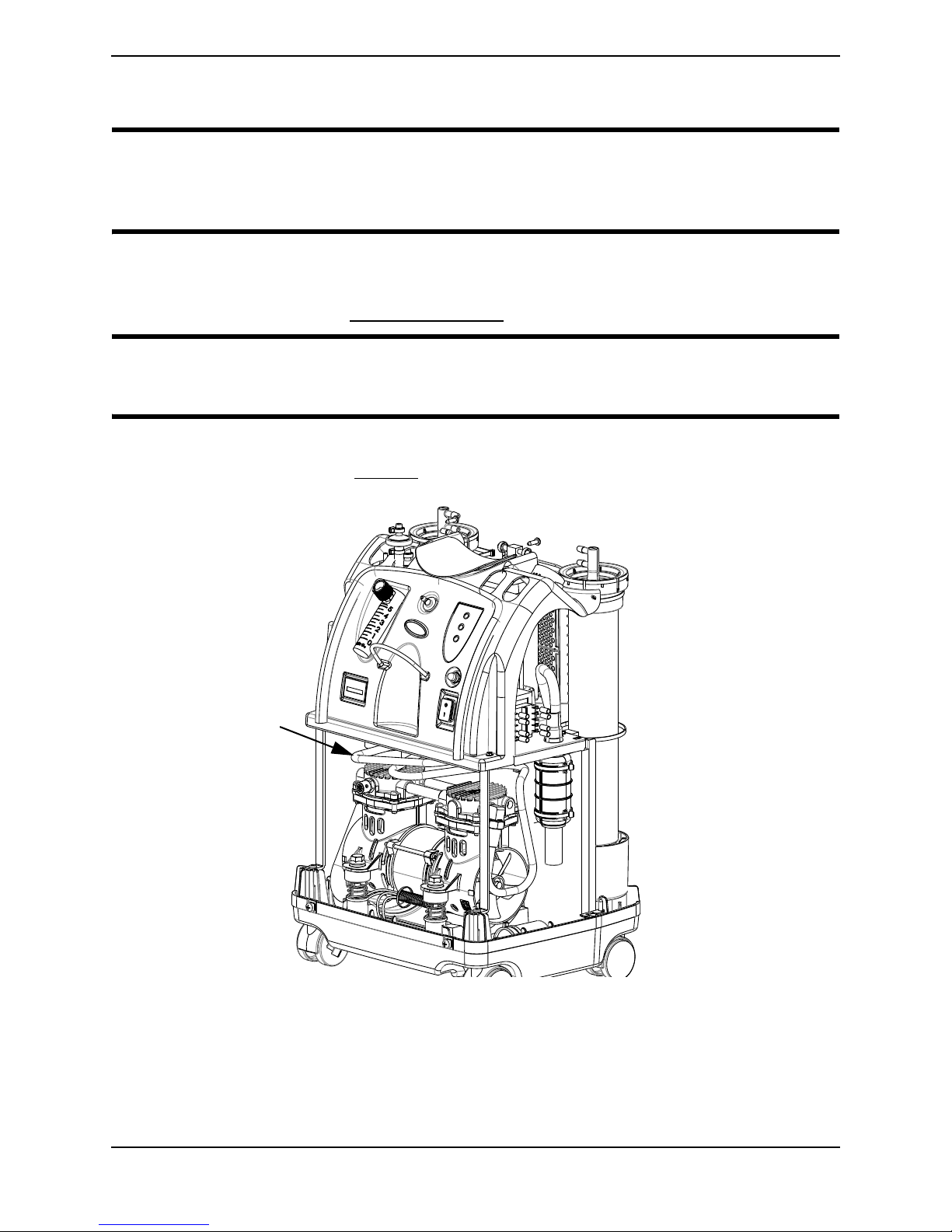
NOTE: For this procedure, refer to FIGURE 5.1.
1. Unplug unit.
2. Remove the four mounting screws that secure cabinet assembly to the base assembly.
3. Lift the cabinet straight up.
NOTE: When required, vacuum inside of the cabinet and exposed foam insulation.
4. To re-install cabinet, reverse STEPS 2-3.
L
Part No 1154245
FIGURE 5.1 Removing Cabinet
23
Perfecto2™

SECTION 6—PREVENTIVE MAINTENANCE
SECTION 6—PREVENTIVE
MAINTENANCE
DANGER
To prevent electrical shock, ALWAYS disconnect concentrator from electrical outlet
before servicing.
WARNING
The Invacare concentrators are specifically designed to minimize routine preventive
maintenance. Only qualified personnel should perform preventive maintenance on
the concentrator.
NOTE: At a minimum, preventive maintenance MUST be performed according to the
maintenance record guidelines. In places with high dust or soot levels, maintenance may need to
be performed more often. Refer to Troubleshooting on page 16 for plugged filter symptoms and to
Preventive Maintenance Record on page 30.
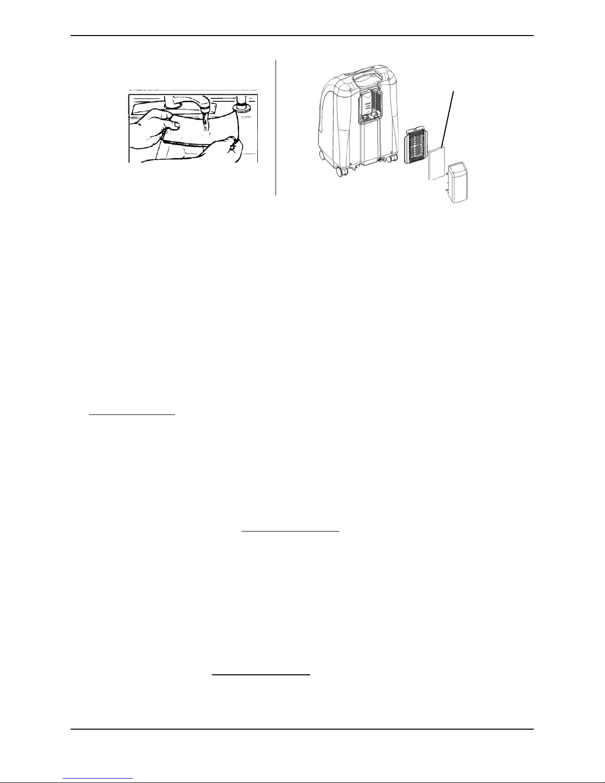
Cleaning the Cabinet Filter
NOTE: For this procedure, refer to FIGURE 6.1 on page 25.
NOTE: There is one cabinet filter located on the back of the cabinet.
1. Remove the filter and clean as needed.
NOTE: Environmental conditions that may require more frequent inspection and cleaning of the
filter include but are not limited to: high dust, air pollutants etc.
2. Clean the cabinet filter with a vacuum cleaner or wash in warm soapy water and rinse
thoroughly.
3. Dry the filter thoroughly before reinstallation.
CAUTION
DO NOT operate the concentrator without the filter installed.
Perfecto2™
24
Part No 1154245
SECTION 6—PREVENTIVE MAINTENANCE
Filter
FIGURE 6.1 Cleaning the Cabinet Filter
Replacing the Outlet HEPA Filter
Check the Outlet HEPA Filter
NOTE: The outlet HEPA filter can be checked during preventive maintenance or between patients
by performing the following procedure.
1. Turn the concentrator on and adjust the flowmeter to the maximum flow of the unit.
2. Observe the flowmeter's flow indicator while connecting a 15.24 m (50 ft) cannula tube
to the outlet barb of the concentrator (not shown).
3. If the flow indicator fluctuates, the outlet HEPA filter may need replacement. Refer to
Troubleshooting on page 16.
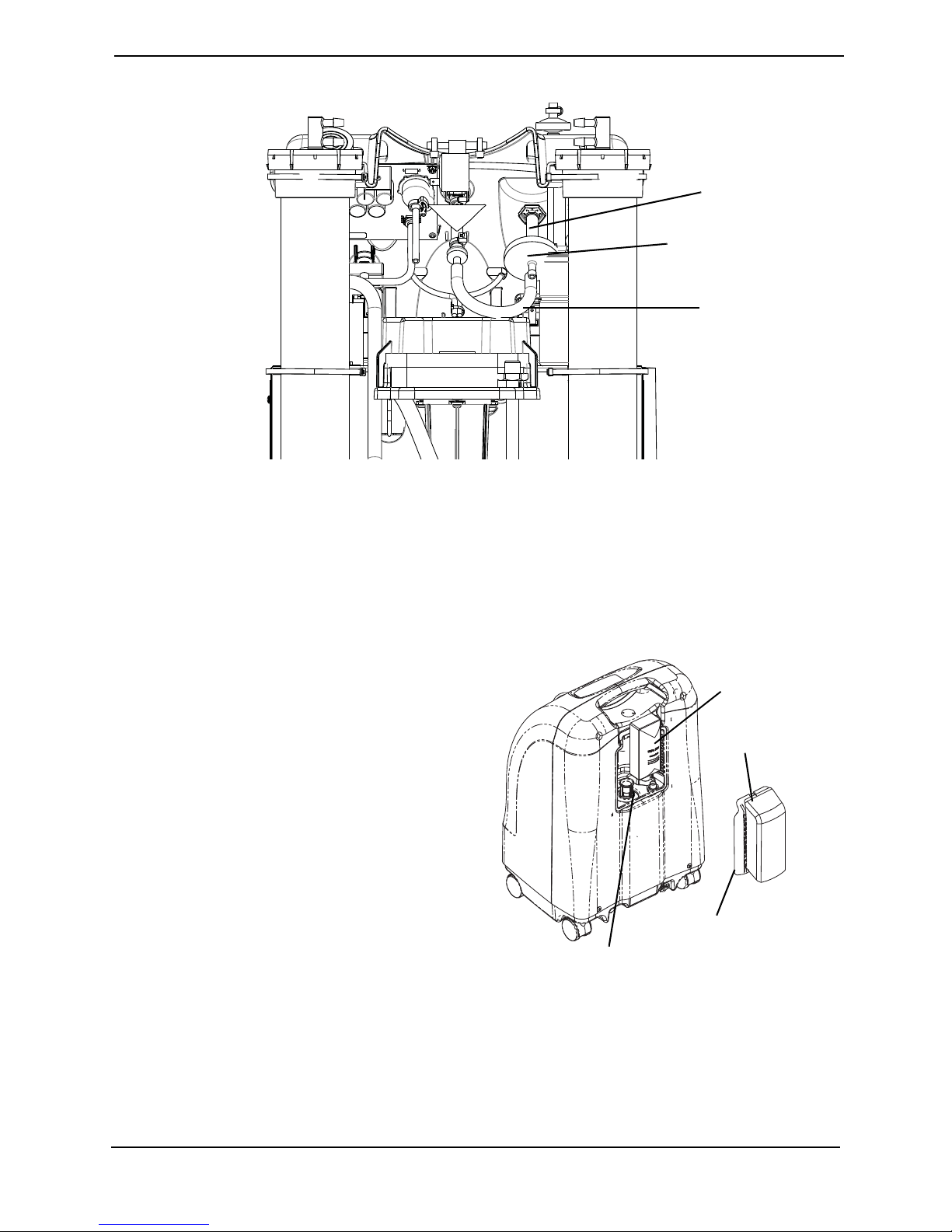
Replace the Outlet HEPA Filter
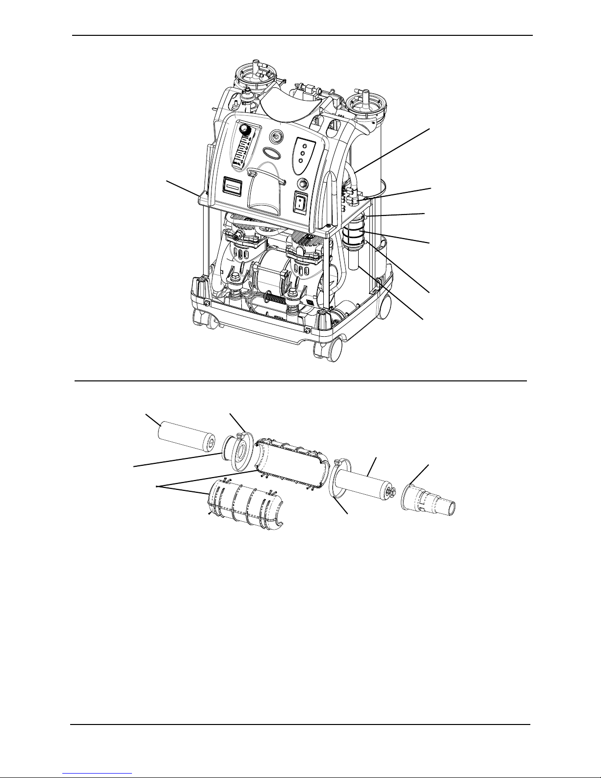
NOTE: For this procedure, refer to FIGURE 6.2.
NOTE: Perform this procedure during preventive maintenance or between patients depending on
the outlet HEPA filter check results.
1. Unplug the unit.
2. Remove the cabinet. Refer to Removing Cabinet
3. For easier access to the outlet HEPA filter, remove the compressor inlet HEPA filter by
grasping the compressor inlet filter, pull outward and up until filter is dislodged from
rubber base (FIGURE 6.3).
4. With a flat head screwdriver, remove the tubing from both sides of the existing outlet
HEPA filter by prying the tubing away from the outlet HEPA filter.
on page 23
5. Discard existing outlet HEPA filter.
6. Connect tubing to both sides of the new outlet HEPA filter as shown below.
7. Install cabinet. Refer to Removing Cabinet on page 23.
Part No 1154245
25
Perfecto2™
SECTION 6—PREVENTIVE MAINTENANCE
Tubing
Outlet HEPA Filter
Tubing
Filter Access Panel with Air
Scoop
Center
Tab
Compressor Inlet
HEPA Filter
Rubber Base
FIGURE 6.2 Replace the Outlet HEPA Filter
Replacing the Compressor Inlet HEPA Filter
NOTE: For this procedure, refer to FIGURE 6.3 on page 26.
NOTE: Perform this procedure as needed depending upon the environment the concentrator is
used in.
1. Unplug the unit.
2. Remove the filter access panel with air
scoop by pressing down on center tab
and pulling panel out.
3. Grasp the compressor inlet HEPA filter,
pull outward and up until filter is
dislodged from rubber base.
4. Discard the existing compressor inlet
HEPA filter.
5. Install new compressor inlet filter by
inserting the filter into the rubber base.
6. Push the filter down until the rubber
base touches the edge of the filter.
7. Reinstall the filter access panel.
FIGURE 6.3 Replacing the Compressor
Inlet HEPA Filter
Replacing the Muffler Assembly
NOTE: For this procedure, refer to FIGURE 6.4 on page 27 and FIGURE 6.5 on page 28.
Perfecto2™
26
Part No 1154245
SECTION 6—PREVENTIVE MAINTENANCE
Tie-Wrap
Top of Manifold
Exhaust Tube
Bottom of Manifold Exhaust
Tube
“F” Tube
Rubber
Grommet
NOTE: Perform this procedure as needed depending upon the environment the concentrator is
used in.
1. Unplug unit.
2. Remove cabinet. Refer to Removing Cabinet on page 23.
3. Cut tie wrap that secures the bottom of the manifold exhaust tube to the “F” tube.
4. Remove the bottom of the manifold exhaust tube from the “F” tube.
5. Disconnect and remove the top of the manifold exhaust tube from the grommet.
FIGURE 6.4 Replacing the Muffler Assembly
6. Push the muffler assembly down through the opening in the sound box.
7. Cut the two tie wraps around the muffler assembly.
8. Separate the muffler assembly (Detail “A” in FIGURE 6.5).
9. Inspect the components to ensure they are clear.
10. Do one of the following:
• Replace exhaust canister and throttling muffler if plugged or restricted.
• Install only new throttling muffler if exhaust canister is in good condition.
11. Install new/existing muffler assembly by reversing STEPS 2-10.
12. Reinstall cabinet. Refer to Removing Cabinet
Part No 1154245
on page 23.
27
Perfecto2™
SECTION 6—PREVENTIVE MAINTENANCE
Exhaust Canister
Throttling Muffler
Sound Box
Top of Manifold
Exhaust Tube
Tie Wraps
Rubber Grommet
DETAIL “A”
Muffler
Grommet
Throttling
Muffler
Assembly
8” Tie-Wrap
Exhaust
Canister
8” Tie-Wrap
Exhaust
Muffler
Grommet
Muffler Body
Tie Wraps
FIGURE 6.5 Replacing the Muffler Assembly
Perfecto2™
28
Part No 1154245
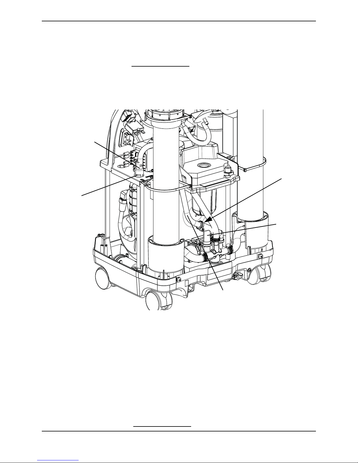
SECTION 6—PREVENTIVE MAINTENANCE
Heat Exchanger
Cleaning the Heat Exchanger
DANGER
To prevent electrical shock, ALWAYS disconnect concentrator from electrical outlet
before servicing.
NOTE: For this procedure, refer to FIGURE 6.6 on page 29.
1. Unplug unit.
2. Remove cabinet. Refer to Removing Cabinet on page 23.
CAUTION
Use care not to deform heat exchanger when installing, removing or cleaning.
3. Remove excess dirt using compressed air or vacuum.
4. Reinstall cabinet. Refer to Cabinet on page 23.
FIGURE 6.6 Cleaning the Heat Exchanger
Part No 1154245
29
Perfecto2™
 Loading...