

Invacare MyOn HC Service Manual
Invacare® MyOn™ HC
SERVICE MANUAL
( M A I N T E N A N C E A N D A D J U S T M E N T )
The procedures in this manual MUST be performed by a qualified technician.
MyOn HC July 2015

TABLE OF CONTENTS
T A B L E OF C O N T E N T S
SECTION 1—TROUBLESHOOTING A N D MAI N T E N AN CE ........................................4
Troubleshooting .................................................................................................................4
Maintenance Guidelines & Safety Inspection ....................................................................4
Tightened Torques .............................................................................................................7
Suggested Maintenance Procedures ................................................................................7
Stability Warning ................................................................................................................8
SECTION 2—FRONT HANGERS ...........................................................................................9
Adjusting Footrest Height ..................................................................................................9
Replacing Heel Strap .........................................................................................................10
Installing Calf Strap ...........................................................................................................10
Installing Angle Adjustable Footplate ...............................................................................11
Adjusting the Leg rest Angle ..............................................................................................11
Adjusting the Footplate Height ..........................................................................................11
Adjusting Calf pad Height ..................................................................................................12
Adjusting Calf pad Depth ..................................................................................................12
SECTION 3—ARMRESTS ......................................................................................................13
Removing/Installing Removable Armrest (n°1) ................................................................13
Adjusting Removable Armrest Height .................................................................................. 13
Removing/Installing Swing Away Armrest (n°3) .................................................................... 14
Replacing Armrest Arm Pad ................................................................................................ 15
SECTION 4—SEAT/BACK ........................................................................................................ 16
Removing Back Canes ........................................................................................................ 16
Removing/Installing Seat Upholstery ................................................................................... 16
Removing/Installing Standard Back Upholstery ................................................................... 17
Contour (Adjustable) Back Upholstery ................................................................................. 18
Installing/Replacing Contour (Adjustable) Back Upholstery ................................................. 19
Adjusting the Height Adjustable Back .................................................................................. 20
Adjusting the Back Angle backrest ...................................................................................... 20
Removing/Installing different type of backrests .................................................................... 21
Removing/Installing/Adjusting the Back Cane Bracket ......................................................... 22
Installing/Removing Seat Posture Belt ................................................................................. 23
Installing/Removing the Back Brace .................................................................................... 24
MyOn HC 2

TABLE OF CONTENTS
SECTION 5—REAR WHEELS/FRONT CASTERS ................................................................... 25
Removing/Installing Rear Wheels ........................................................................................ 25
Fixed Axles .......................................................................................................................... 25
Quick-Release Axles ........................................................................................................... 26
Adjusting Quick-Release Axles ............................................................................................ 27
Replacing Handrims ............................................................................................................ 27
Adjusting the Wheelbase Length ......................................................................................... 28
Adjusting Rear Wheel Height ............................................................................................... 29
Replacing/Repairing Rear Wheel Tire/Tube ........................................................................ 30
Replacing/Repairing Front Caster Tire/Tube ....................................................................... 30
Adjusting Forks .................................................................................................................... 31
Removing/Installing/Repositioning the Caster Assemblies ................................................... 32
Adjusting Caster Angle ........................................................................................................ 32
Adjusting Caster Assembly Position .................................................................................... 33
SECTION 6—SEAT-TO-FLOOR HEIGHT……………………………………………………34
Seat Angle ......................................................................................................................... .34
Measuring Seat-to-Floor Height ........................................................................................ .35
Changing Seat-to-Floor Height ......................................................................................... .35
SECTION 7—WHEEL LOCKS .......................................................................................... .37
Adjusting Wheel Locks ...................................................................................................... .37
Replacing Wheel Lock Handle .......................................................................................... .38
Installing/Adjusting Hub Brakes ........................................................................................ .39
SECTION 8—OPTIONS ................................................................................................ .41
Installing/Adjusting Dual Handrim (DHR) ......................................................................... .41
SECTION 9—ANTI-TIPPERS ..................................................................................... .42
Installing/Adjusting Swing Away Anti-Tippers .................................................................. .42
Installing/Adjusting Tipper Aid ........................................................................................... .43
3 MyOn HC
SECTION 1—MAINTENANCE GUIDELINES
SEC TIO N 1 —TR OUB L ES HOOT ING
A N D M A I N T EN A N CE GU IDE LIN ES
NOTE: Once a year, take your wheelchair to a qualified dealer for a thorough inspection
and servicing. Regular cleaning will reveal loose or worn parts and enhance the smooth
operation of your wheelchair. To operate properly and safely, your wheelchair must be
cared for just like any other vehicle. Routine maintenance will extend the life and
efficiency of your wheelchair. Initially and at least every twelve months, follow these
maintenance procedures:
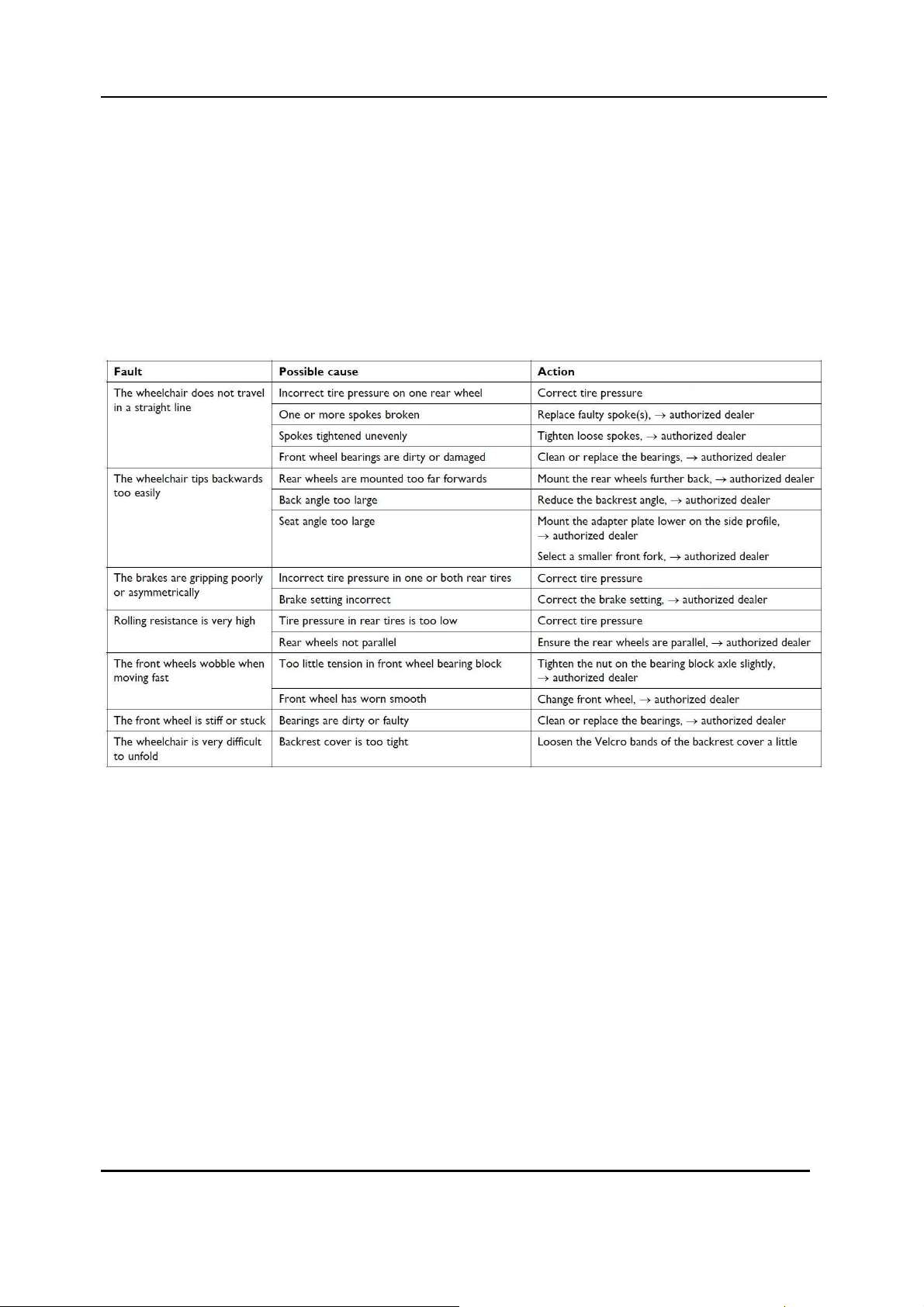
Trouble shooting
Maintenance guide lines:
Safety Inspection Checklists
Initial adjustments should be made to suit the personal body structure needs and
preferences of the user. Thereafter follow these maintenance procedures:
Inspect/Adjust initially (User or Attendant)
Wheelchair rolls straight (no excessive drag or pull to one side).
Ensure all hardware is tight properly (see page 7). Adjustment/replacement →
authorized dealer.
All fasteners on clothing guards are secure.
Arms are secure but easy to release and locking systems engage properly.
Adjustable height arms operate and lock securely.
Armrest arm pad sits flush against arm tube.
Seat and/or back upholstery have no rips.
Ensure seat upholstery is adjust properly (see page 16) to obtain a perfect locking of the
folding mechanism. Adjustment/replacement
MyOn HC 4
→ authorized dealer.

SECTION 1— MAINTENANCE GUIDELINES
Inspect adjustable angle back attaching hardware is securely tightened.
Adjustment/replacement
Ensure hand grips are secure to backrest canes.
Sealed bearings and axle nut tension are correct.
No excessive side movement or binding when rear wheels are lifted and spun.
→ authori
zed dealer.
Inspect/Adjust initially (User or Attendant)
Quick-release axles lock properly (see page 29).
Inspect handrims for signs of rough edges or peeling finish.
Inspect for broken spokes. Adjustment/replacement
Wheel/fork assembly has proper tension when caster is spun. Caster should come to
a gradual stop.
Wheel bearings are clean and free of moisture.
Loosen/tighten locknut if wheel wobbles noticeably or binds to a stop. Adjustment/replacement →
authorized dealer.
Ensure all caster/wheel/fork/head tube fasteners are secure (see pages 7 & 34).
Wheel locks do not interfere with tires when rolling.
→ authori
zed dealer.
Wheel lock pivot point are free of wear and looseness.
Wheel locks are easy to engage.
Inspect tires/casters for flat spots and wear.
Check pneumatic tires for proper inflation (recommended tire pressure is listed on
the sidewall of the tire).
Clean quick-release axles with a Teflon® lubricant.
Ensure axles are free from dirt, lint, etc.
Ensure roller bearings are free from dirt, lint, etc.
Adjust wheel locks as tires wear. Adjustment/replacement → authorized dealer.
Clean and wax all parts.
Clean upholstery and armrests.
Ensure casters are free of debris.
Inspect/Adjust Weekly (User or Attendant)
Wheelchair rolls straight (no excessive drag or pull to one side).
Quick-release axles lock properly (see page 29).
Inspect for broken spokes. Adjustment/replacement → authorized dealer.
Wheel/fork assembly has proper tension when castor is spun. Castor should come to a gradual stop.
Inspect tires/casters for flat spots and wear.
Check pneumatic tires for proper inflation (recommended tire pressure is listed on the side wall of the
tire).
Ensure casters are free of debris.
5 MyOn HC

SECTION 1—MAINTENANCE GUIDELINES
Inspect/Adjust Monthly (User or Attendant)
Inspect seat positioning strap for any signs of wear. Ensure buckle latches. Verify hardware that
attaches strap to frame is secure and undamaged. Adjustment/replacement → authorized dealer.
Loosen/tighten locknut if wheel wobbles noticeably or binds to a stop. Adjustment/replacement →
authorized dealer.
Wheel bearings are clean and free of moisture.
Wheel locks do not interfere with tires when rolling.
Wheel lock pivot point are free of wear and looseness.
Ensure all caster/wheel/fork/head tube fasteners are secure (see pages 7 & 34).
Ensure all hardware is tight properly (see page 7). Adjustment/replacement →
authorized dealer.
Ensure hand grips are secure to backrest canes.
Ensure casters are free of debris.
Ensure seat upholstery is adjust properly (see page 16) to obtain a perfect locking of the
folding mechanism. Adjustment/replacement → authorized dealer.
Inspect/Adjust every twelve months (Repairer or Dealer)
Wheelchair rolls straight (no excessive drag or pull to one side).
Arms are secure but easy to release and locking systems engage properly.
Adjustable height arms operate and lock securely.
Armrest arm pad sits flush against arm tube.
All fasteners on clothing guards are secure.
Seat and/or back upholstery have no rips.
Inspect the backrest attaching hardware and mechanisms are securely tightened.
No excessive side movement or binding when rear wheels are lifted and spun.
Inspect handrims for signs of rough edges or peeling finish.
Inspect side frame and folding mechanism for signs of cracks, flaked paint or deformed metal work.
Inspect tires/casters for flat spots and wear.
Check pneumatic tires for proper inflation (recommended tire pressure is listed on
the sidewall of the tire).
Wheel lock pivot point are free of wear and looseness.
Clean upholstery and armrests.
Sealed bearings and axle nut tension are correct.
Wheel/fork assembly has proper tension when caster is spun. Caster should come to
a gradual stop.
Loosen/tighten locknut if wheel wobbles noticeably or binds to a stop.
Wheel bearings are clean and free of moisture.
Wheel locks are easy to engage.
Clean quick-release axles with a Teflon lubricant.
Ensure axles are free from dirt, lint, etc.
Ensure roller bearings are free from dirt, lint, etc.
Adjust wheel brakes as tires wear.
Clean and wax all parts.
Ensure casters are free of debris.
MyOn HC 6
Thread
Tightening torque
SECTION 1— MAINTENANCE GUIDELINES
C A U T I O N
It is compulsary to use original Invacare spare parts which you can obtain from any
Invacare authorized dealer. A list of spare parts is available at www.invacare.eu.com
W A R N I N G
After ANY adjustments, repair or service and before use, make sure all attaching
hardware is tightened securely - otherwise injury or damage may occur.
C A U T I O N
DO NOT over tighten hardware attaching to the frame. This could cause damage to
the frame tubing.
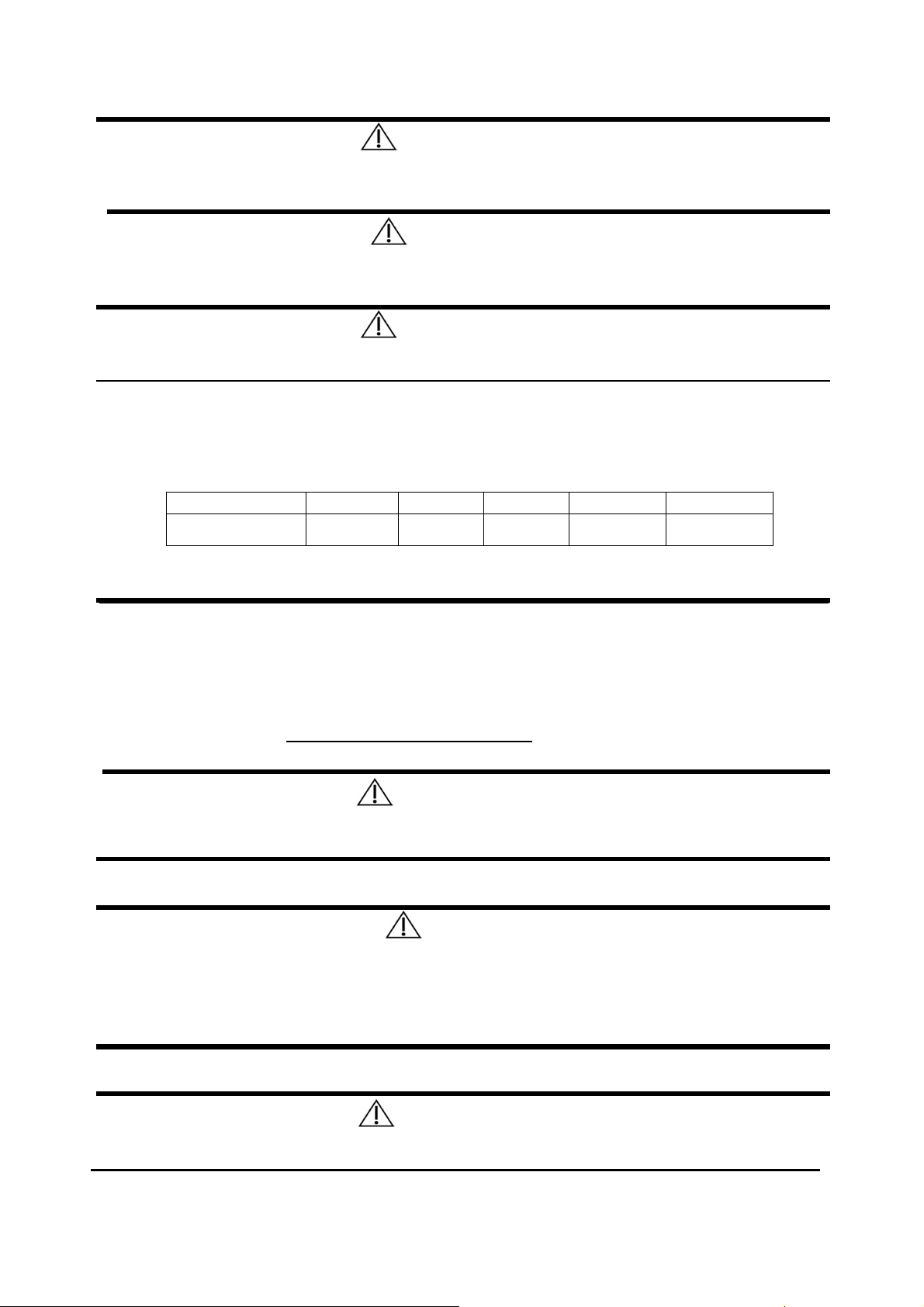
Tightening torques
The tightening torques stated in the following table are dependent on the thread diameters for
the nuts and bolts for which no special values are determined. All values apply to dry and
grease-free threads.
M4
in Nm mini/max
1,5/3 Nm 3/6 Nm 7/12 Nm 10/20 Nm 20/30 Nm
Caution: All other nuts not noted here must be tightened FINGERTIGHT!
M5 M6 M8 M10/12
Suggested Maintenance Procedures
1. Before using your wheelchair, make sure all nuts and bolts are tight. Check all parts
for damage or wear and replace. Check all parts for proper adjustment.
2. Keep quick release axles free of dirt and lint to ensure positive locking and proper
operation. Refer to Adjusting Quick Release Axles on section 5.
W A R N I N G
DO NOT use WD-40, 3-in- 1 oil, or other penetrating lubricants on quick-release
axles. Otherwise, binding and/or damage to the wheelchair may occur.
3. Clean quick release axles once a week with a Teflon lubricant.
DO NOT use your wheelchair unless it has the proper tire pressure (BAR, KPa or P.S.I.).
DO NOT over inflate the tires. Failure to follow these suggestions may cause the
tire to explode and cause bodily harm. The recommended tire pressure is on the
sidewall of the tire.
4. Recommended tire pressure is listed on the sidewall of the tire (BAR, KPa or P.S.I.).
W A R N I N G
As with any vehicle, the wheels and tires should be checked periodically for cracks
and wear, and should be replaced if damaged.
7 MyOn HC
C A U T I O N
SECTION 1— MAINTENANCE GUIDELINES & STABILITY WARNING
5. The wheels, castors and tires should be checked periodically for cracks and wear, and
should be replaced when necessary.
6. Regularly check for loose spokes in the rear wheels. If loose, have them adjusted.
7. Periodically check handrims to ensure they are secured to the rear wheels. Refer to
Replacing Handrims on section 5.
8. Periodically check caster wheel bearings to make sure they are clean and free from
moisture. Use a Teflon® lubricant if necessary.
9. Check upholstery for sagging, rips or tears.
10. Clean upholstery with mild soap and water.
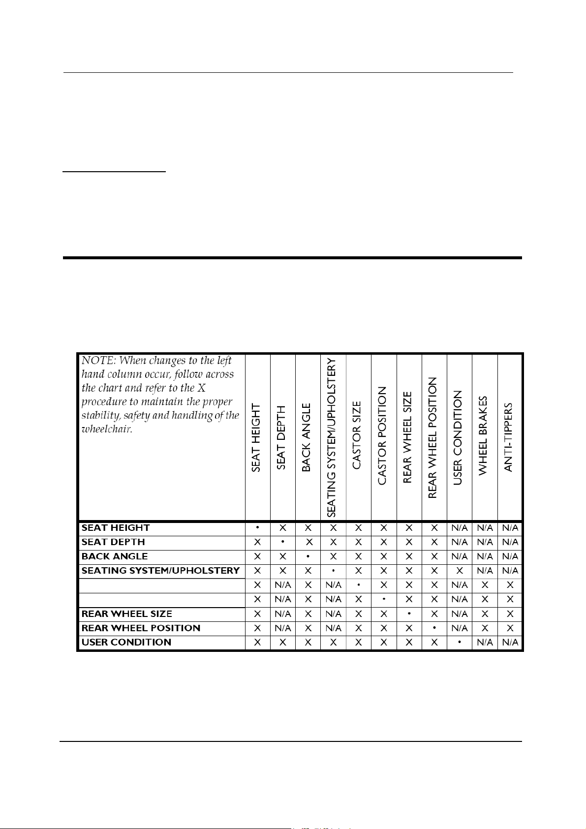
Stability Warning
The seat height, seat depth, back angle, seating system/upholstery, size/position of the
rear wheels, size/position of the front casters, seating options (e.g. back bag, …) as well
as the user condition directly relate to the stability of the wheelchair. Any change to one or
any combination of the nine may cause the wheelchair to increase/decrease in stability.
CASTER SIZE
Seat-to-floor heights have specific positions depending on rear wheel size, rear wheel
position, front caster size/position and seat-to-floor angle.
These adjustments MUST be performed by a qualified technician.
Refer to sections 5 & 6.
MyOn HC 8
5
0 m
m mini
SECTION 2—FRONT HANGERS
SECTION 2—FRONT HANGERS
W A R N I N G
After ANY adjustments, repair or service and before use, make sure all
attaching hardware is tightened securely - otherwise injury or damage
may occur.
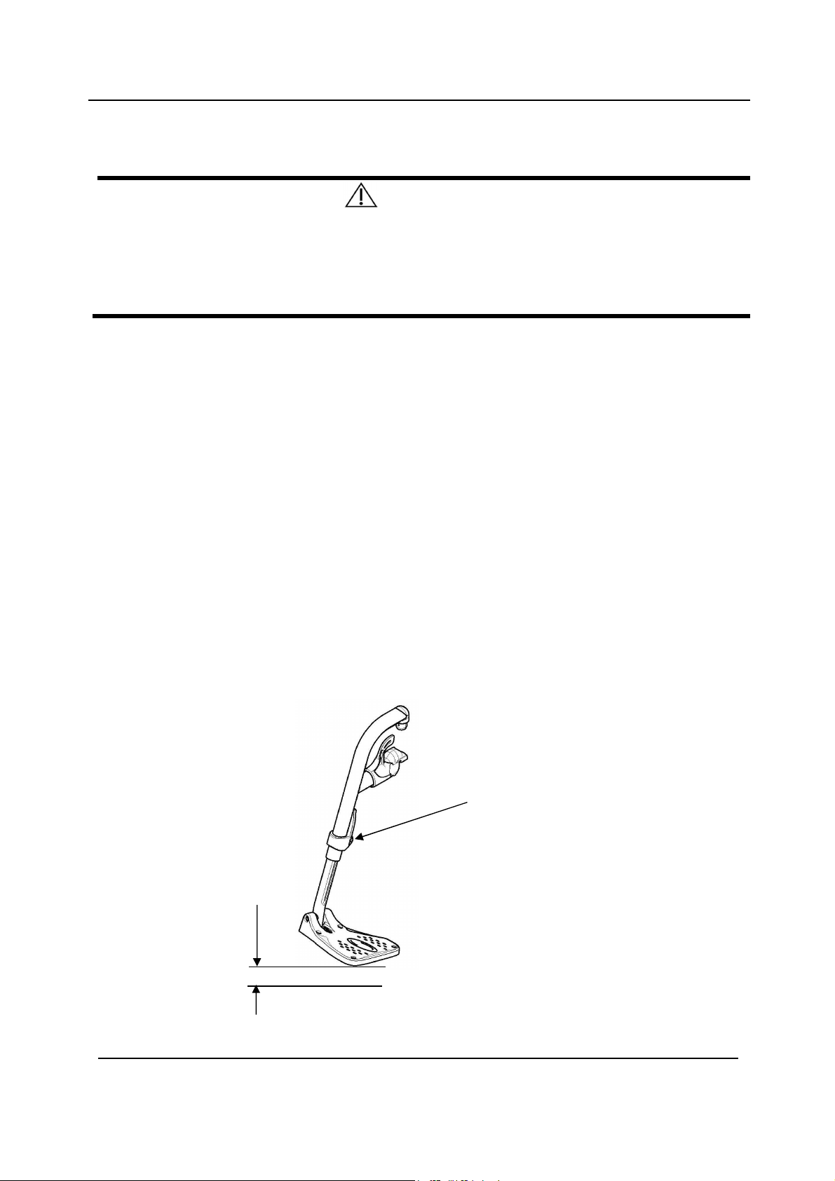
A 50 mm clearance between the bottom of the footplate and the ground/floor
MUST be maintained at all times.
Adjusting Footrest Height
NOTE: For this procedure, refer to FIGURE 2.1.
1. Remove calf strap, if so equipped.
2. Unscrew locking screw (M6).
3. Position the footrest assembly to the desired height.
NOTE: A 50 mm clearance between the bottom of the footplate and the ground/floor
MUST be maintained at all times.
4. If the distance between the bottom of footplate and the ground/floor is not 50 mm
minimum, adjust footrest tube accordingly.
5. Using the locking screw (M6), secure the footrest tube to the footrest support.
Securely tighten.
6. If necessary, repeat STEPS 2-5 to adjust remaining footrest.
7. Reinstall the calf strap, if so equipped.
Locking
screw (M6)
FIGURE 2.1 Adjusting Footrest Height
9 MyOn HC
SECTION 2—FRONT HANGERS
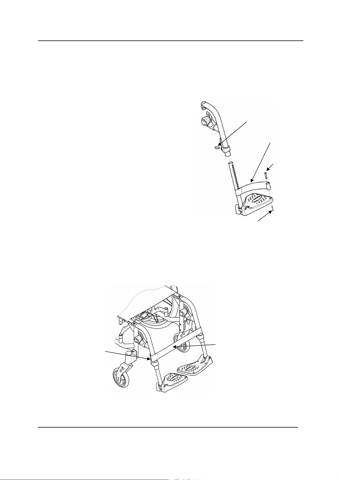
Replacing Heel Strap
NOTE: For this procedure, refer to FIGURE 2.2.
1. Remove the locking screw (M6) that secure the footrest tube to the footrest
support.
2. Remove the lower footrest assembly.
3. Remove the mounting screw, strap pin
that secure the heel strap to the
footplate.
4. Slide heel strap over footrest tube.
Locking screw (M6)
NOTE: When securing the heel strap to
the footrest assembly, tighten the
mounting screw and strap pin until they
are secure.
5. Using the mounting screw, strap pin,
secure the heel strap to the footplate.
6. Using the locking screw (M6), secure
the footrest tube to the footrest
support.
FIGURE 2.2 Replacing Heel Strap
Installing Calf Strap
NOTE: For this procedure, refer to FIGURE 2.3.
1. Secure the optional calf strap around the hanger hook.
Heel strap
Strap pin
Mounting screw
Hanger
hook
Calf strap
FIGURE 2.3 Installing Calf Strap
MyOn HC 10
f
ootplate
SECTION 2—FRONT HANGERS
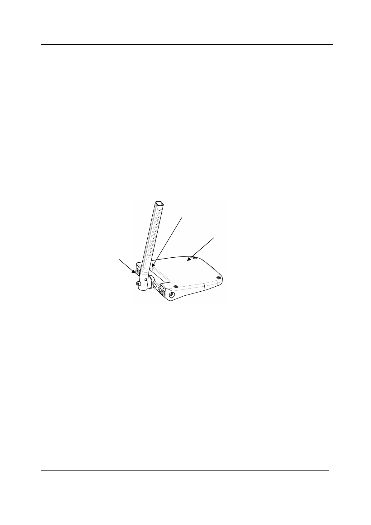
Installing Angle Adjustable Footplate
NOTE: For this procedure, refer to FIGURE 2.4.
NOTE: This procedure is for individual Angle Adjustable Footrests only.
1. Position the angle adjustable footplate on the footrest support tube at the desired
height.
2. Using the locking screw (M6), loosely secure the angle adjustable footplate to the
footrest support tube.
NOTE: Refer to Adjusting Footrest Height paragraph on page 9.
3. Using the mounting screw, adjust to the desired angle (Tooth plates) by rotating the
footplate and depth by sliding the footplate into the tooth plates support.
4. Using the mounting screw (M6), secure the Angle Adjustable Footplate to the
footrest tube. Securely tighten.
5. If necessary, repeat STEPS 1-4 to adjust remaining Angle Adjustable Footplate.
Tooth plates
Angle adjustable
Mounting
screw (M6)
FIGURE 2.4 Installing Angle Adjustable Footplate
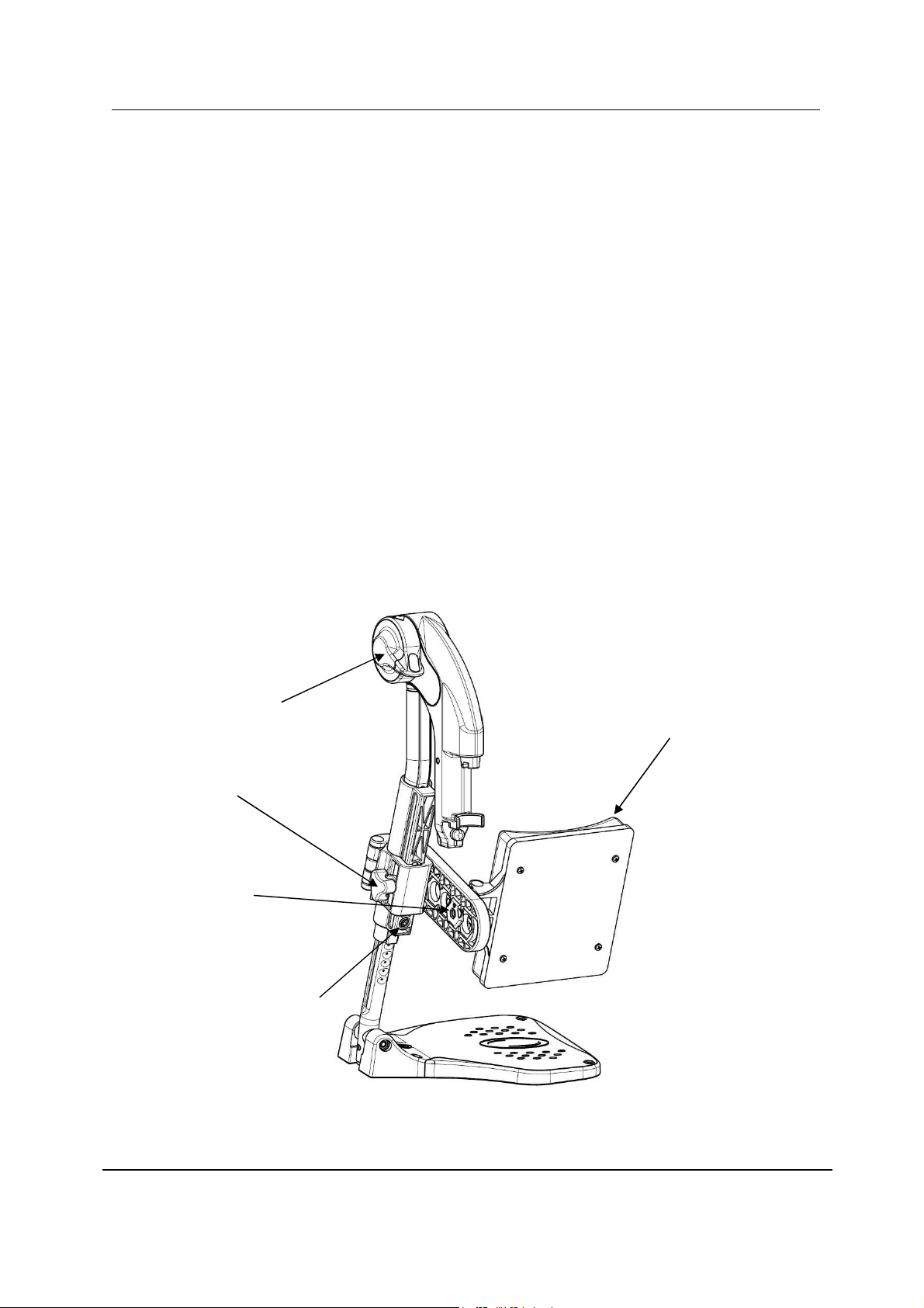
Adjusting Elevating Leg rest Angle, Height and Calf
pad Height/Depth
NOTE: For this procedure, refer to FIGURE 2.5.
Adjusting the Leg rest Angle
1. Rotate the indexer lever with one hand while supporting the leg rest with your other
hand.
2. When a suitable angle is obtained, let go off the knob and the leg rest will lock into the
desired position.
3. If necessary, repeat STEPS 1-2 to adjust remaining elevating leg rest angle.
Adjusting the Footplate Height
1. Loosen locking screw (M6) securing the slide tube to the elevating leg rest.
11 MyOn HC
SECTION 2—FRONT HANGERS
2. Reposition footplate to desired height, securely tighten locking screw (M6).
3. If necessary, repeat STEPS 1-2 to adjust remaining footplate height.
Adjusting Calf pad Height
1. Loosen the locking button that secure the calf pad bracket to the elevating leg rest
assembly.
2. Slide the calf pad bracket up or down until the desired calf pad height is obtained.
3. Tighten the locking button securing the calf pad bracket to the elevating leg rest
assembly.
4. If necessary, repeat STEPS 1-3 to adjust remaining calf pad bracket.
Adjusting Calf pad Depth
1. Remove the mounting set that secure the calf pad to the calf pad bracket.
2. Insert mounting set through one of four calf pad bracket mounting holes.
3. Using the mounting set (M5) secure the calf pad to the calf pad bracket.
4. If necessary, repeat STEPS 1-3 to adjust remaining calf pad assembly.
Indexer lever
Calf pad
Locking
button
Mounting
set (M5)
Locking screw (M6)
FIGURE 2.5 Adjusting Elevating Leg rest Height and Calf pad Height/Depth
MyOn HC 12
SECTION 3—ARMRESTS
screw
(M5)
SE C T I ON 3 — A RMRE S TS
W A R N IN G
After ANY adjustments, repair or service and BEFORE use, make sure all attaching
hardware is tightened securely - otherwise injury or damage may occur.
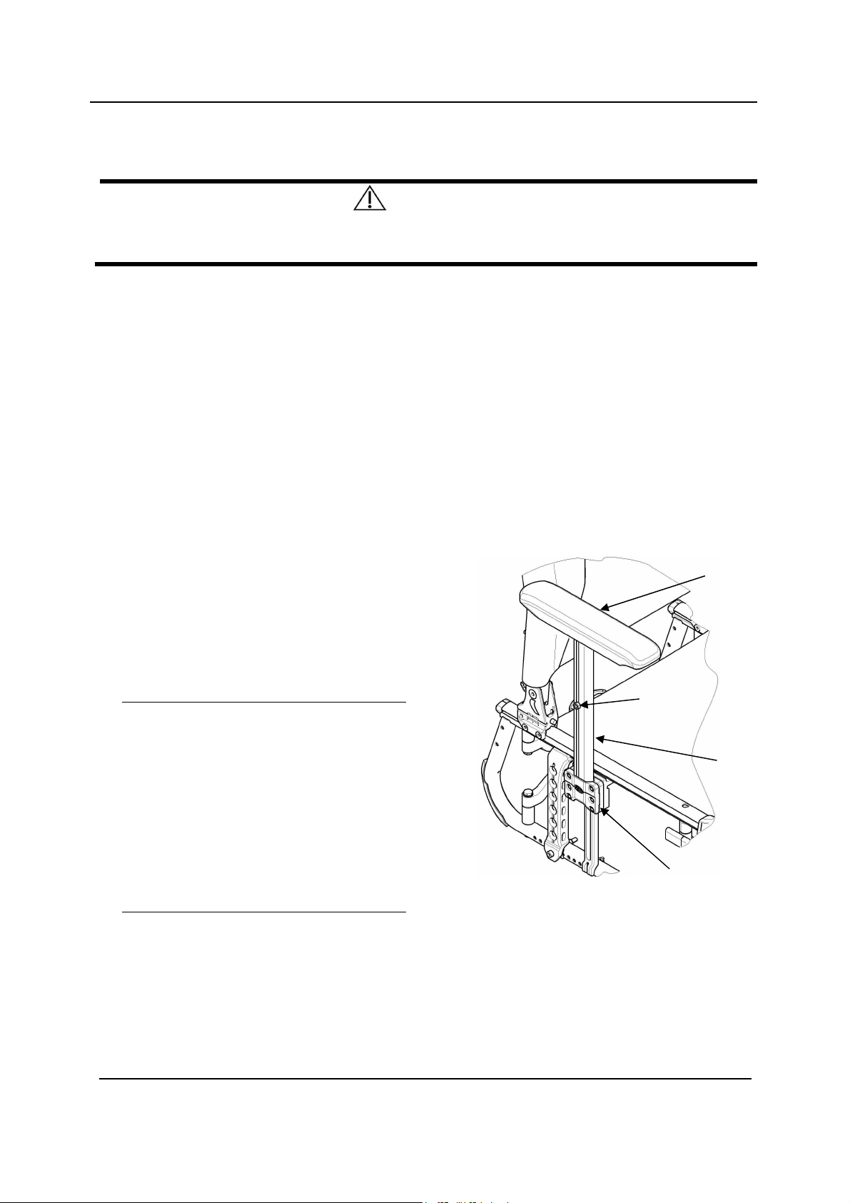
Removing/Installing and Adjusting Removable Armrests
(n°1)
NOTE: For this procedure, refer to FIGURE 3.1.
Removing/Installing removable armrest (n°1)
NOTE: To remove the removable armrest, reverse this procedure.
1. Align the vertical tube with the socket in the T-Arm bracket on the wheelchair frame.
2. Slide the vertical tube into the T-Arm
bracket until the height adjustment screw
rests on the top on the T-Arm bracket.
Adjusting removable armrest
Height
Armrest
NOTE: For this procedure, refer to FIGURE
3.1.
1. Remove the removable armrest. Refer to
Removing/Installing removable armrest
paragraph.
2. Unscrew the Height adjustment screw (M5)
3. Adjust to the desired height adjustment.
Secure tightly the Height adjustment screw
(M5).
4. Both T-arm should be set to the same
position if required.
5. Reinstall the removable armrest. Refer to
Removing/Installing removable armrest
paragraph.
Height adjustment
T-Arm
T-Arm bracket
FIGURE 3.1 Removable armrest
13 M yOn HC
SECTION 3—ARMRESTS
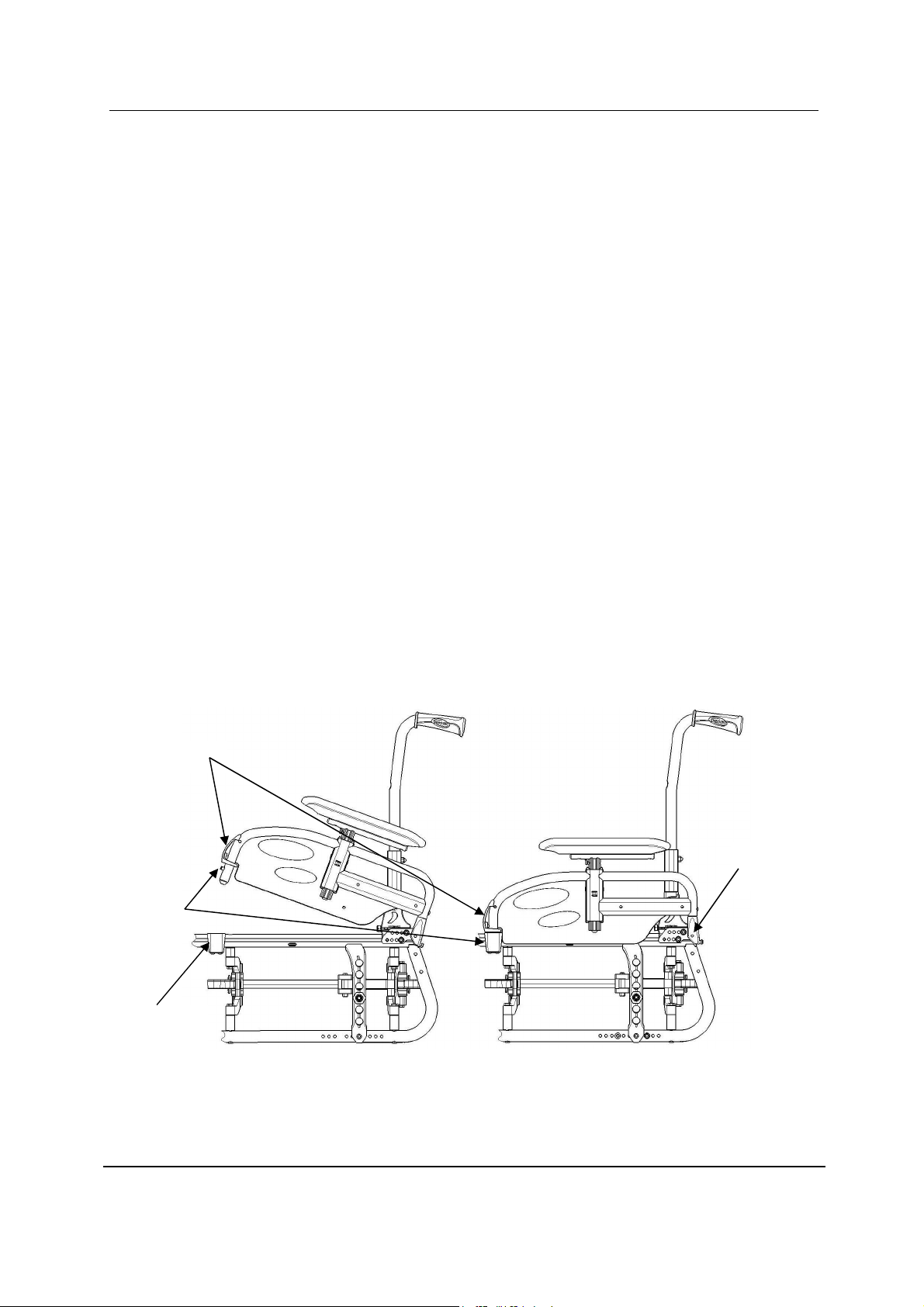
Removing/Installing Swing Away Armrests (n°3)
Removing/Installing Swing Away Armrest (n°3)
NOTE: For this procedure, refer to FIGURE 3.2.
Removing Swing Away Armrest
1.
Unlock existing armrest assembly by operate the push bracket
2. Swing back on the existing armrest to remove from the front arm socket.
3. Pull up on the existing armrest to remove from the rear pivot socket.
4. Repeat STEPS 1-3 for opposite side of wheelchair, if necessary.
Installing Swing Away Armrest
1. If necessary, remove existing armrest assembly as describe above.
2. Install new/existing armrest assembly, first into the rear pivot socket and
into the front arm socket.
.
3. Lock new/existing armrest assembly by operate the push bracket.
Make sure that the dog point is properly engaged in its housing.
4. Repeat STEPS 1-3 for opposite side, if necessary.
Push bracket
Dog point
Front arm
socket
Rear pivot
socket
FIGURE 3.2
MyOn HC 14
Removing/Installing Swing Away Armrest
 Loading...