

Invacare Motion Concepts Ultra Low Maxx Service Manual Supplement
Invacare®UltraLowMaxxby
MotionConcepts
Supplementtopowerwheelchairservicemanual
enModularPowerPositioningSystem
ServiceManual
PROVIDER:Keepthismanual.
TheproceduresinthismanualMUSTbeperformedbyaqualied
technician.

©2019InvacareCorporation
Allrightsreserved.Republication,duplicationormodicationinwholeorinpartisprohibitedwithoutpriorwritten
permissionfromInvacare.Trademarksareidentiedby™and®.AlltrademarksareownedbyorlicensedtoInvacare
Corporationoritssubsidiariesunlessotherwisenoted.

Contents
1General.........................................5
1.1Introduction..................................5
1.2GeneralInformation............................5
1.3NotesonShipping..............................5
1.4SymbolsinThisManual..........................5
1.5ImagesinThisManual..........................5
1.6SystemIdentication............................5
1.7Abbreviations.................................6
2Safety..........................................7
2.1SafetyandFittingInstructions.....................7
3Overview........................................9
3.1Components..................................9
3.1.1OverviewofSeatingSystem....................9
3.1.2BackrestStyles..............................9
3.1.3ArmrestStyles..............................10
3.1.4RemoteBrackets............................11
3.1.5MountingPositionsofLiNXModules.............13
3.1.6LiNXWiringDiagrams.........................13
3.2TighteningTorques.............................13
3.3Imperialtometricconversionchart.................14
3.4ACS2MountingPositionsandWiringDiagrams........14
3.4.1MountingPositionsofACS2Modules.............14
3.4.2WiringdiagramsUltraLowMaxxwithTDXSP2......16
3.4.3WiringdiagramsUltraLowMaxxwithStorm
4Service..........................................24
4.1SystemReviewChecklist.........................24
4.2Inspectionchecklist.............................24
4.3Lubrication...................................25
4.4UpdatingACS2Software.........................25
5SettingsandAdjustments............................29
5.1Measuringcorrectly.............................29
5.2SettingDriveLockoutandLimitSwitches.............29
5.3Centerofgravity(CG)adjustments(forwardandaft)....30
5.3.1Adjustingcenterofgravity.....................31
5.3.2MountingpositionsforTDXSP2.................31
5.3.3MountingpositionsforStorm
4
..................32
6Chassis..........................................34
6.1Replacingtherearsuspensionstrut(Storm
7Seat............................................35
7.1Remove/InstallSeatFrameShrouds.................35
7.2ReplacingSeatPansand/orSideRails...............35
7.3ReplacingPositioningSystemHardware.............36
7.4Replacingtiltactuator...........................36
7.5Replacinglifteractuator.........................36
7.6Removing/Installingseat.........................37
7.7Removing/Installingtiltmodule/lifter/tiltmodule......37
7.8AdjustingSeatDepth............................38
7.9AdjustingSeatWidthandBackrestWidth............38
7.10Adjustingseatheight(TDXSP2)...................39
7.11Settingpre-tilt................................39
7.12Replacingposturebelt..........................40
8Backrests........................................41
8.1ReplacingHighBackAssemblyorBackCover/Foam
Assembly...................................41
8.2Removing/InstallingtheMatrx®BackAssembly—Tilt
Systems....................................41
8.3Removing/InstallingtheMatrx®Back
Assembly—Recline............................42
8.4ReplacingBackCane............................42
8.5ReplacingSeatBackMountingHardware.............43
8.6ReplacingBackrestActuator.......................43
8.7ReplaceElanHeadrestAssembly...................44
8.8AdjustingBackrestHeight—ManualBackrest.........45
8.9AdjustingBackrestHeight—PoweredRecline.........50
8.10AdjustingExtendedShearReduction...............53
8.11Adjustingbackrestpreclineangle..................53
8.12AdjustingAngleofPresetBackrest.................54
8.13AdjustingfoaminsertsofHighBack................54
4
.......20
4
)..........34
9Armrests........................................55
9.1ReplaceArmrestReceiver........................55
9.2ReplacingtheCantileverFlip-UpArmrest.............55
9.3Adjustingcantileverip-uparmrest.................55
9.4ReplacingtheCantileverSeatMountArmrest.........56
9.5UltraRailMountedFlipBackCantileverMaxx
Armrest....................................56
9.6InstallingMultiAxisUpperExtremitySupport
(MACES)....................................57
9.7AdjustarmpadwithMultiAxisUpperExtremity
Support(MACES).............................58
9.8InstallingElbowBlock...........................58
9.9AdjustingElbowBlock...........................58
9.10ArmPadInstallation/Adjustment..................59
9.11Installing/AdjustingTroughArmPad................60
9.12ReplacingHandPad............................60
9.13Adjustingtwopostreclinearmrest.................60
9.14Installing/AdjustingButtonsorToggles..............61
10Legrests........................................62
10.1PivotPluslegrests.............................62
10.1.1SwingawayPivotPluslegrests.................62
10.1.2RemovingPivotPlusLegrests..................62
10.1.3AdjustingangleofPivotPluslegrests............62
10.1.4AdjustingWidth-andAngle-Adjustable
Footplate.................................63
10.1.5ReplacingActuatorofPoweredPivotPlus
Legrest...................................63
10.1.6ReplacingPivotPlusCalfPadAssembly...........63
10.1.7ReplacingFootplateRoller....................64
10.2Center-mountedlegrests—manuallyadjustable......64
10.2.1Installing/RemovingCenterMountedFootrest......64
10.2.2ReplacingCableReleaseFootrestBrace..........65
10.2.3Removing/installingcrossbraceofcenter-mounted
legrest...................................65
10.2.4Removingthelegrest........................65
10.2.5Settingtheangleofthelegrest................66
10.2.6SettingLengthofLegrest.....................66
10.2.7SettingAngleofFootPlate....................66
10.2.8Remove/InstallAdjustableCalfPadHardware......66
10.2.9SettingAngleandHeightofCalfPad............67
10.2.10ReplaceCenterBracketforManualCenter
MountFootrest............................67
10.3LNXlegrest..................................67
10.3.1Removing/installingcrossbraceofside-mounted
legrests..................................67
10.3.2ReplacingLNXpoweredcenter-mountedlegrest
withtelescopingfootboard....................67
10.3.3ReplacingIndependentMountingFootPlate
Hardwareand/orFootPlates..................68
10.3.4ReplacingFootPlatformAssembly..............69
10.3.5ReplacingIndividualCalfPad,CalfPadAssembly
orCover..................................69
10.3.6AdjustingBasicAngleofLNXLegrest............70
10.3.7Settingthelengthofthelegrest................70
10.3.8SettingAngleofFootPlate....................71
10.3.9Adjustingfootplatewidthofcenter-mounted
legrest...................................71
10.3.10SettingAngleofFootboard...................71
10.3.11SettingHeightandWidthofCalfPad...........71
10.4Vari-Ffootrest................................71
10.4.1Swivellingthefootrest/legrestoutwardand/or
removing.................................71
10.4.2Settingtheangle...........................72
10.4.3Settingtheendstopofthefootrest............72
10.4.4Adjustingthelengthofthefootrest.............73
10.5Vari-Alegrests................................73
10.5.1Swivellingthefootrest/legrestoutwardand/or
removing.................................73
10.5.2Settingtheangle...........................73
10.5.3Settingtheendstopofthelegrest..............74
10.5.4Adjustingthelengthofthelegrest..............75
10.5.5Adjustingthedepthofthecalfpad.............75
10.5.6Adjustingtheheightofthecalfpad.............75

Invacare®UltraLowMaxxbyMotionConcepts
10.5.7Unlockingandswivellingthecalfpadbackward
whenalighting.............................75
10.5.8Adjustingtheangle–adjustablefootplate.........75
10.5.9Adjustingtheangle–anddepth–adjustablefoot
plate....................................76
10.6ADMlegrests................................76
10.6.1Swivellingthelegrestoutwardand/orremoving....76
10.6.2Settingtheangle...........................76
10.6.3Adjustingthelengthofthelegrest..............76
10.6.4Adjustingthedepthofthecalfpad.............76
10.6.5Adjustingtheheightofthecalfpad.............77
10.6.6Unlockingandswivellingthecalfpadbackward
whenalighting.............................77
10.6.7Adjustingtheangle–adjustablefootplate.........77
10.6.8Adjustingtheangle–anddepth–adjustablefoot
plate....................................77
10.7Poweredelevatinglegrests(ADElegrests)............78
10.7.1Swivellingthelegrestoutwardand/orremoving....78
10.7.2Settingtheangle...........................78
10.7.3Adjustingthelengthofthelegrest..............78
10.7.4Adjustingthedepthofthecalfpad.............78
10.7.5Adjustingtheheightofthecalfpad.............78
10.7.6Unlockingandswivellingthecalfpadbackward
whenalighting.............................79
10.7.7Adjustingtheangle–adjustablefootplate.........79
10.7.8Adjustingtheangle–anddepth–adjustablefoot
plate....................................79
11PositioningOptions...............................80
11.1Hipsupportwithquickrelease...................80
11.2LateralTrunkSupportAdjustments.................81
11.3Headrests...................................81
11.3.1Adjustingtheheadrest.......................81
11.3.2InstallingheadrestadapterforEliteandHigh
Backs....................................82
11.3.3Auto–styleheadrestset-upandinstallation........82
11.3.4AdjustingElanHeadrestHardware..............82
11.3.5Adjustingmulti-axisheadresthardware...........83
12PrimaryRemotes.................................85
12.1AdjustmentPossibilityforRemote.................85
12.1.1AdjustingRemoteHeight(onlyforSwing–Away
RemoteSupports)...........................85
12.1.2AdjustingRemoteOffset......................85
12.1.3InstallingStandardRemoteHolderforLiNX
Remotes..................................85
12.1.4InstallingSwing-AwayRemoteHolderforLiNX
Remotes..................................85
12.2AdjustingSwing-AwayDisplayHolder...............86
12.3QuadLink...................................86
12.3.1InstallingRemoteontoQuadLink(untilFebruary
2017)....................................86
12.3.2ReversingMountingPositionofRemote(until
February2017).............................87
12.3.3Securingtheremotecable....................88
12.3.4InstallingLiNXRemoteontoQuadLink...........88
12.3.5ReversingMountingPositionofRemote(asof
February2017).............................88
12.3.6Adjustingremoteheight......................89
12.3.7Adjustingremoteposition....................89
12.3.8AdjustingLockT ension.......................89
12.4NucleusMidlineHolder.........................90
12.4.1InstallingNucleusMidlineHolder...............90
12.4.2AdjustingDepthofMidlineHolder..............90
12.4.3AdjustingHeightofNucleusMidlineHolder.......90
12.4.4AdjustingJoystick/DisplayPositiononNucleus
MidlineHolder.............................90
13SecondaryInputs—User...........................92
13.1AdjustingManualChinControl....................92
13.1.1AdjustingExtremityControlJoystick.............92
13.1.2AdjustingEggSwitch........................92
13.2AdjustingHeadArray...........................92
13.3AdjustingSipandPuffHeadArray.................92
13.4AdjustingSwing-AwayMechanism.................93
13.5ReplacingLipswitch............................93
14SecondaryInputs—Attendant.......................94
14.1InstallingBracketforAttendantRemoteHolder.......94
14.2InstallingClampforDLX-ACU200RemoteHolderon
ManualBackrest..............................94
15AuxiliaryModules................................95
15.1ReplacingInputModuleDLX-IN500................95
15.2ReplacingOutputModuleDLX-OUT500.............95
15.3ReplacingActuatorModuleDLX-ACT400.............96
4
1586649-F
General
1General
1.1Introduction
Thisdocumentcontainsimportantinformationabout
assembly,adjustmentandadvancedmaintenanceofa
productcomponent.Toensuresafetywhenhandlingthe
component,readthisdocument,theservicemanualsof
thebaseproductandadditionalcomponents,andtheuser
manualscarefullyandfollowthesafetyinstructions.
ThecomponentitselfdoesnotbearaCEmarking,butitis
partofaproductthatcomplieswiththerespectivevalid
regulationsconcerningmedicaldevices.Thecomponents
isthereforecoveredbytheCEmarkingoftheproduct.
FindtheusermanualonInvacare’swebsiteorcontact
yourInvacarerepresentative.Seeaddressesattheend
ofthisdocument.
Invacarereservestherighttoalterproductspecications
withoutfurthernotice.
Beforereadingthisdocument,makesureyouhavethe
latestversion.Y oundthelatestversionasaPDFonthe
Invacarewebsite.
Forpre-saleanduserinformation,seetheusermanual.
Formoreinformationabouttheproduct,forexample
productsafetynoticesandproductrecalls,contactyour
Invacarerepresentative.Seeaddressesattheendofthis
document.
1.2GeneralInformation
Serviceandmaintenanceworkmustbecarriedouttaking
thisdocumentintoaccount.
Itisimperativethatyouobservesafetyinformation.
Informationaboutoperationoraboutgeneralmaintenance
andcareworkontheproductshouldbetakenfrom
servicemanual.
overhaulworkleadtotheexclusionofallliabilityonthe
sideofInvacare.
Ifyouhaveanyproblemsorquestionscontactyour
provider .
1.3NotesonShipping
•Ifthemobilitydevicehastobeshippedbacktothe
manufacturerformajorrepairs,youshouldalways
usetheoriginalpackagingfortransport.
•Pleaseattachaprecisedescriptionofthefault.
1.4SymbolsinThisManual
Symbolsandsignalwordsareusedinthismanualand
applytohazardsorunsafepracticeswhichcouldresultin
personalinjuryorpropertydamage.Seetheinformation
belowfordenitionsofthesignalwords.
WARNING
Indicatesahazardoussituationthatcould
resultinseriousinjuryordeathifitisnot
avoided.
CAUTION
Indicatesahazardoussituationthatcould
resultinminororslightinjuryifitisnot
avoided.
IMPORTANT
Indicatesahazardoussituationthatcould
resultindamagetopropertyifitisnot
avoided.
Tips
Givesusefultips,recommendationsand
informationforefcient,trouble-freeuse.
Tools
Identiesrequiredtools,componentsand
itemswhichareneededtocarryoutcertain
work.
Assemblyofaccessoriesmightnotbedescribedinthis
document.Refertothemanualdeliveredwiththe
accessory.Additionalmanualscanbeorderedfrom
Invacare.Seeaddressesattheendofthisdocument.
Youcanndinformationaboutorderingsparepartsin
thesparepartscatalogue.
SparepartsmustmatchoriginalInvacareparts.Onlyuse
sparepartswhichhavebeenapprovedbyInvacare.
Theproductmayonlybemaintainedandoverhauledby
qualiedpersonnel.
Theminimumrequirementforservicetechniciansis
suitabletraining,suchasinthecycleororthopedic
mechanicselds,orsufcientlylong-termjobexperience.
Experienceintheuseofelectricalmeasuringequipment
(multimeters)isalsoarequirement.SpecialInvacare
trainingisrecommended.
Alterationstothemobilitydevicewhichoccurasaresult
ofincorrectlyorimproperlyexecutedmaintenanceor
1.5ImagesinThisManual
Thedetailedimagesinthismanualaregivenmarksto
identifyvariouscomponents.Componentmarksintext
andoperationalinstructionsalwaysrelatetotheimage
directlyabove.
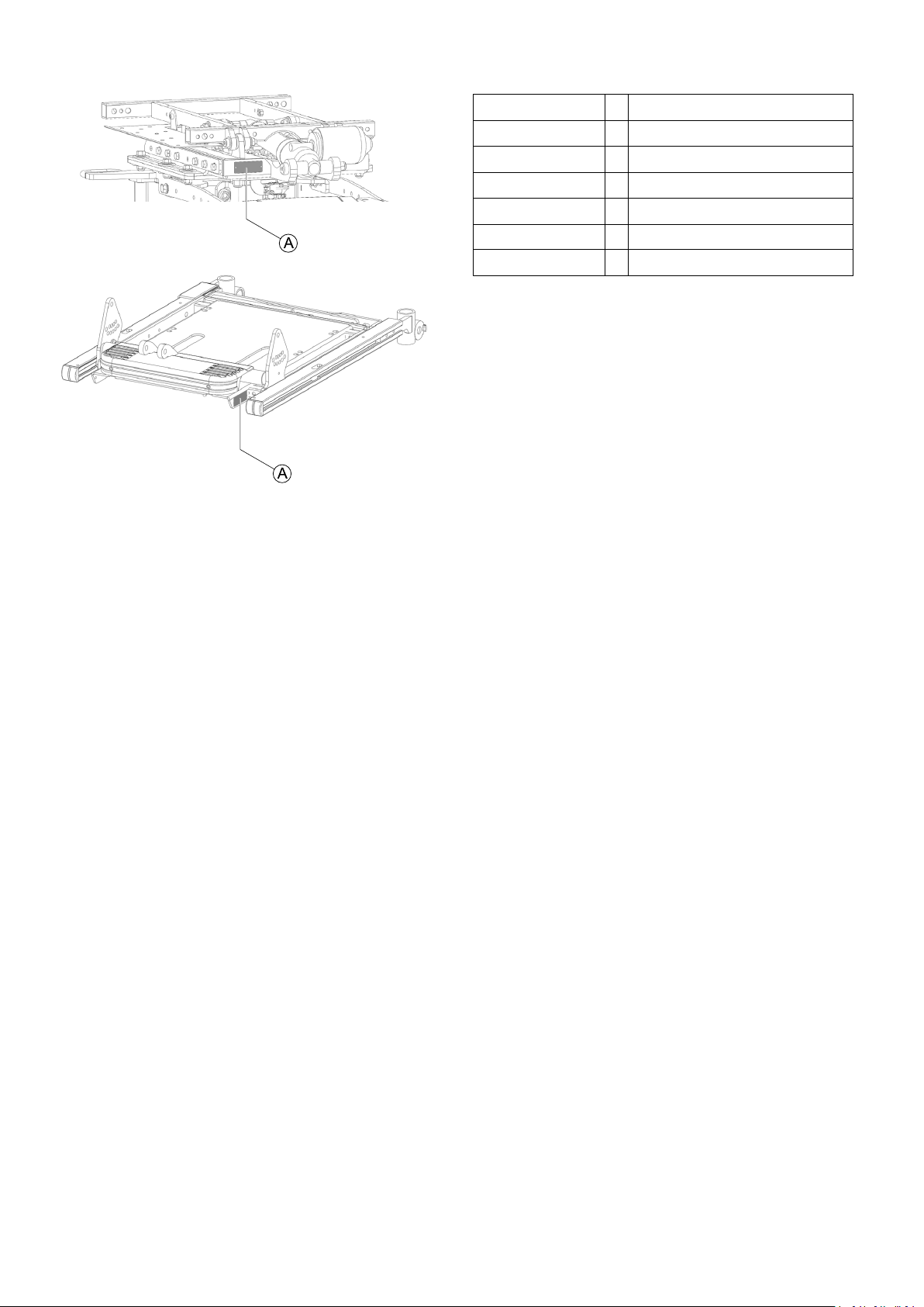
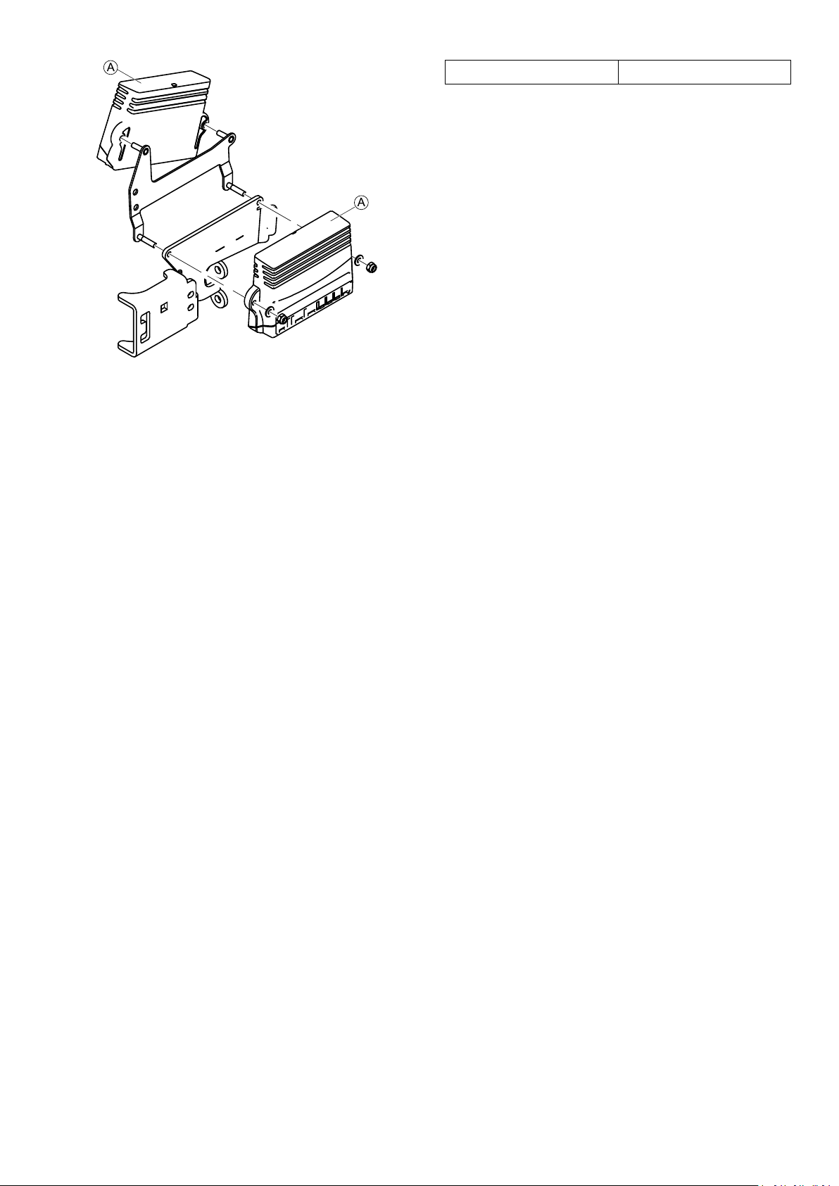
1.6SystemIdentication
EachMotionConceptsseatingsystemisidentiedby
auniqueserialnumber,whichallowsustotracethe
productionhistoryofthesystemandbetterequips
ustoaddressanyserviceissuesthatmayoccurover
thelifetimeoftheproduct.Thelocationoftheserial
numberidenticationplatevariesdependingonthetype
ofpositioningsysteminstalled.Therearetwopossible
mountinglocationsasindicatedintheimagesbelow.
1586649-F5
Invacare®UltraLowMaxxbyMotionConcepts
1.7Abbreviations
Abbreviation
CG
DLO
ESR
PES
PPS
STF
Meaning
=
CenterofGravity
=
DriveLockout
=
ExtendedShearReduction
=
PowerElevatingSeat
=
PowerPositioningSystem
=
Seat-To-FloorHeight
61586649-F

Safety
2Safety
2.1SafetyandFittingInstructions
Thesesafetyinstructionsareintendedtopreventaccidents
atwork,anditisimperativethattheyareobserved.
Beforeanyinspectionorrepairwork
•Readandobservethisrepairmanualandthe
associatedusermanual.
•Observetheminimumrequirementsforcarryingout
thework(see1.2GeneralInformation,page5).
PersonalSafetyEquipment
Safetyshoes
Themobilitydevice,andsomeofitscomponents,arevery
heavy.Thesepartscanresultininjuriestothefeetifthey
areallowedtodrop.
•Wearstandardizedsafetyshoesduringallwork.
Eyeprotection
Itispossiblethatbatteryacidcanbedischargedwhen
workingondefectivebatteriesorwhenhandlingbatteries
improperly.
•Alwaysweareyeprotectionwhenworkingonany
defectiveorpossiblydefectivebatteries.
Safetygloves
Itispossiblethatbatteryacidcanbedischargedwhen
workingondefectivebatteriesorwhenhandlingbatteries
improperly.
•Alwayswearacid-proofsafetygloveswhenworking
onanydefectiveorpossiblydefectivebatteries.
GeneralSafetyInformationandInformationAboutFitting
/Removal
DANGER!
RiskofDeath,SeriousInjury,orDamage
Lightedcigarettesdroppedontoanupholstered
seatingsystemcancauseareresultingin
death,seriousinjury,ordamage.Mobility
deviceoccupantsareatparticularriskofdeath
orseriousinjuryfromtheseresandresulting
fumesbecausetheymaynothavetheabilityto
moveawayfromthemobilitydevice.
–DONOTsmokewhileusingthismobility
device.
WARNING!
RiskofSeriousInjuryorDamage
Storingorusingthemobilitydevicenearopen
ameorcombustibleproductscanresultin
seriousinjuryordamage.
–Avoidstoringorusingthemobilitydevice
nearopenameorcombustibleproducts.
CAUTION!
Riskofcrushing
Variouscomponentssuchasthedriveunit,
batteries,seatetcareveryheavy.Thisresults
ininjuryhazardstoyourhands.
–Notethehighweightofsomecomponents.
Thisappliesespeciallytotheremovalofdrive
units,batteriesandtheseat.
CAUTION!
Injuryhazardifthemobilitydevicestarts
movingunintentionallyduringrepairwork
–Switchthepowersupplyoff(ON/OFFkey).
–Engagethedrive.
–Beforeliftingup,securethemobilitydevice
byusingchockstoblockthewheels.
CAUTION!
Fireandburnhazardduetoelectrical
short-circuit
–Themobilitydevicemustbecompletely
switchedoffbeforeremovalof
voltage-carryingcomponents!T odo
this,removethebatteries.
–Avoidshort-circuitingthecontacts
whencarryingoutmeasurementson
voltage-carryingcomponents.
CAUTION!
Riskofburnsfromhotsurfacesonthemotor
–Allowthemotorstocooldownbefore
commencingworkonthem.
CAUTION!
Injuryhazardandriskofdamagetomobility
deviceduetoimproperorincomplete
maintenancework
–Useonlyundamagedtoolsingoodcondition.
–Somemovingpartsaremountedinsockets
withPTFEcoating(Teon™).Nevergrease
thesesockets!
–Neveruse"normal"nutsinsteadof
self-lockingnuts.
–Alwaysusecorrectly-dimensionedwashers
andspacers.
–Whenreassembling,alwaysreplaceanycable
tieswhichwerecutduringdismantling.
–Aftercompletingyourwork/beforerenewed
start-upofthemobilitydevice,checkall
connectionsfortighttting.
–Aftercompletingyourwork/beforerenewed
start-upofthemobilitydevice,checkallparts
forcorrectlocking.
–Onlyoperatethemobilitydevicewiththe
approvedtyrepressures(seetechnicaldata).
–Checkallelectricalcomponentsforcorrect
function.Notethatincorrectpolaritycan
resultindamagetothecontrolsystem.
–Alwayscarryoutatrialrunattheendof
yourwork.
CAUTION!
Riskofinjuryanddamagetoproperty,ifthe
maximumspeedreductiononawheelchair
withalifterdoesnotfunctioncorrectly
Thewheelchair’scontrolunitmustreducethe
maximumpossiblespeedassoonasthelifter
israised.
–Testthemaximumspeedreductionfor
correctfunctionafteranymaintenancework
ormodicationstothewheelchair .
1586649-F
7

Invacare®UltraLowMaxxbyMotionConcepts
CAUTION!
Anychangestothedriveprogramcanaffect
thedrivingcharacteristicsandthetipping
stabilityofthemobilitydevice
–Changestothedriveprogrammayonlybe
carriedoutbytrainedInvacareproviders.
–Invacaresuppliesallmobilitydeviceswitha
standarddriveprogramex-works.Invacare
canonlygiveawarrantyforsafemobility
devicedrivingbehavior-especiallytipping
stability-forthisstandarddriveprogram.
Markallcurrentsettingsforthemobilitydevice
(seat,armrests,backrestetc.),andtheassociated
cableconnectingplugs,beforedismantling.This
makesreassemblyeasier.Allplugsarettedwith
mechanicallockswhichpreventreleaseofthe
connectingplugsduringoperation.Toreleasethe
connectingplugsthesafetylocksmustbepressed
in.Whenreassemblingensurethatthesesafety
locksarecorrectlyengaged.
81586649-F
Overview
3Overview
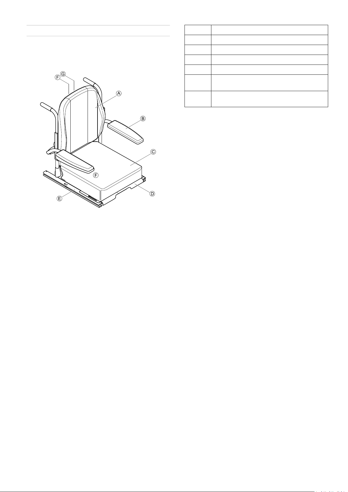
3.1Components
3.1.1OverviewofSeatingSystem
A
B
C
D
E
F
G
Backrest,see3.1.2BackrestStyles,page9
Armrest,see3.1.3ArmrestStyles,page10
Cushion
Seatplate
Siderail
Remotebracket,see3.1.4RemoteBrackets,
page11
Remotebracketforattendant,see3.1.4
RemoteBrackets,page11
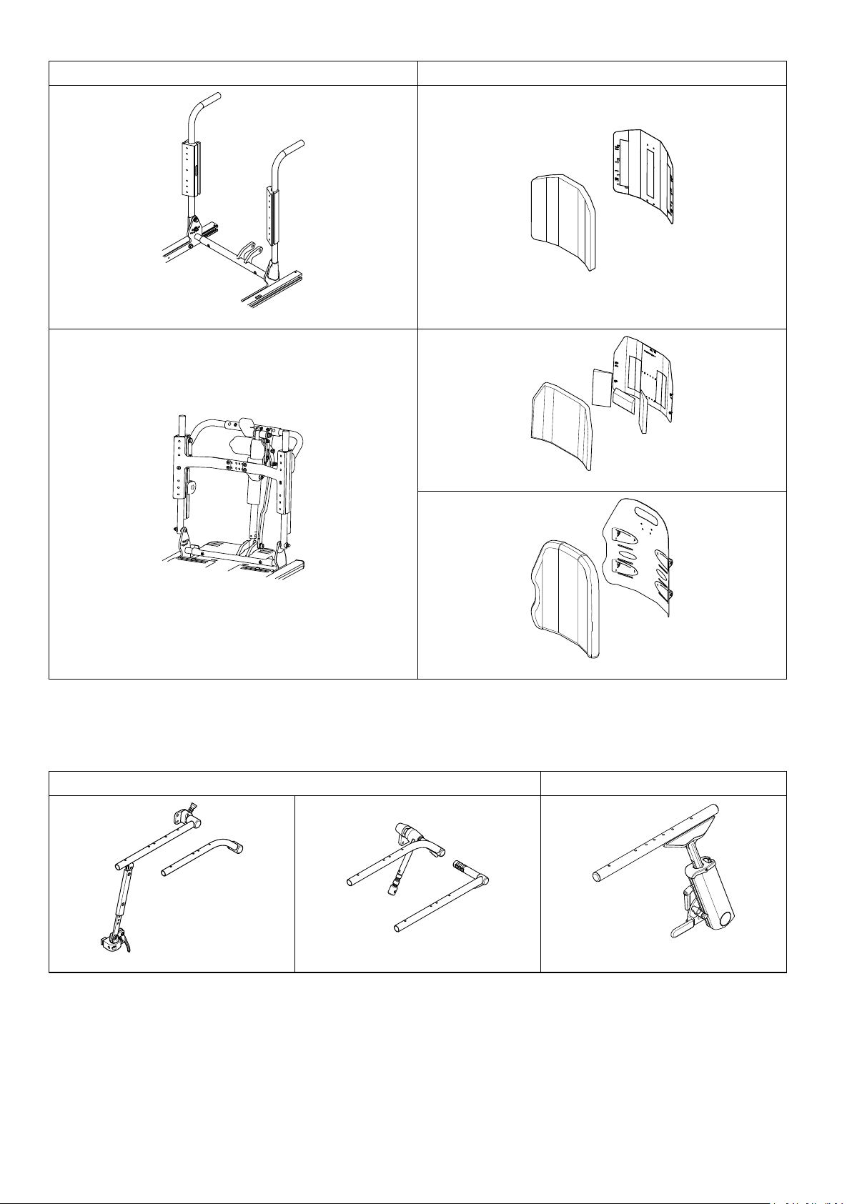
3.1.2BackrestStyles
Fig.3-1
TheUltraLowMaxxseatisavailablewithdifferentbackreststyles.
1586649-F9
Invacare®UltraLowMaxxbyMotionConcepts
BackrestFrameBackrestStyle
Fig.3-2ManualRecline
Fig.3-3StandardRehabBack
Fig.3-5HighBack
Fig.3-4PoweredReclinewithESR
Fig.3-6MatrxBacks
3.1.3ArmrestStyles
TheUltraLowMaxxseatisavailablewithdifferentarmreststyles.Forremotebracketsthatcanbemountedtoarmrest,
see3.1.4RemoteBrackets,page11.
ForPoweredReclineForManualRecline
Fig.3-8BackpostMountedFlipBackCantilever
Fig.3-7TwoPostRecline
Fig.3-9UltraRailMountedFlipBack
CantileverMaxx
Armpadstyles
AllUltraLowMaxxarmrestsareavailablewiththefollowingarmpads:
101586649-F
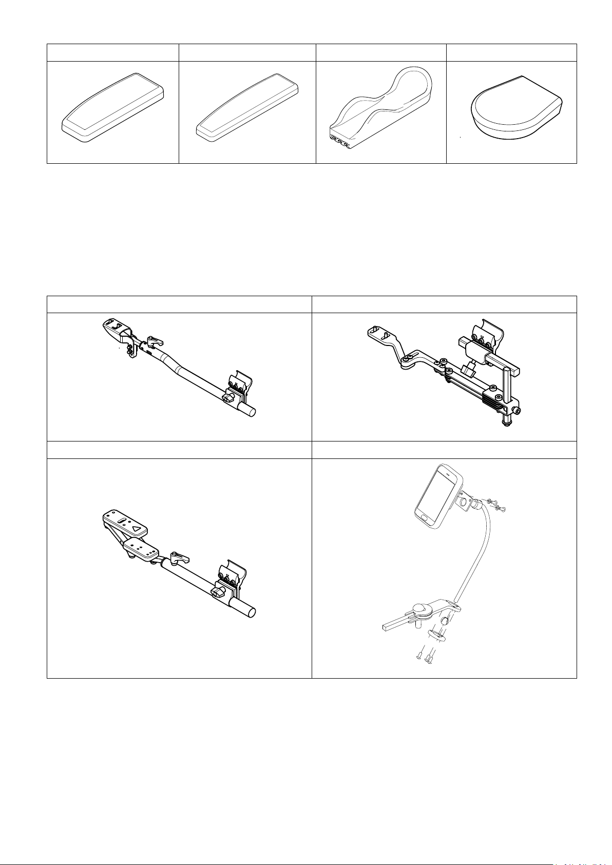
DeskArmpadFullLengthArmpadErgonomicArmtroughFlatHandPad
Overview
Fig.3-10
Fig.3-11
Fig.3-12
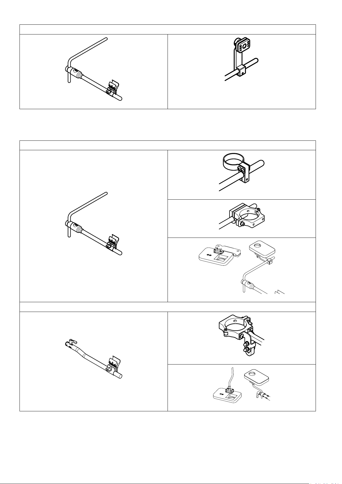
3.1.4RemoteBrackets
UltraLowMaxxcanbettedwithdifferentbracketsforremotes:
•PrimaryRemotesforUsers,page11
•SecondaryInputsforUsers,page12
•RemotesforAttendant,page12
PrimaryRemotesforUsers
Remotesforthewheelchairuserareinstalledataslotatthearmrestoronnucleusmidlineholder.
StandardwithSupportTubeStandardwithSwing-AwayBracket
Fig.3-14
QuadLinkREM500Swing-AwayDisplayHolder
Fig.3-15
Fig.3-13
Fig.3-16
Fig.3-17
1586649-F
11
Invacare®UltraLowMaxxbyMotionConcepts
NucleusMidlineHolderforREM500
Fig.3-19
Fig.3-18
UltraLowMaxxwithnucleusmidlineholdercancarryadditionalbrackets,remotesandswitches.Anadapterisneeded
toinstallnucleusmidlineholdertoslotatthearmrest.
SecondaryInputsforUsers
NucleusMidlineHolder
SupportTube
Fig.3-21
Fig.3-22
Fig.3-20
Fig.3-23
Fig.3-25
Fig.3-24
Fig.3-26
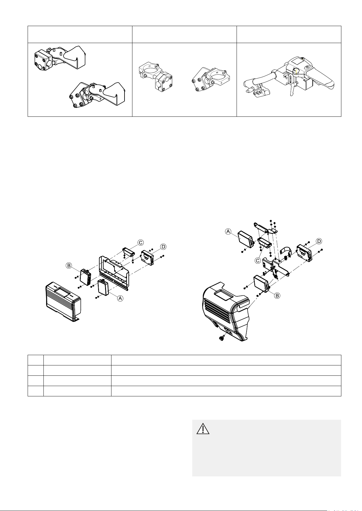
RemotesforAttendant
Remotebracketforthewheelchairattendantisinstalledatthepushbaroratthepushhandlesatthebackrestframe
ofthepowerwheelchair .
12
1586649-F
Overview
AttendantRemoteBracketforPrimary
Remotes
Fig.3-27
AttendantRemoteBracketfor
SecondaryInputs
Fig.3-28
AttendantRemoteBracketforIDC
Fig.3-29
Remotebracketcanbemountedinavarietyofpositions.
3.1.5MountingPositionsofLiNXModules
Thischapteronlyshowsthemountingpositionsofmodulesinstalledonthebackrest.Youndmoreinformationabout
thefollowingcomponentsintheLiNXservicemanual:
•Remotemodules
•ASLcomponents
•Powermodules
•LiNXseatingmodulesandinterfaces
•Poweredseatingaccessories
•Powermodulemounting
•MountingpositionsofpowermodulesandDLX-ACT400onthewheelchair
Fig.3-30ManualBackrest
Fig.3-31PoweredBackrest
DLX-OUT500
A
DLX-IN500
B
GLM-CONX4
C
DLX-ACT400
D
3.1.6LiNXWiringDiagrams
WiringdiagramsforLiNXaredescribedintheLiNXservice
manual.
Outputmodule
Inputmodule
Busexpansionblock
Actuatormodule
3.2TighteningTorques
CAUTION!
Riskofdamagetomobilitydevicedueto
improperlytightenedscrews,nutsorplastic
connections.
–Alwaystightenscrews,nutsetc.tothestated
tighteningtorque.
–Onlytightenscrewsornutswhicharenot
listedherengertight.
1586649-F13

Invacare®UltraLowMaxxbyMotionConcepts
Thetighteningtorquesstatedinthefollowinglistare
basedonthethreaddiameterforthenutsandboltsfor
whichnospecicvalueshavebeendetermined.Allvalues
assumedryandde-greasedthreads.
ThreadTighteningT orquein
Nm±10%
M43Nm
M5
M610Nm
M825Nm
M1049Nm
M1280Nm
M14120Nm
M16180Nm
6Nm
3.3Imperialtometricconversionchart
Youcanusethischartasanorientationtondtheright
toolsize.
IMPERIALMETRIC
inch
5/64
3/32
7/64
1/8
9/64
5/32
11/64
3/16
13/64
7/32
15/64
1/4
17/64
9/32
19/64
5/16
21/64
11/32
23/64
3/8
25/64
13/32
mm
1.9844
2.3813
2.7781
3.1750
3.5719
3.9688
4.3656
4.7625
5.1594
5.5563
5.9531
6.3500
6.7469
7.1438
7.5406
7.9375
8.3344
8.7313
9.1281
9.5250
9.9219
10.3188
IMPERIALMETRIC
inch
27/64
7/16
29/64
15/32
31/64
1/2
33/64
17/32
35/64
9/16
37/64
19/32
39/64
5/8
41/64
21/32
43/64
11/16
45/64
23/32
47/64
3/4
49/64
25/32
51/64
13/16
53/64
27/32
55/64
7/8
mm
10.7156
11.1125
11.5094
11.9063
12.3031
12.7000
13.0969
13.4938
13.8906
14.2875
14.6844
15.0813
15.4781
15.8750
16.2719
16.6688
17.0656
17.4625
17.8594
18.2563
18.6531
19.0500
19.4469
19.8438
20.2406
20.6375
21.0344
21.4313
21.8281
22.2250
3.4ACS2MountingPositionsand WiringDiagrams
3.4.1MountingPositionsofACS2Modules
Thischapteronlyshowsthemountingpositionsofmodules
installedonthebackrest.Y oundinformationabout
othercomponentsintheservicemanualofthepower
wheelchair.
14
1586649-F
Overview
Fig.3-32
A
DX2–ACT2orDX2–ACT4
1586649-F15
Invacare®UltraLowMaxxbyMotionConcepts
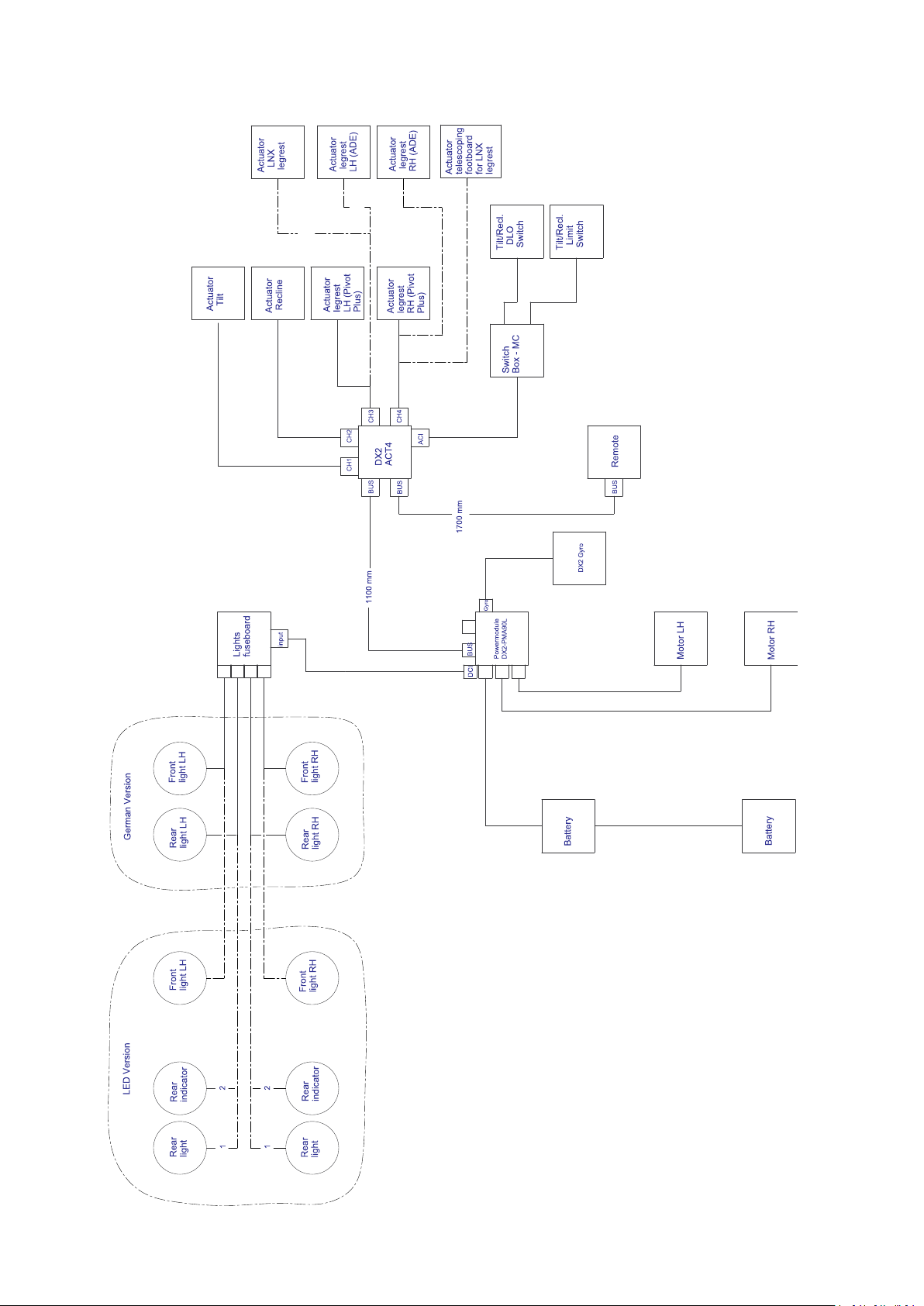
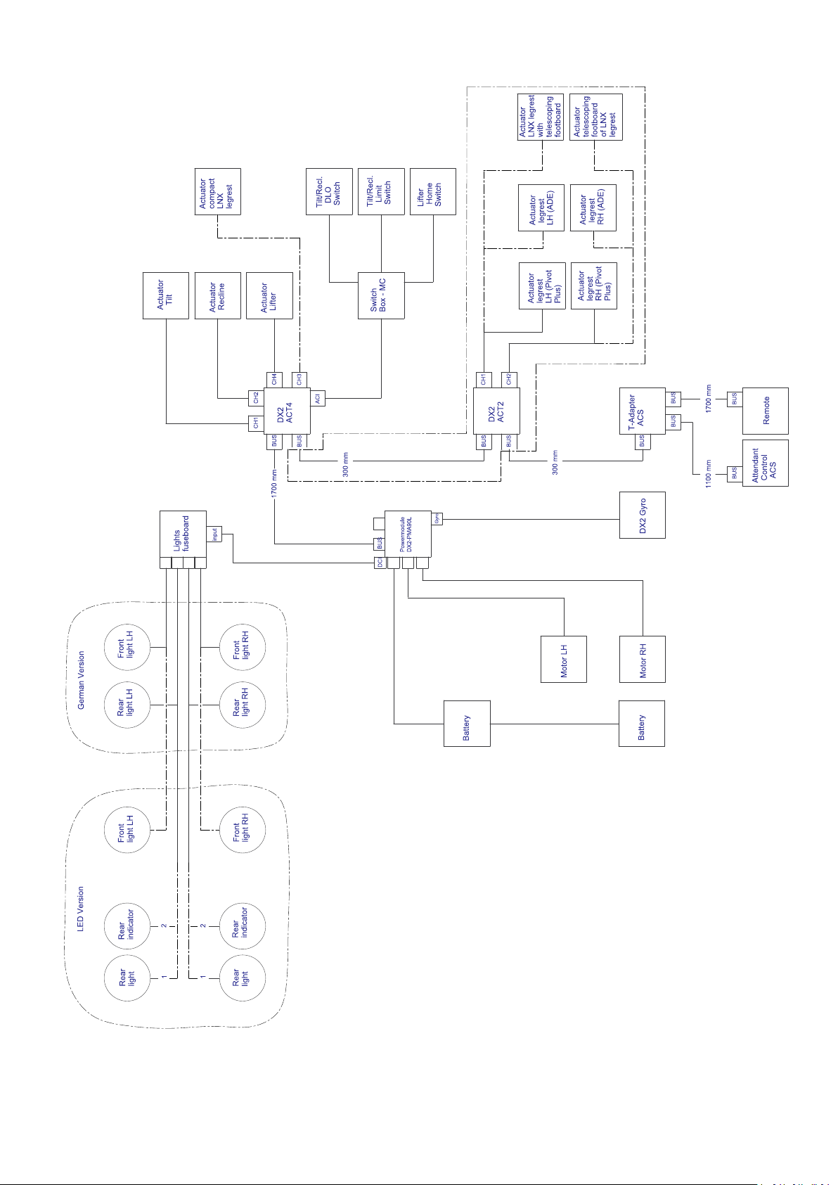
3.4.2WiringdiagramsUltraLowMaxxwithTDXSP2
Wiringdiagramtilt/recline(TDXSP2)
161586649-F
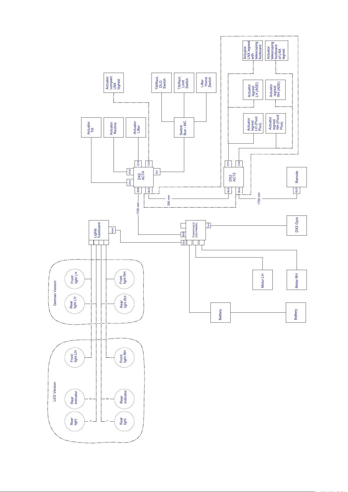
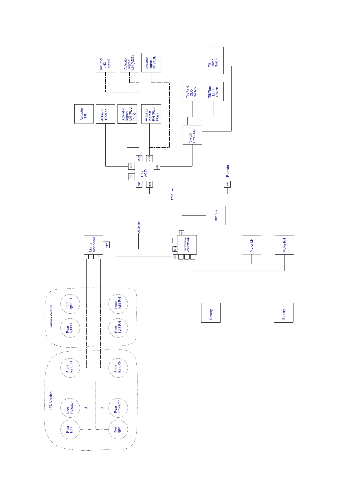
Wiringdiagramlifter/tilt/recline(TDXSP2)
Overview
1586649-F
17
Invacare®UltraLowMaxxbyMotionConcepts
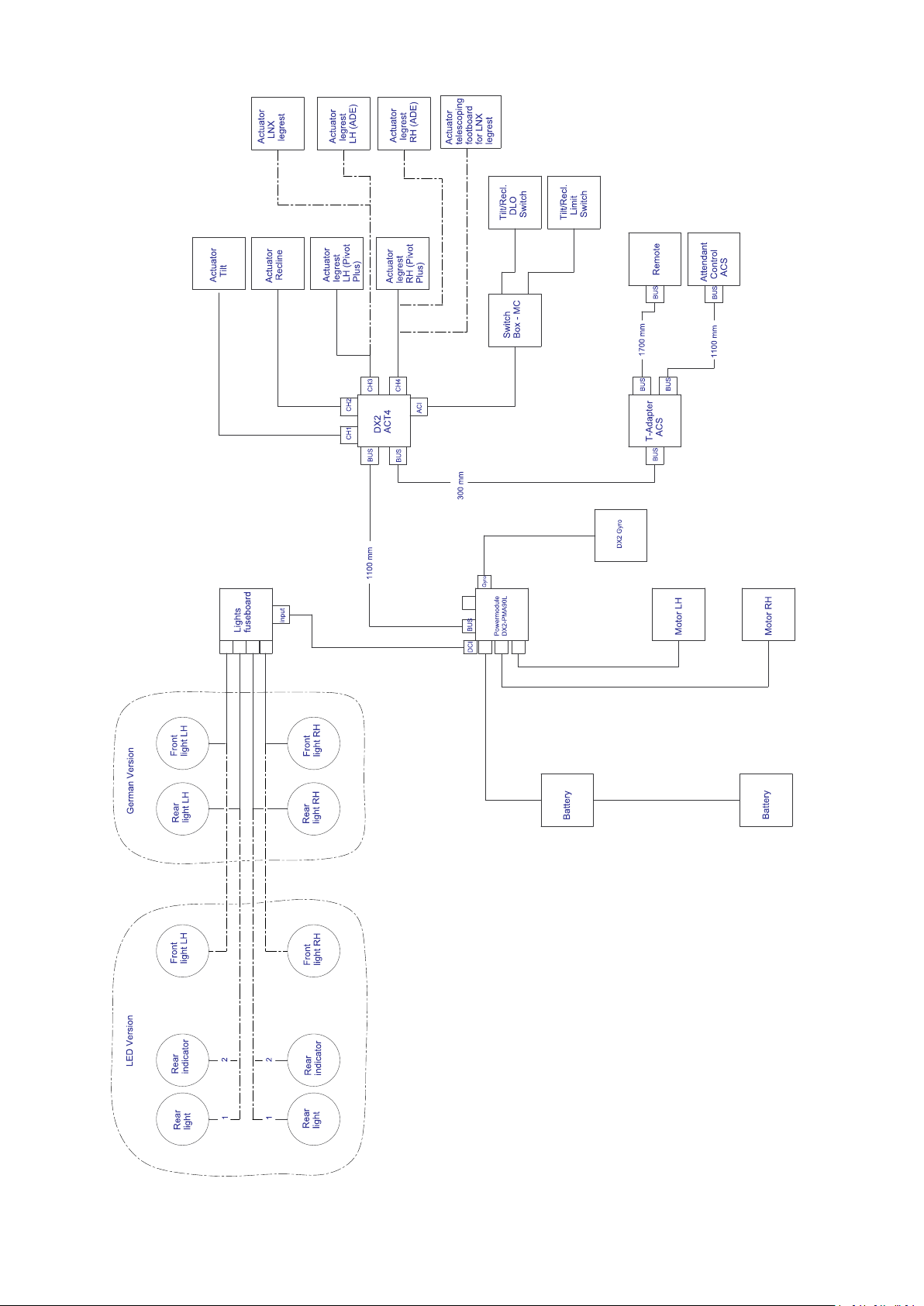
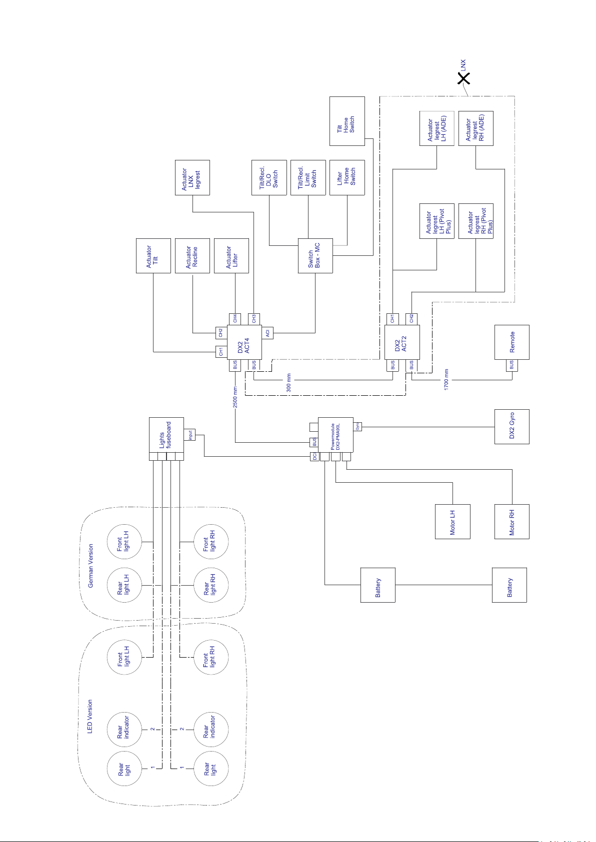
Wiringdiagramtilt/reclineandattendantcontrol(TDXSP2)
181586649-F
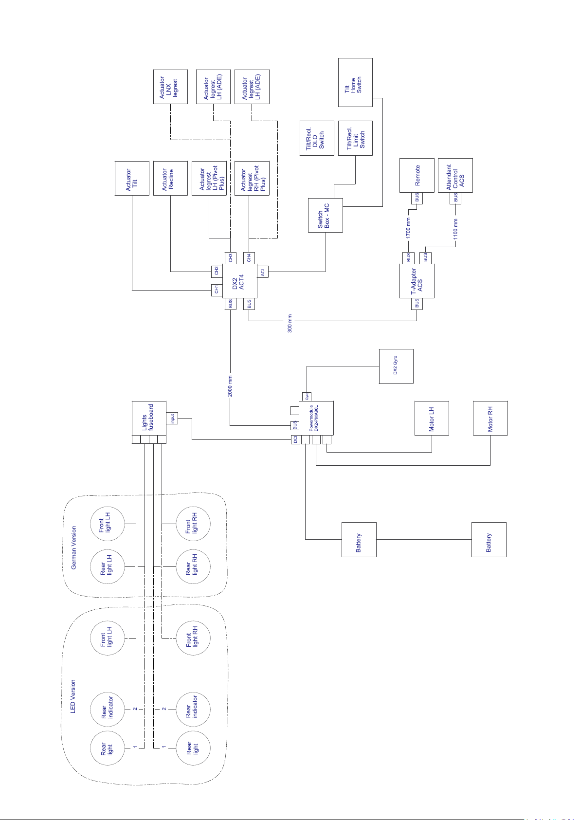
Wiringdiagramlifter/tilt/reclineandattendantcontrol(TDXSP2)
Overview
1586649-F19
Invacare®UltraLowMaxxbyMotionConcepts
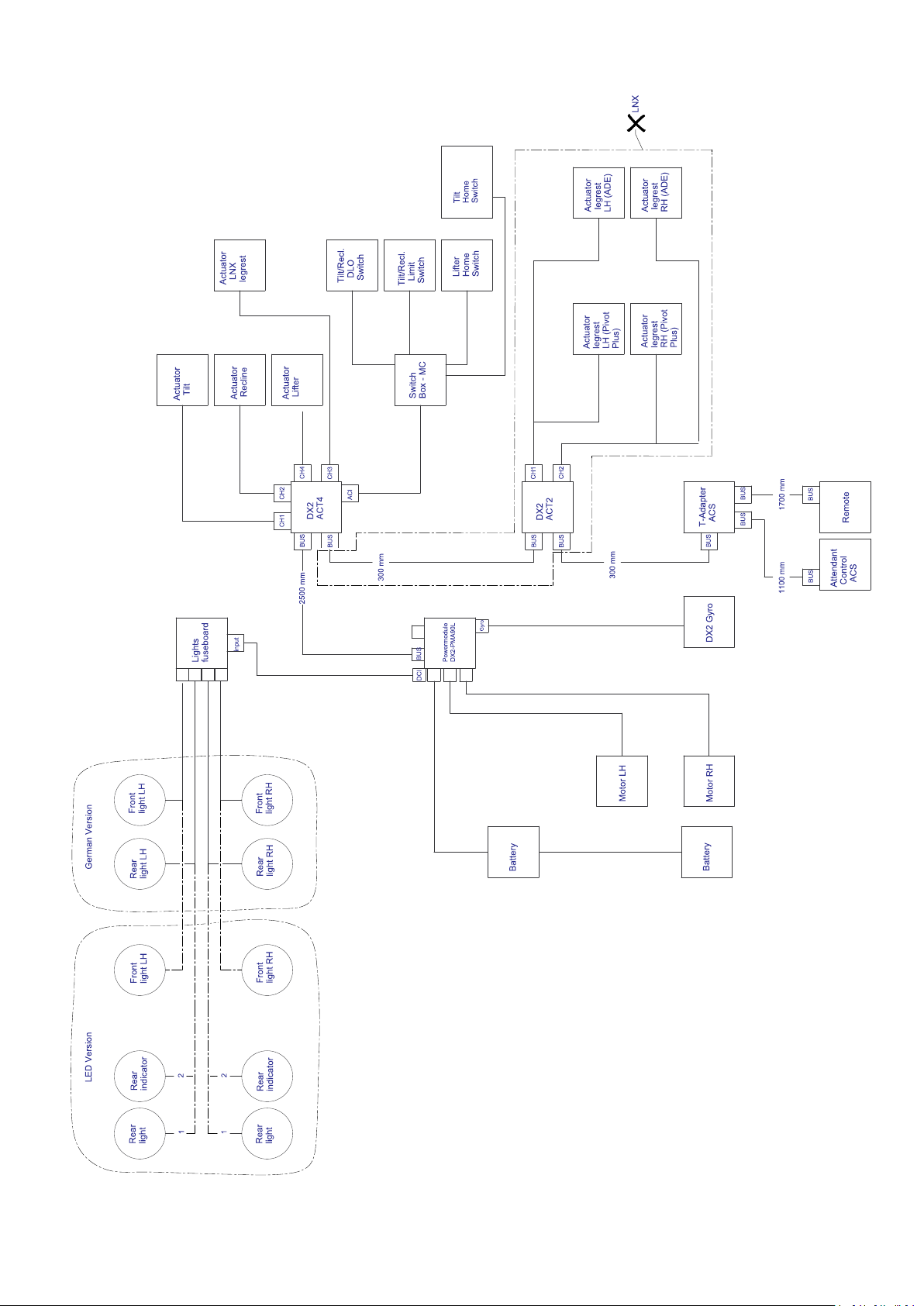
3.4.3WiringdiagramsUltraLowMaxxwithStorm
Wiringdiagramtilt/recline(Storm
4
)
4
201586649-F
Overview
Wiringdiagramlifter/tilt/recline(Storm
4
)
1586649-F
21
Invacare®UltraLowMaxxbyMotionConcepts
Wiringdiagramtilt/reclineandattendantcontrol(Storm
4
)
22
1586649-F
Overview
Wiringdiagramlifter/tilt/reclineandattendantcontrol(Storm
4
)
1586649-F23

Invacare®UltraLowMaxxbyMotionConcepts
4Service
4.1SystemReviewChecklist
Followinganyinstallation,set-upand/oradjustment
relatedtotheseatingsystemalwaystestthe
systemoveritsfullrangeofpositioningfunctions
toensureallmotors,safetylimitsarefunctioning
correctly.Verifythatallmountinghardwareand
criticalcomponentsarealsoinstalled/adjusted
properly.
Thefollowingchecklistisprovidedasareferencewhen
conductinganalreview/inspectionofthewheelchair.
•Checkallfasteners/mountinghardwaretoensurethat
theyhavebeenproperlytightened.
•Checkthedrivelockoutlimitisfunctioning.
•Checkthereducedspeeddrive(ifapplicable)
•Checkthetilt(tilt/recline)limit(ifapplicable).
•Checkthefullrangeoftiltandreclineandlifter(as
applicable).Makecertainthatthereisnointerference.
Makesurethatthewheelchairisstablewiththeuser
initovertheentirerange.
4.2Inspectionchecklist
•Checkpowerlegrestfunction(ifapplicable).Ensure
thereisappropriategroundclearanceintheretracted
position,andcheckforinterferenceoverthefull
rangeoftravel.
•Checkallwiresandcablesoverthecomplete
tilt/recline/lifterrangeforpulling,crushingortight
bends.
•Checkthatthechargerfunctionsproperly.
•Checkthattheaccelerationanddecelerationof
thewheelchairhavebeenprogrammedtolevels
appropriatefortheuser .
•Checkallofthewheelchairdrivefunctions.
•Checkthattherod-endsonthetiltandrecline
actuatorshavebeenproperlypinned(ifapplicable).
•Checktheanti-tipperlatchingsystem(ifapplicable).
•Ifthefrontorrearanti-tippersareadjustable,check
thattheyhavebeensettotheappropriateposition
fortheuser .
•T estdrivethewheelchairandoperatetheseating
system.
•Ensuretheusermanualisprovidedtotheenduser .
Item
Batteries
Loadtestbatteries(individually)
Ensurebatteriesareclean(freefromcorrosion/moisture/dirt)
Ensureconnectionsaretightandclean
Electrical/WiringHarnesses
Checkforpinchesorpullsinwiring(overfullrangeofseating
system)
Inspectforwear&teardamagetowires
Ensureconnectionsaresecure
Actuators(whereapplicable)
Ensureactuatorrodendsareproperlypinned
Ensurenointerference/stickingduringsystemoperation(over
fullrangeofseatingsystem)
Inspectforexcessivenoiseorgrinding
HardwareandComponents
Inspectmountinghardware(seatingsystemtobase)
Inspectalladjustmenthardwaretoensurenutsandscrews
aresecure(i.e.siderails,reclinemodule,legrests/foot
plates/receivers
Inspectforlooseparts/rattlingsounds-ensureallnutsand
screwsaresecure
Inspectthatallpivotpointsareoperatingsmoothly&freely
andsecured(donotovertighten)
LimitSwitches
Checklimitswitchsettings
EnsureDLOfunctionscorrectly
Pivots,GlideBlocks&TrackMaintenance
InitiallyMonthly6MonthsPeriodically
XX
XX
XX
XX
XX
XX
XX
XX
XX
XX
XX
XX
XX
XX
XX
24
1586649-F
Service
Item
Ensureslidechannelisfreefromdirt/dust/grime
Lightlylubricatemainpivotpoints,usingageneralpurposeoil
InitiallyMonthly6MonthsPeriodically
XX
X
(see4.3Lubrication,page25)
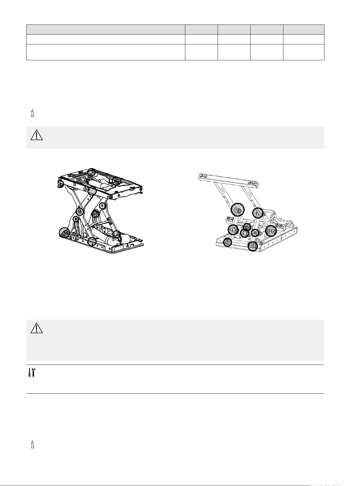
4.3Lubrication
Tomaintainthesmoothoperationofthepowerpositioningsystem(PPS),periodicallubricationofthemainpivotpointsis
recommended.MotionConceptsseatingsystemsarepre-lubricatedatthefactory,howeveroccasionallubricationusinga
generalpurposeoilwillhelptomaintainoptimalperformanceofyourseatingsystem.
Avoidtheuseofheavygreaseorhighviscositylubricantsasthiscancauseabuild-upofdirtandcontaminates
whichcouldreduceoverallperformance.
CAUTION!
Riskofinjuryanddamagetowheelchair
–Turnoffwheelchairpriortocleaningandlubricating.
PivotPointLubrication
Fig.4-1Liftermodule
Fig.4-2Tiltmodule
1.Tilt/Lifttheseatingsystem.
2.Useacleanragtowipeawayanydirt,residuearoundpivotsandalongslidechannels.
3.Lubricatemainpivotpoints(asindicated)onthemoduleperiodicallyusingageneralpurposeoil.
4.4UpdatingACS2Software
ThefollowingisvalidonlyforACS2software.YoundLiNXprogrammingparametersintheLiNXservicemanual.
WARNING!
Anychangestothedriveprogramcanaffectthedrivingcharacteristicsandthetippingstabilityofthe
mobilitydevice.
–ChangestothedriveprogrammayonlybecarriedoutbytrainedInvacareproviders.
–Invacarecanonlygiveawarrantyforsafemobilitydevicedrivingbehaviour—especiallythetippingstability
—forunalteredstandarddriveprograms.
•Dynamic®Wizardsoftware
•UsermanualofWizardsoftware
•Furtherrequirements,suchasaminimumsystemcongurationforthePCusedforprogramming,required
programmingcablesetc.,canbetakenfromtheWizardsoftwareusermanual.
ThedriveprogramsformobilitydevicesarecontinuallybeingfurtherdevelopedandimprovedbyInvacare.Forthisreason,
youshouldalwayscheckwhetherthedriveprogramversionnumberisup-to-datewhencarryingoutanyrepairsor
regularmaintenance.
Ifanewerversionisavailable,thedriveprogramshouldbeupdated.Theprocedureforupdatingthedriveprogram
isdescribedintheWizardsoftwareoperatingmanual.
Theelectronicsystemissuppliedwithastandarddriveprogram.Ifthedriveprogramhasbeencustomised,you
havetoperformthiscustomisationagain,afterinstallingthenewdriveprogram.
1586649-F25
Invacare®UltraLowMaxxbyMotionConcepts
Whenapoweredadjustmentoptionisretrotted,suchaspoweredlegrests,thenthisoptionneedstobeactivated
inthedrivingprogramaswellifyouhaveanACS2remote.Formoreinformation,refertotheusermanualofthe
Wizardsoftwareandtheinstallationinstructionsfortheelectronicmodules
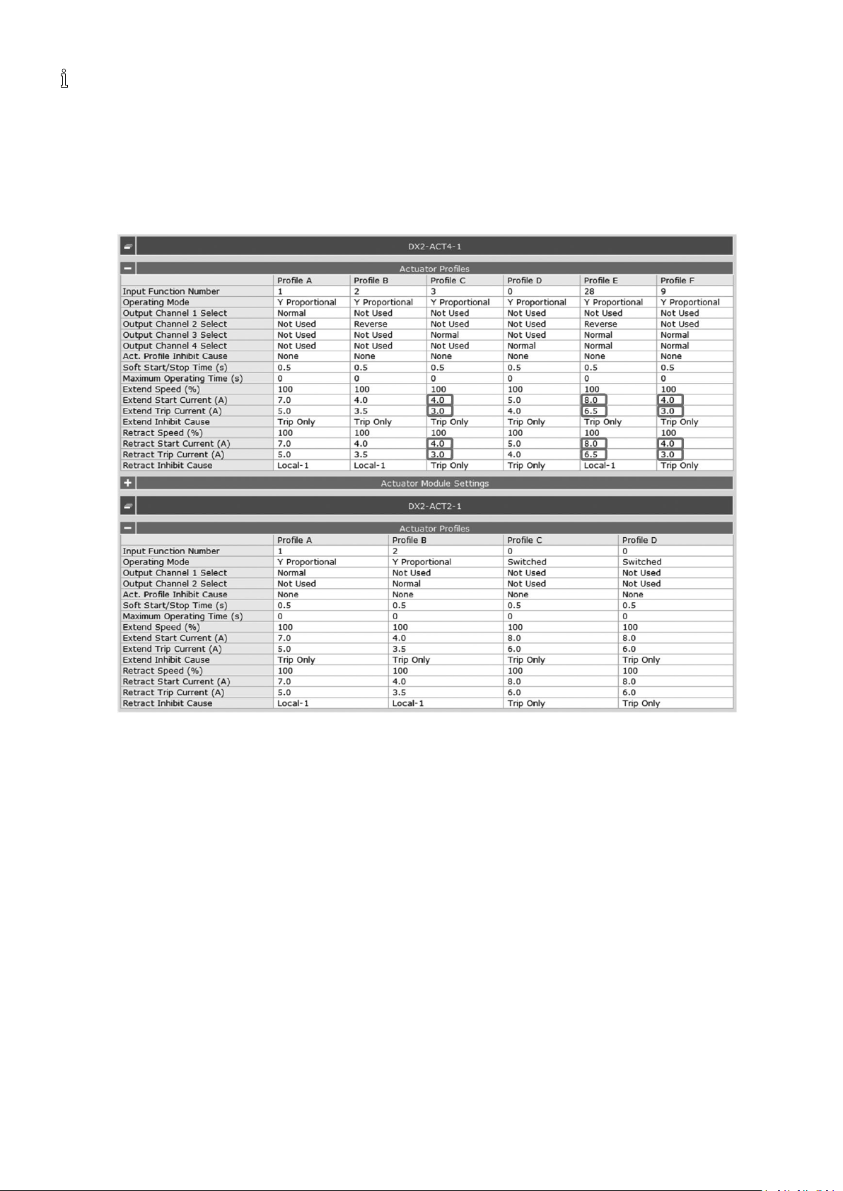
SettingsforLNXandPoweredPivotPlusLegrests
TheLNXandpoweredPivotPluslegrestsuselowercurrentsthanotherpoweredlegrests.Ifyouusestockprograms
forreprogrammingthepowerwheelchairwithUltraLowMaxxseatandpoweredlegrest,thefollowingvaluesonthe
currentsettingmustbeset.
•Foroptiontilt/reclineandLNXlegrest:
261586649-F

•Foroptionlifterwithtilt/reclineandLNXlegrest:
Service
•Foroptiontilt/reclineandPivotPluslegrest:
1586649-F
27
Invacare®UltraLowMaxxbyMotionConcepts
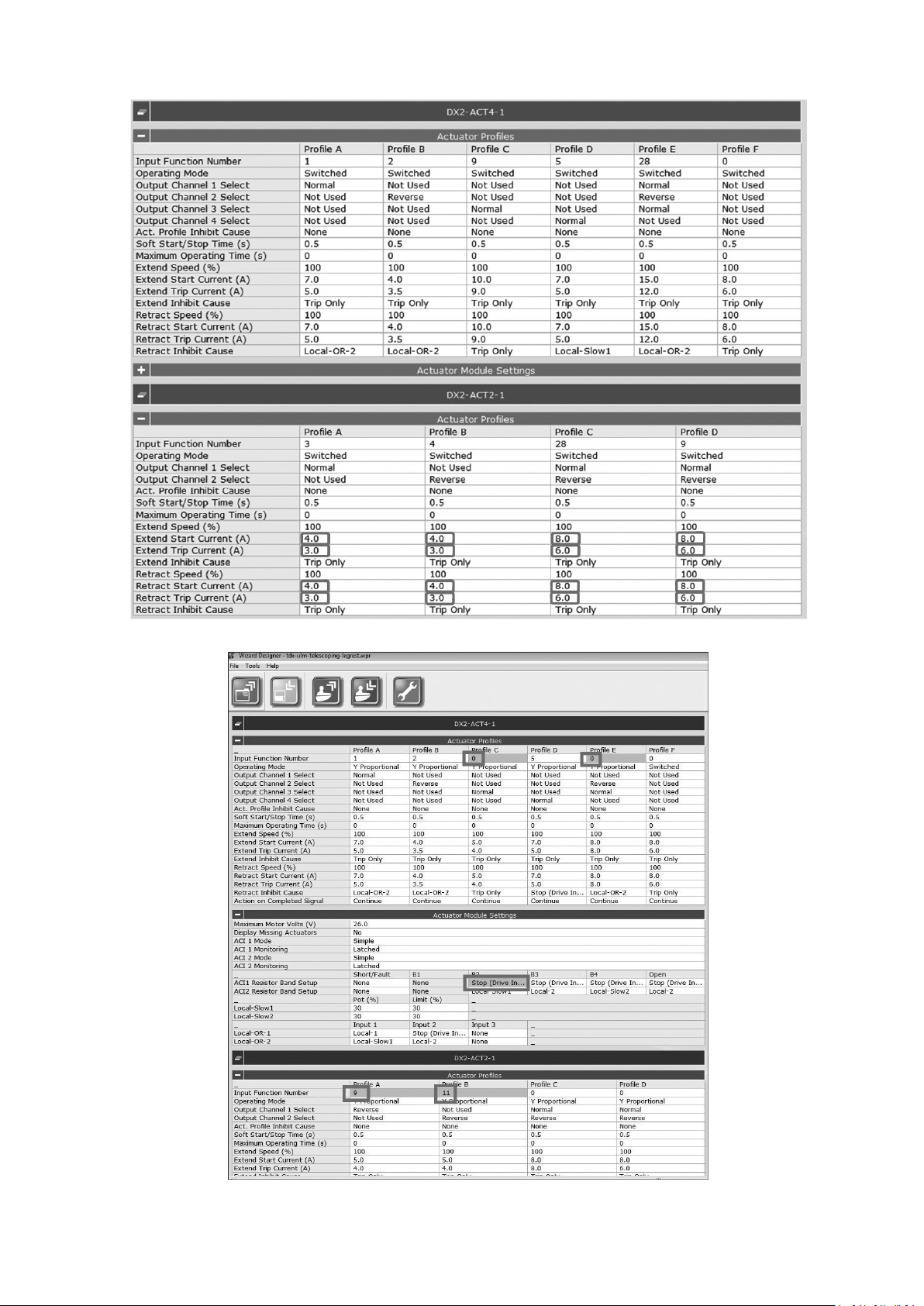
•Foroptionlifterwithtilt/reclineandPivotPluslegrest:
•ForLNXlegrestwithtelescopingfootboard:
281586649-F
5SettingsandAdjustments
5.1Measuringcorrectly
Whenmeasuringdimensionssuchastheseatdepth,you
needtomeasurefromdenedpointstoensurethatyou
getcorrectvalues.
Notethatmeasuredvaluesmayvaryupto±10
mm.
Measuringseatdepth
SettingsandAdjustments
Fig.5-1
–Ensurebaseisonalevelsurfacewhen
adjustinglimits.
Aftertheanglehasbeenset,ensurethedrivelockoutis
tested.Readjustmentmayberequired.
Measuringseatwidth
Measuringbackrestheight
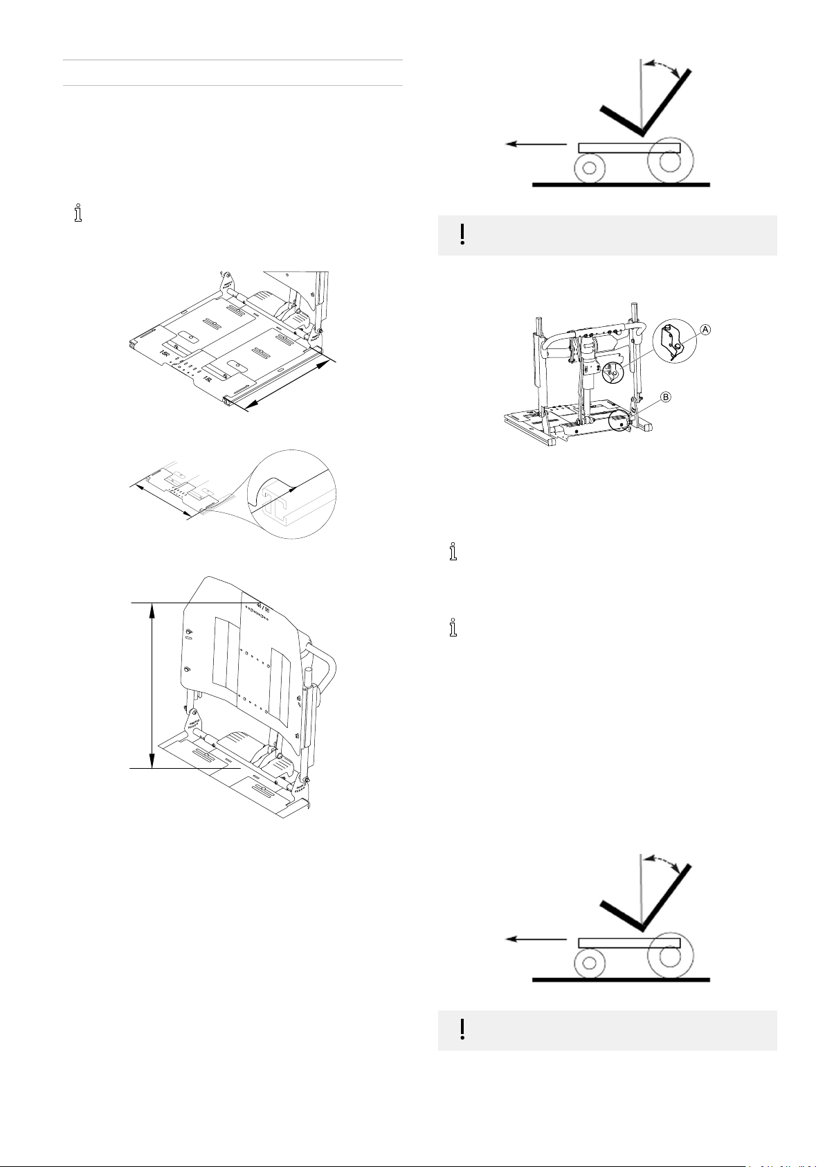
5.2SettingDriveLockoutandLimit Switches
Fig.5-2
TheDLOswitchAistypicallymountedtothesideofthe
actuatormoduleonthebackrestplate.TheadditionalDLO
switchontheStorm
4
Bistypicallymountedunderthe
shroudonthemostrearwardpointoftheseatplate.
IftheDLOisactivatedwhileadjustingtheswitch
angle,youmustactivatethetiltorreclineonce
tobeabletore-testtheDLO.Otherwise,theDLO
remainsactivated,regardlessoftheswitchangle.
TheDLOlimitshouldalwaysbesettotheangle
thatbestmeetstheindividualneedsoftheuser
andoverallstabilityofthewheelchair .However ,
theDLOangleshouldnotexceedthemaximum60°
(TDXSP2)/50°(Storm
4
)backrestangle.
SettingtheDriveLockoutforTilt/ReclineSystems—LiNX
Systems
AllPPSaresuppliedwithadrivelockout(DLO)switch.This
preventsthedrivemotorsfromoperatingifthecombined
tilt/reclineangleispositionedbeyondapre-determined
angle.Themaximumdrivelockoutangleis60°(TDX
SP2)/50°(Storm
OntheStorm
4
)fromthevertical(seediagrambelow).
4
,anadditionalswitchactivatestheDLOif
thetiltangleexceeds25°.
SettingtheDriveLockoutforTilt/ReclineSystems—ACS2
Systems
AllPPSaresuppliedwithadrivelockout(DLO)switch.This
preventsthedrivemotorsfromoperatingifthecombined
tilt/reclineangleispositionedbeyondapre-determined
angle.Themaximumdrivelockoutangleis60°(TDX
SP2)/50°(Storm
OntheStorm
4
)fromthevertical(seediagrambelow).
4
,anadditionalswitchactivatestheDLOif
thetiltangleexceeds25°.
–Ensurebaseisonalevelsurfacewhen
adjustinglimits.
Fig.5-3
TheDLOswitchisoneofseveralanglesensorsinstalledin
theactuatormodule.TheDLOangleissetviatheLockout
1586649-F29
Invacare®UltraLowMaxxbyMotionConcepts
Triggerparameterinthewheelchairsetup.SeeModifying
SeatingParameterswithPCtooloriOstoolintheLiNX
servicemanual.
Aftertheanglehasbeenset,ensurethedrivelockoutis
tested.Readjustmentmayberequired.
TheDLOlimitshouldalwaysbesettotheangle
thatbestmeetstheindividualneedsoftheuser
andoverallstabilityofthewheelchair .However ,
theDLOangleshouldnotexceedthemaximum60°
(TDXSP2)/50°(Storm
4
)backrestangle.
Fig.5-6
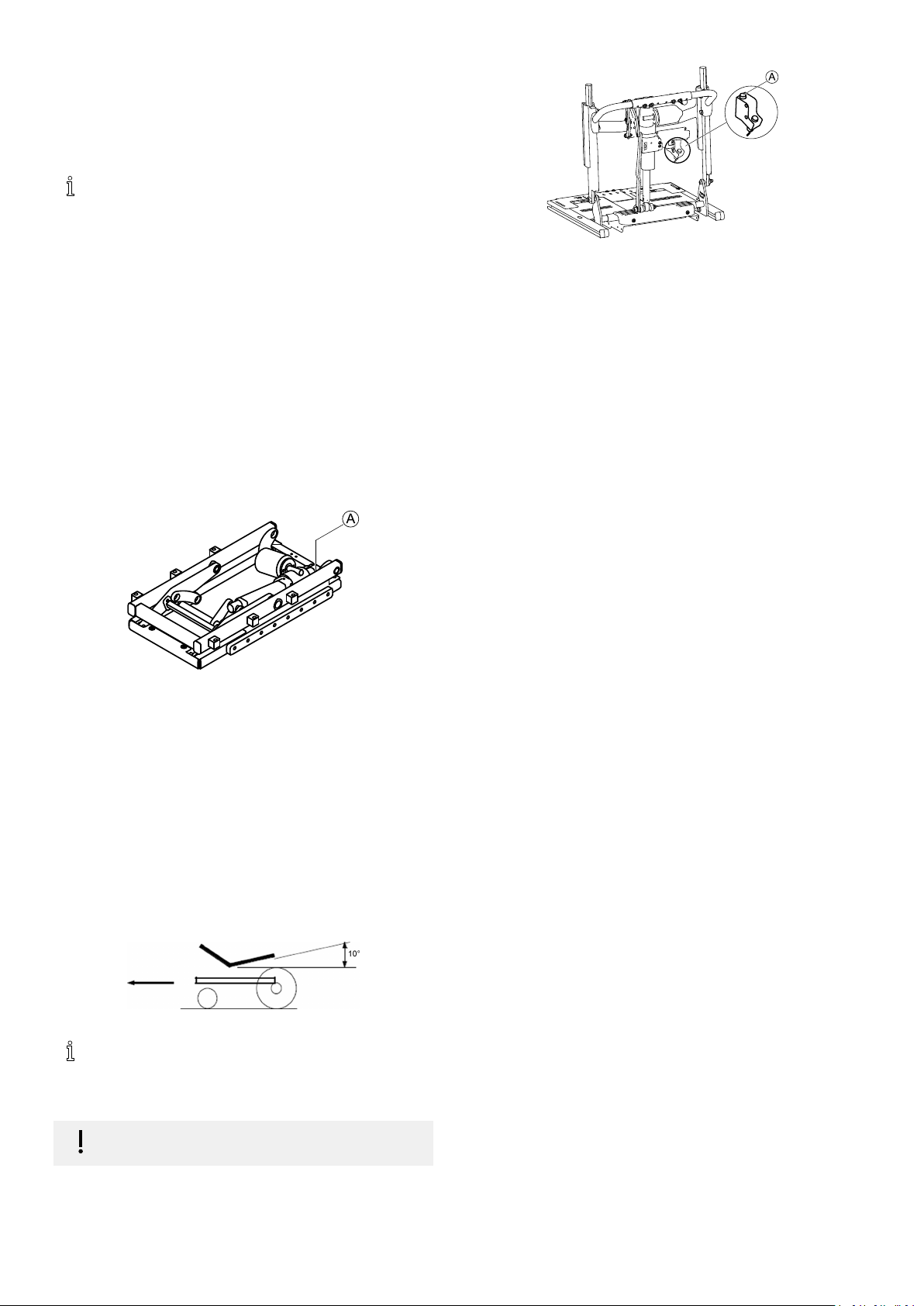
SpeedReductionMicroswitchforPowerElevatingSeats
AllPPSwithpowerelevatingseats(PES)arettedwith
amicroswitchforthespeedreduction.Thismicroswitch
reducesthespeedby30%whentheseatactuatoris
elevatedbeyondarecommended100mm(4in,TDX
SP2)/10mm(3/8in,Storm
4
)limit,measuredfromthe
home(lowest)position.Thespeedreductionmicroswitch
functionsasa‘normallyclosed’circuit.Thisprovidesfail
safeoperation.Assoonastheseatiselevatedoverthe
100mm(4in,TDXSP2)/10mm(3/8in,Storm
4
)limit,the
switchisopenedandthespeedreductionisengaged.
Ensurethespeedreductionmicroswitchistestedafter
installation.Readjustmentsmayberequired.
Fig.5-4
Thespeedreductionmicroswitchislocatedinthelower
leftcornerattherearoftheliftermoduleA.
SettingMax.BackAngleLimitSwitch
AllPPSareavailablewithamax.backanglelimitfunction.
Thisfunctionpreventsthebackanglefromextending
beyondapre-setangle.Thecorrectmax.backanglelimit
differsforeachinstallation.Thelimitswitchshouldbeset
sothatwithanycombinationoftiltandrecline,thereis
nochanceofinterferencebetweenthebackrestofthePPS
andthewheelchairbaseoranyaccessorieslocatedatthe
back.Thereclineangleshouldneverextendbeyondthe
recommendedminimumgapof10°fromthehorizontal
(seegraphicbelow).
Fig.5-5
Themax.backlimitswitchwillneedtobesetto
bestmeettheneedsoftheuser.However ,the
reclineangleshouldnotbepermittedtoextend
beyondtherecommendedminimumgapof10°.
–Ensurebaseisonalevelsurfacewhen
adjustinglimits.
Afterthebackanglehasbeenset,ensurethemax.back
anglelimitistested.Readjustmentsmayberequired.
Foratilt/reclineseatingsystem,theswitchAistypically
mountedtothesideoftheactuatormodulemounting
bracketonthebackofthesystem.
5.3Centerofgravity(CG)adjustments (forwardandaft)
TheUltraLowMaxxpowerpositioningsystemmaybe
adjustedintheforwardandaftdirectionwhenbeing
mountedontoapowerbase.Severalfactorsmustbe
consideredwhendeterminingthecorrectpositionforthe
user,includingtheclientsweightdistributionandbody
type.Itisveryimportanttoensureadequatestabilityis
maintainedduringdriving,andinthevariouspowered
seatingpositions.Whendeterminingasuitablesystemfor
aclient,itisequallyimportanttoensurethattheuser’s
weightdoesnotexceed(thelesserof)thecalculated
wheelchairweightcapacityorthedesignatedpower
positioningsystem(PPS)weightcapacity.
Importantinformation(fordealersandusers)
TheUltraLowMaxxpowerpositioningsystemisdesigned
toaccommodateawiderangeofuserneeds.Onlythe
dealerandthehealthcareprofessionalcanensurethat
thesystemmeetstheuser’ sindividualrequirements.Itis
thedealer’sresponsibilitytoensurethatthewheelchair
andthepowerpositioningsystemaresetupproperlyand
safelyfortheenduser’sspecicneeds.
Stability
Bychangingtheseatingposition(tilting,reclining,or
elevating),theuserischangingthestabilitycharacteristics
ofthewheelchair .Itisveryimportantthatthesystemis
setupsothatitisstableinallseatingpositions.When
evaluatingstability,rememberthefollowing:
•TheUltraLowMaxxsystemcanbemountedontothe
powerbaseinvariousforeandaftpositions.Make
certainthatthepositionselectedprovidestheuser
withmaximumstabilityoverthefullrangeofseating
positions.
•Considerallpersonalgearandaccessories(backpacks,
ventsystems,extrabatteries,etc.)thatwillbe
carriedonthewheelchair .Forexample,aloaded
backpack,attachedtothebackoftheseatingsystem,
cansignicantlyreducetherearwardstabilityofthe
wheelchair.Considerthebackrestbeingused.For
example,arecessedbackrestcanshifttheuser’s
centerofgravitybackandsignicantlyreducethe
rearwardstabilityofthewheelchair .Conversely ,a
thickbackcushionwillshifttheuserforwardand
reducethewheelchairsforwardstability.
•Considertheseatcushionbeingused.Athickseat
cushionwillraisetheuser’scenterofgravityand
reducethewheelchair’sstabilityinalldirections.
301586649-F
 Loading...