

Invacare MK5 EX, MK5 TT-EX Service Manual

Service Manual
MK
™
EX
™
5
™
MK
TT-EX
5
Electronics
and
™
DEALER: Keep this manual. The
procedures in this manual MUST be
performed by a qualified technician.
For more information regarding Invacare
products, parts, and services, please visit
www.invacare.com

WARNING
A QUALIFIED TECHNICIAN MUST PERFORM THE INITIAL SET UP
OF THIS WHEELCHAIR. ALSO, A QUALIFIED TECHNICIAN MUST
PERFORM ALL PROCEDURES IN THE SERVICE MANUAL.
WHEELCHAIR USERS: DO NOT SERVICE OR OPERATE THIS
EQUIPMENT WITHOUT FIRST READING AND UNDERSTANDING
(1) THE OWNER’S OPERATOR AND MAINTENANCE MANUAL
AND (2) THE SEATING SYSTEM’S MANUAL (IF APPLICABLE). IF
YOU ARE UNABLE TO UNDERSTAND THE WARNINGS,
CAUTIONS, AND INSTRUCTIONS, CONTACT INVACARE
TECHNICAL SUPPORT BEFORE ATTEMPTING TO SERVICE OR
OPERATE THIS EQUIPMENT - OTHERWISE INJURY OR DAMAGE
MAY RESULT.
DEALERS AND QUALIFIED TECHNICIANS: DO NOT SERVICE OR
OPERATE THIS EQUIPMENT WITHOUT FIRST READING AND
UNDERSTANDING (1) THE OWNER’S OPERATOR AND
MAINTENANCE MANUAL, (2) THE SERVICE MANUAL (IF
APPLICABLE) AND (3) THE SEATING SYSTEM’S MANUAL (IF
APPLICABLE). IF YOU ARE UNABLE TO UNDERSTAND THE
WARNINGS, CAUTIONS AND INSTRUCTIONS, CONTACT
INVACARE TECHNICAL SUPPORT BEFORE ATTEMPTING TO
SERVICE OR OPERATE THIS EQUIPMENT - OTHERWISE, INJURY
OR DAMAGE MAY RESULT.
NOTE: This manual is also available in French Canadian (Part Number 1123834).
NOTE: Updated versions of this manual are available on www.invacare.com.
™
MK
EX™ and MK
5
™
TT-EX™ Electronics 2 Part No 1114808
5

TABLE OF CONTENTS
TABLE OF CONTENTS
SPECIAL NOTES ................................................................................ 7
SECTION 1—EMI INFORMATION ....................................................... 8
SECTION 2—TROUBLESHOOTING .................................................... 10
All Power Wheelchairs ...........................................................................................................................10
Wheelchairs With Powered Seating Systems....................................................................................11
Formula™TRE only.............................................................................................................................12
SECTION 3—JOYSTICK DESCRIPTIONS ............................................. 14
Joystick Overview.....................................................................................................................................14
DPJ Joystick Switches and Indicators ...................................................................................................14
Power/Drive Select Toggle Switch ..................................................................................................14
Selecting the Drive Mode .............................................................................................................14
Turning the Wheelchair Off ........................................................................................................14
Speed Control Knob ...........................................................................................................................15
Mode (On/Off) Switch........................................................................................................................15
Battery Gauge Display (BGD)...........................................................................................................15
MPJ Joystick Switches and Indicators...................................................................................................15
Power/Drive Select Toggle Switch ..................................................................................................16
Selecting the Drive Mode .............................................................................................................16
Turning the Wheelchair Off ........................................................................................................16
Speed Control Knob ...........................................................................................................................16
LCD Display ..........................................................................................................................................16
Remote On/Off Input..........................................................................................................................17
SECTION 4—REMOTE PROGRAMMER .............................................. 18
Overview....................................................................................................................................................18
Remote Programmer Terminology ......................................................................................................18
Function..................................................................................................................................................18
Value .......................................................................................................................................................19
Standard Program (Preset Programs) .............................................................................................19
User Memory Values...........................................................................................................................19
Description Of Remote Programmer Keys .......................................................................................19
SECTION 5—PERFORMANCE ADJUSTMENTS .................................... 20
Speed and Response Screen ..................................................................................................................20
Advanced Menu.........................................................................................................................................20
Performance Menu...................................................................................................................................20
Making Performance Adjustments........................................................................................................21
Performance Menu Description............................................................................................................24
SECTION 6—STANDARD VALUE SETTINGS ...................................... 32
Standard Value Settings...........................................................................................................................32
Part No 3 Manual Title

TABLE OF CONTENTS
TABLE OF CONTENTS
SECTION 7—CALIBRATION OF THE CONTROL MODULE ................... 33
When to Calibrate the Control Module.............................................................................................33
What Functions Can Be Calibrated .....................................................................................................33
Calibrating the Control Module............................................................................................................33
SECTION 8—CURRENT STATUS DISPLAY ......................................... 37
SECTION 9—DIAGNOSTIC CODES .................................................... 38
What Are Diagnostics Codes? ..............................................................................................................38
MK5 EX Controller Diagnostic Codes ...............................................................................................38
MK5 TT-EX Controller Diagnostic Codes ........................................................................................39
SECTION 10—OPTIONS ................................................................... 42
Display Unit................................................................................................................................................42
Drive Select and On/Off Switch.......................................................................................................42
Selecting the Drive Mode .............................................................................................................42
LCD Display ..........................................................................................................................................43
Remote On/Off ....................................................................................................................................43
Special Purpose Indicators .................................................................................................................43
MK5 PSR/PSF Joysticks............................................................................................................................44
Joystick Overview................................................................................................................................44
Power/Drive Select Toggle Switch ..................................................................................................45
Selecting the Drive Mode .............................................................................................................46
Turning the Wheelchair Off ........................................................................................................46
Speed Control Knob ...........................................................................................................................46
Battery Gauge Display (BGD)...........................................................................................................46
Mode and Level Indicators.................................................................................................................46
1558M4 Compact Joystick......................................................................................................................47
1500M4 Rim Head Control ...................................................................................................................48
1812M4 Dual Proportional Joystick .....................................................................................................48
1554M5 or 1554M4 Sip & Puff Switch Input ......................................................................................49
Driver Control Input Connector.....................................................................................................49
Proportional Attendant Connector.................................................................................................50
Sip and Puff (Pneumatic Switch) Input.............................................................................................50
Mounting Precautions and Maintenance.........................................................................................50
Selecting the Driver Input Type .......................................................................................................50
Calibrating the Sip & Puff Pressures ................................................................................................51
PACM5 Proportional Attendant Control...........................................................................................52
Override and Speed Control Knob.................................................................................................52
1552M Attendant Control .....................................................................................................................53
On/Off Toggle Switch .........................................................................................................................53
Four Directional Switch......................................................................................................................53
Manual Title 4 Part No

TABLE OF CONTENTS
TABLE OF CONTENTS
1556m Heavy Duty Joystick...................................................................................................................53
Using the Heavy Duty Joystick..........................................................................................................54
AUX12 Eight Output Electronic Communications Module ...........................................................54
AUX34 Ten Output Electronic Communications Module.............................................................55
ECU1 and ECU2 .......................................................................................................................................55
ECU3 and ECU4 .......................................................................................................................................55
Connector Description...........................................................................................................................55
MK5 Tilt, Recline and Elevate Control Module (TRECM)..............................................................56
Programming the TRECM..................................................................................................................57
TRECM Performance Adjust Menu Description ....................................................................57
TRECM Standard Programs Menu Description ......................................................................58
TRECM Actuator Selection Menu Description .......................................................................58
TRECM Current Status Menu Description ..............................................................................59
MK5 Tilt and Recline Control Module (TRCM) ...............................................................................60
Programming the TRCM ....................................................................................................................60
TRCM Performance Adjust Menu Description .......................................................................61
TRCM Standard Programs Menu Description ........................................................................62
TRCM Actuator Selection Menu Description .........................................................................63
TRCM Current Status Menu Description ................................................................................63
MK5 Two Actuator Controller (TAC) ...............................................................................................64
Programming the TAC .......................................................................................................................65
TAC System Type Menu Description .......................................................................................66
TAC Performance Adjust Menu Description ..........................................................................66
TAC Actuator Selection Menu Description ............................................................................67
TAC Current Status Menu Description ...................................................................................67
MK5 Single Actuator Control (SAC)...................................................................................................67
Lockout ..................................................................................................................................................68
Slow.........................................................................................................................................................68
SECTION 11—CALIBRATING POTENTIOMETERS .............................. 69
Preparing to Calibrate Potentiometers...............................................................................................69
Potentiometer Calibration for 2GTR Systems..................................................................................69
Tilt Angle Potentiometer Calibration .............................................................................................69
Recline Angle Potentiometer Calibration ......................................................................................70
Potentiometer Calibration for 2GT Systems.....................................................................................71
Tilt Angle Potentiometer Calibration .............................................................................................71
Potentiometer Calibration for 2GR Systems.....................................................................................72
Recline Angle Potentiometer Calibration ......................................................................................72
SECTION 12—CONNECTOR DESCRIPTIONS ...................................... 73
Driver Control Input Connector (1554M4 or 1554M5) ................................................................73
Part No 5 Manual Title

Environmental Control Outputs - ECU 1, 2, 3 and 4......................................................................73
Emergency Stop/Reset Switch ...............................................................................................................74
Emergency Stop/Reset Input..................................................................................................................74
15-pin D-Subminiature on Control Module.......................................................................................75
5-Pin Connector on Control Module..................................................................................................75
Battery Connector - Anderson SB50 ..................................................................................................75
MI and M2 Motor Connectors..............................................................................................................75
4-Pin (MK5 EX) ....................................................................................................................................75
13-Pin D-Sub (MK5 TT EX)...............................................................................................................76
5-Pin Connector on Control Module..................................................................................................76
PTO/Charge Input (MK5 EX)................................................................................................................76
Remote On/Off Input On MPJ or Display unit..................................................................................76
SECTION 13—CURRENT ROLLBACK ................................................ 77
What Is Current Rollback?.....................................................................................................................77
What Increases the Likelihood of Current Rollback?......................................................................77
Weight....................................................................................................................................................77
Rolling Resistance ................................................................................................................................77
Terrain Angle ........................................................................................................................................77
Speed.......................................................................................................................................................77
How to Solve It? .......................................................................................................................................78
Electronic Adjustments.......................................................................................................................78
Drive Motors ........................................................................................................................................78
Common Mistakes ...................................................................................................................................78
SECTION 14—APPENDIX ................................................................ 79
Special Purpose Indicator Description for LCD Display.................................................................79
LIMITED WARRANTY ..................................................................... 80
Manual Title 6 Part No

SPECIAL NOTES
SPECIAL NOTES
WARNING/CAUTION notices as used in this manual apply to hazards or unsafe
practices which could result in personal injury or property damage.
NOTICE
THE INFORMATION CONTAINED IN THIS DOCUMENT IS SUBJECT TO
CHANGE WITHOUT NOTICE.
REPAIR OR SERVICE WARNING
Setup of the Electronic Controller is to be performed ONLY by individuals certified
by Invacare. The adjustments of the controller may affect other activities of the
wheelchair. Damage to the equipment could occur under these circumstances. If
uncertified individuals perform any work on these units, the warranty is void.
OPERATION WARNING
Performance adjustments should only be made by professionals of the health care
field or persons fully conversant with this process and the driver's capabilities. Incorrect settings could cause injury to the driver, bystanders, damage to the chair and
surrounding property. After the wheelchair has been setup, check to make sure that
the wheelchair performs to the specifications entered in the setup procedure. If the
wheelchair does NOT perform to specifications, turn the wheelchair OFF immediately and re-enter setup specifications. Repeat this procedure until the wheelchair
performs to specifications.
Part No 1114808 7 MK
™
EX™ and MK
5
™
TT-EX™ Electronics
5

SECTION 1—EMI INFORMATION
SECTION 1—EMI INFORMATION
WARNING
CAUTION: IT IS VERY IMPORTANT THAT YOU READ THIS INFORMATION
REGARDING THE POSSIBLE EFFECTS OF ELECTROMAGNETIC
INTERFERENCE ON YOUR POWERED WHEELCHAIR.
Electromagnetic Interference (EMI) From Radio Wave Sources
Powered wheelchairs and motorized scooters (in this text, both will be referred to
as powered wheelchairs) may be susceptible to electromagnetic interference (EMI),
which is interfering electromagnetic energy (EM) emitted from sources such as
radio stations, TV stations, amateur radio (HAM) transmitters, two way radios, and
cellular phones. The interference (from radio wave sources) can cause the powered
wheelchair to release its brakes, move by itself, or move in unintended directions. It
can also permanently damage the powered wheelchair's control system. The
intensity of the interfering EM energy can be measured in volts per meter (V/m).
Each powered wheelchair can resist EMI up to a certain intensity. This is called its
"immunity level." The higher the immunity level, the greater the protection. At this
time, current technology is capable of achieving at least a 20 V/m immunity level,
which would provide useful protection from the more common sources of radiated
EMI.
There are a number of sources of relatively intense electromagnetic fields in the
everyday environment. Some of these sources are obvious and easy to avoid.
Others are not apparent and exposure is unavoidable. However, we believe that by
following the warnings listed below, your risk to EMI will be minimized.
The sources of radiated EMI can be broadly classified into three types:
1) Hand-held Portable transceivers (transmitters-receivers with the antenna
mounted directly on the transmitting unit. Examples include: citizens band (CB)
radios, "walkie talkie", security, fire and police transceivers, cellular telephones,
and other personal communication devices).
NOTE: Some cellular telephones and similar devices transmit signals while they are ON,
even when not being used.
2) Medium-range mobile transceivers, such as those used in police cars, fire trucks,
ambulances and taxis. These usually have the antenna mounted on the outside of
the vehicle; and
3) Long-range transmitters and transceivers, such as commercial broadcast
transmitters (radio and TV broadcast antenna towers) and amateur (HAM)
radios.
NOTE: Other types of hand-held devices, such as cordless phones, laptop computers,
AM/FM radios, TV sets, CD players, cassette players, and small appliances, such as electric shavers and hair dryers, so far as we know, are not likely to cause EMI problems to
your powered wheelchair.
™
MK
EX™ and MK
5
™
TT-EX™ Electronics 8 Part No 1114808
5

SECTION 1—EMI INFORMATION
WARNING
Powered Wheelchair Electromagnetic Interference (EMI)
Because EM energy rapidly becomes more intense as one moves closer to the
transmitting antenna (source), the EM fields from hand-held radio wave sources
(transceivers) are of special concern. It is possible to unintentionally bring high
levels of EM energy very close to the powered wheelchair's control system while
using these devices. This can affect powered wheelchair movement and braking.
Therefore, the warnings listed below are recommended to prevent possible
interference with the control system of the powered wheelchair.
Electromagnetic interference (EMI) from sources such as radio and TV stations,
amateur radio (HAM) transmitters, two-way radios, and cellular phones can affect
powered wheelchairs and motorized scooters.
FOLLOWING THE WARNINGS LISTED BELOW SHOULD REDUCE THE
CHANCE OF UNINTENDED BRAKE RELEASE OR POWERED WHEELCHAIR
MOVEMENT WHICH COULD RESULT IN SERIOUS INJURY.
1) Do not operate hand-held transceivers (transmitters receivers), such as citizens
band (CB) radios, or turn ON personal communication devices, such as cellular
phones, while the powered wheelchair is turned ON;
2) Be aware of nearby transmitters, such as radio or TV stations, and try to avoid
coming close to them;
3) If unintended movement or brake release occurs, turn the powered wheelchair
OFF as soon as it is safe;
4) Be aware that adding accessories or components, or modifying the powered
wheelchair, may make it more susceptible to EMI (NOTE: There is no easy way
to evaluate their effect on the overall immunity of the powered wheelchair); and
5) Report all incidents of unintended movement or brake release to the powered
wheelchair manufacturer, and note whether there is a source of EMI nearby.
Important Information
1) 20 volts per meter (V/m) is a generally achievable and useful immunity level
against EMI (as of May 1994) (the higher the level, the greater the protection);
2) The immunity level of the product is unknown.
Modification of any kind to the electronics of this wheelchair as manufactured by
Invacare may adversely affect the RFI immunity levels.
Part No 1114808 9 MK
™
EX™ and MK
5
™
TT-EX™ Electronics
5
SECTION 2—TROUBLESHOOTING
SECTION 2—TROUBLESHOOTING
All Power Wheelchairs
SYMPTOM PROBABLE CAUSE SOLUTIONS
Error Code:
E9 or E10 - MPJ joystick
3 flashes - DPJ joystick
Error Code:
E28 - MPJ joystick
5 flashes - DPJ joystick
Error Code:
E14 - MPJ joystick
5 flashes - DPJ joystick
Joystick erratic or does
not respond as desired.
Wheelchair veers to the
left or right when driving
on level surface.
No LED’s on joystick. Joystick connection to controller
Corroded wiring or
connections.
Wheelchair does not
respond to commands.
Power indicator off - even
after recharging.
Wheelchair slows or
stops while driving AND
one (1) of the following
occurs:
DPJ Joystick - ORANGE
LED flashes
Motor lock levers disengaged. Engage motor lock levers. Refer to the wheelchair
Owner’s Manual for more information.
Bad motor connection. Check all motor connections.
Bad brake coil. Ohm out motors. Check brushes and replace if
necessary. Replace motors if high reading is present.
Normal reading is 0-5 Ohms (4 Pole only). Calibrate
GB motors. Refer to wheelchair Service Manual.
Battery charger connected. Unplug battery charger from the wheelchair. Refer
to the wheelchair Owner’s Manual for information
about the battery charger.
Batteries need to be charged. Charge batteries. Refer to the wheelchair Owner’s
Manual for charging instructions.
Damaged motor coupling. Contact Dealer/Invacare for Service.
Electrical malfunction. Contact Dealer/Invacare for Service.
Controller programmed
improperly.
Joystick needs to be calibrated. Calibrate joystick with programmer. If this does not
unplugged or damaged.
Possible water, salt, or urine
damage.
Poor battery terminal
connection.
Bad joystick connection. Check all joystick connections. Refer to wheelchair
Bad wiring harness connection
or blown fuse.
Electrical malfunction. Contact Dealer/Invacare for Service.
Current rollback. Wheelchair
has been driving under a heavy
load for an extended period of
time.
Contact Dealer/Invacare to have controller
reprogrammed.
work, replace joystick. Refer to Joystick Throw
page 25 for calibration information.
Check all joystick connections. Refer to wheelchair
Owner’s Manual. If damage is found, replace joystick.
Replace wiring harness. Refer to wheelchair
Owner’s Manual.
Have clean terminals. Refer to wheelchair Owner’s
Manual.
Owner’s Manual.
Replace wiring harness. Refer to wheelchair
Owner’s Manual.
Adjust driving parameters to match driving
environment.
Allow time for the electronics to cool down (Light
Duty Use).
on
MPJ Joystick “HOT” or “SLOW” is
displayed
™
MK
EX™ and MK
5
™
TT-EX™ Electronics 10 Part No 1114808
5
SECTION 2—TROUBLESHOOTING
Wheelchairs With Powered Seating Systems
SYMPTOM PROBABLE CAUSE SOLUTIONS
Wheelchair Power ON but does
not drive.
Seating system not functioning or
working intermittently.
Error Code:
E28 - MPJ joystick
or
5 flashes - DPJ joystick
System tilted, reclined or
elevated beyond drive
lock-out angle (20°).
Return to neutral position (upright and completely
lowered). Refer to the seating system Owner’s
Manual for seating system operating instructions.
Use the programmer to check the Current Status
Menu, particularly the drive lock-out setting. Refer
to TRECM Current Status Menu Description
page 59.
To adjust drive lock-out angle, Refer to the Formula
TRE setup instructions, part number 1125061 for
drive lock-out adjustment instructions.
To turn drive lock-out on or off, refer to TRECM
Performance Adjust Menu Description on page 57.
Low batteries. Charge batteries. Refer to the seating system
Owner’s Manual.
Faulty electrical
Check all connections.
connection.
Blown fuse. Replace wiring harness. Refer to the seating system
Owner’s Manual.
Seat has been driven
under a heavy load for an
extended period of time.
Open Motor
connection/Motor locks
Allow time for the electronics to cool down (Light
Duty Use). Leave power on, and do not activate
powered seating functions for at least 3 minutes.
Check all motor connectors.
Make sure motor locks are engaged.
disengaged.
Malfunctioning seating
Replace seating system controller. Contact Invacare.
system controller
(TRECM, SAC-E, or ESC).
Bad user switch. Use the programmer to check the TRECM Current
Status Menu for switch status. Refer to TRECM
Current Status Menu Description on page 59.
System tilted, reclined or
elevated beyond drive
lock-out angle (20°).
Return to neutral position (upright and completely
lowered). Refer to seating system Owner’s Manual.
Use the programmer to check the Current Status
Menu, particularly the drive lock-out setting. Refer
to TRECM Current Status Menu Description
page 59.
To adjust drive lock-out angle, Refer to the Formula
TRE setup instructions, part number 1125061 for
drive lock-out adjustment instructions.
To turn drive lock-out on or off, refer to TRECM
Performance Adjust Menu Description on page 57.
Bad limit switch, limit
switch out of position or
limit switch missing.
Check limit switch setting. Refer to TRECM Current
Status Menu Description on page 59.
Refer to the Formula TRE setup instructions, part
number 1125061 for limit switch adjustment
instructions.
on
on
Part No 1114808 11 MK
™
EX™ and MK
5
™
TT-EX™ Electronics
5
SECTION 2—TROUBLESHOOTING
SYMPTOM PROBABLE CAUSE SOLUTIONS
Wheelchair slows or stops while
driving AND one (1) of the
following occurs:
DPJ Joystick - ORANGE LED
flashes
MPJ Joystick “SLOW” is displayed
Wheelchair drives at full speed
when seat is elevated.
Wheelchair will not drive when
seat is elevated.
Programmer does not work or
gives “communication error”
Elevating seat is elevated.
The elevating seat is
equipped with a speed
reduction safety
mechanism. While the
seat is in an elevated
position, the safety feature
slows the speed of the
wheelchair by 80%.
Faulty electrical
connection.
Malfunctioning seating
system controller
(TRECM, SAC-E, or ESC).
If not an Elevate Only
system, the seat may be
tilted or reclined beyond
the drive lock-out angle
(20°).
System tilted, reclined or
elevated beyond drive
lock-out angle (20°).
Return the seat to its lowest position. Refer to the
seating system Owner’s Manual.
Check all connectors.
Check for error codes. Refer to Options
on page 42
for the correct performance adjustment menu
descriptions. Replace seating system controller, if
necessary. Contact Invacare.
Return to neutral position (upright and completely
lowered). Refer to seating system Owner’s Manual.
Use the programmer to check the Current Status
Menu, particularly the drive lock-out setting. Refer
to TRECM Current Status Menu Description
on
page 59.
To adjust drive lock-out angle, Refer to the Formula
TRE setup instructions, part number 1125061 for
drive lock-out adjustment instructions.
To turn drive lock-out on or off, refer to TRECM
Performance Adjust Menu Description on page 57.
Formula™TRE only
SYMPTOM PROBABLE CAUSE SOLUTIONS
One or more functions do
not stop at the desired
position.
Incorrect switch response. Programming error or bad
™
MK
EX™ and MK
5
™
5
Limit switch not adjusted
properly.
switch.
TT-EX™ Electronics 12 Part No 1114808
Check limit switch setting. Refer to TRECM Current
Status Menu Description on page 59.
Refer to the Formula TRE setup instructions, part number
1125061 for limit switch adjustment instructions.
Use the programmer to verify TRECM programming. Save
the proper standard program to reset switch functions.
Refer to TRECM Standard Programs Menu Description
on
page 58.
SECTION 2—TROUBLESHOOTING
SYMPTOM PROBABLE CAUSE SOLUTIONS
Drive lock-out will not
engage.
Actuator speed too slow. Low battery voltage. Recharge batteries. Refer to the seating system Owner’s
Actuator speed too fast. Programming error. Check TRECM programming to confirm the speed setting
Functions respond to
switch command, but do
not operate through the
driver control.
Functions will only operate
in one direction
Programming error. Use the programmer to verify the drive lock-out setting in
the Current Status Menu. Refer to TRECM Current Status
Menu Description on page 59.
To adjust drive lock-out angle, Refer to the Formula TRE
setup instructions, part number 1125061 for drive
lock-out adjustment instructions.
To turn drive lock-out on or off, refer to TRECM
Performance Adjust Menu Description on page 57.
TRECM failure. Check all connections to TRECM.
Check limit switch setting. Refer to the Formula TRE
setup instructions, part number 1125061 for limit switch
adjustment instructions.
MK5 controller failure. Replace MK5 controller. Refer to the Service Manual for
the wheelchair.
Drive lock-out turned off
for that particular drive.
Turn on drive lock-out for the desired drive using your
programmer. Refer to TRECM Performance Adjust Menu
Description on page 57.
Limit switch not adjusted
properly.
Check limit switch setting. Refer to TRECM Current
Status Menu Description on page 59.
Refer to the Formula TRE setup instructions, part number
1125061 for limit switch adjustment instructions.
Manual.
Programming speed set
too low.
Check TRECM programming to confirm the speed setting
for the desired actuator. Refer to TRECM Performance
Adjust Menu Description on page 57.
for the desired actuator. Refer to TRECM Performance
Adjust Menu Description on page 57.
Programming error Check the Tilt/Recline setting and make sure it is adjusted
to the correct operating mode in the appropriate drive.
Incorrect or
malfunctioning driver
Refer to TILT/RECLINE
Replace driver control. Refer to wheelchair Service
Manual.
on page 30.
control
Improperly wired actuator
Check actuator wiring.
motor leads.
Limit switches not
adjusted properly.
Check limit switches for damage. If damaged replace them.
Contact Invacare.
Check limit switch setting. Refer to TRECM Current
Status Menu Description on page 59.
Refer to the Formula TRE setup instructions, part number
1125061 for limit switch adjustment instructions.
Part No 1114808 13 MK
™
EX™ and MK
5
™
TT-EX™ Electronics
5
SECTION 3—JOYSTICK DESCRIPTIONS
SECTION 3—JOYSTICK
DESCRIPTIONS
Joystick Overview
There are two (2) standard joysticks which make up the MK5 system. The two (2) joystick
types are the DPJ™ and MPJ™. The joysticks differ in user controls, switches, number of
programmable drives and performance adjustments. The joysticks provide proportional
drive control of speed and direction.
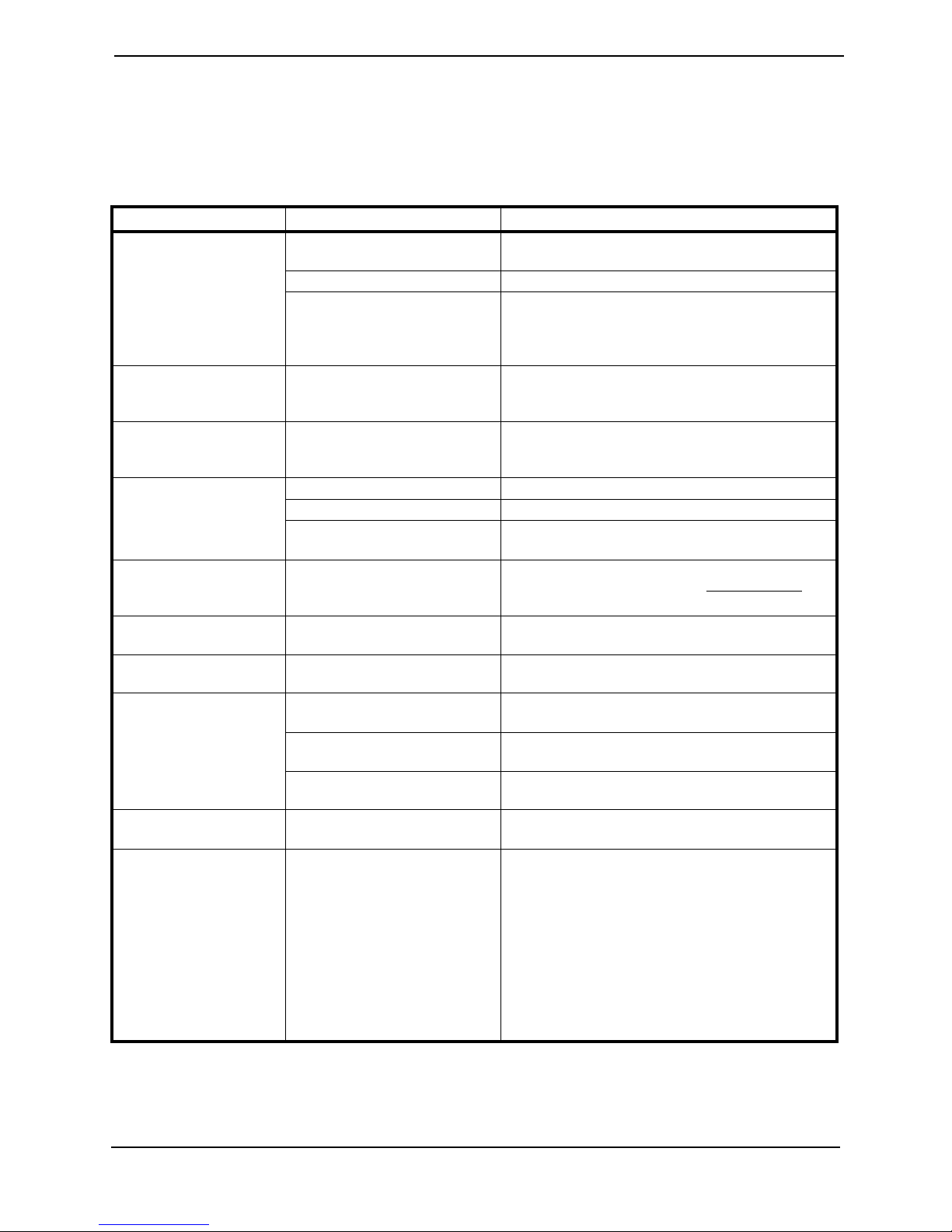
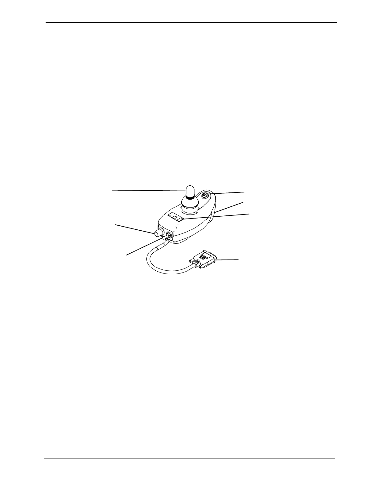
DPJ Joystick Switches and Indicators
NOTE: For this procedure, refer to FIGURE 3.1.
Joystick
Speed Control Knob
Power/Drive Select Toggle
Switch
Mode Switch
Charger/Programming Port
Battery Gauge Display
To Controller
FIGURE 3.1 DPJ Joystick Switches and Indicators
Power/Drive Select Toggle Switch
The three (3) position power/drive select toggle switch is located at the back of the joystick
housing. This switch allows the operator to select the type of operation or performance
which best suits a particular control need or situation and turn the wheelchair off. The
DRIVE 1 program uses performance values which are independent of those used for the
DRIVE 2 program. For example, an operator may have a control need for spasticity in the
morning and a very different need in the afternoon. DRIVE 1 can be programmed for
higher speeds and quicker response while DRIVE 2 can be programmed for slower
speeds and less responsiveness or vise versa.
Selecting the Drive Mode
1. To select DRIVE 1 mode, move the toggle UP.
2. To select DRIVE 2 mode, move the toggle to the MIDDLE position.
Turning the Wheelchair Off
1. To turn the wheelchair off, move the toggle DOWN.
™
MK
EX™ and MK
5
™
TT-EX™ Electronics 14 Part No 1114808
5
SECTION 3—JOYSTICK DESCRIPTIONS
Speed Control Knob
The speed control knob is located at the back of the joystick housing.
1. Turn the knob clockwise to increase the maximum speed of the wheelchair.
2. Turn the knob counterclockwise to decrease the maximum speed of the wheelchair.
Mode (On/Off) Switch
The mode (on/off) switch is a push button switch located at the front of the joystick. When
an optional actuator control [Single Actuator control, (SAC), Two Actuator Control (TAC)
or Tilt and Recline Control Module (TRCM)] is present, pushing the switch will change
the controller mode to control the optional actuators through the joystick. The mode
switch LED indicator will be ON. Push the switch again to return to normal joystick
driving. The mode switch LED indicator will be off.
Battery Gauge Display (BGD)
Located at the rear of the joystick housing, the BGD provides information on the
remaining charge in the batteries. At full charge, all six (6) segments of the bar graph are
lit. As the battery discharges, the farthest right (GREEN) segment will go out until only
the red bar is lit. At this level, the last red bar will start to flash on and off to indicate that
the user should charge the batteries as soon as possible.
The BGD also serves as a system diagnostic device when a fault is detected by the control
module. A specific number of flashes (up to eight (8) flashes) of the two (2) RED bars
separated by a pause will indicate the type of fault detected. A chart of the diagnostic
indications is given in Diagnostic Codes on page 38.
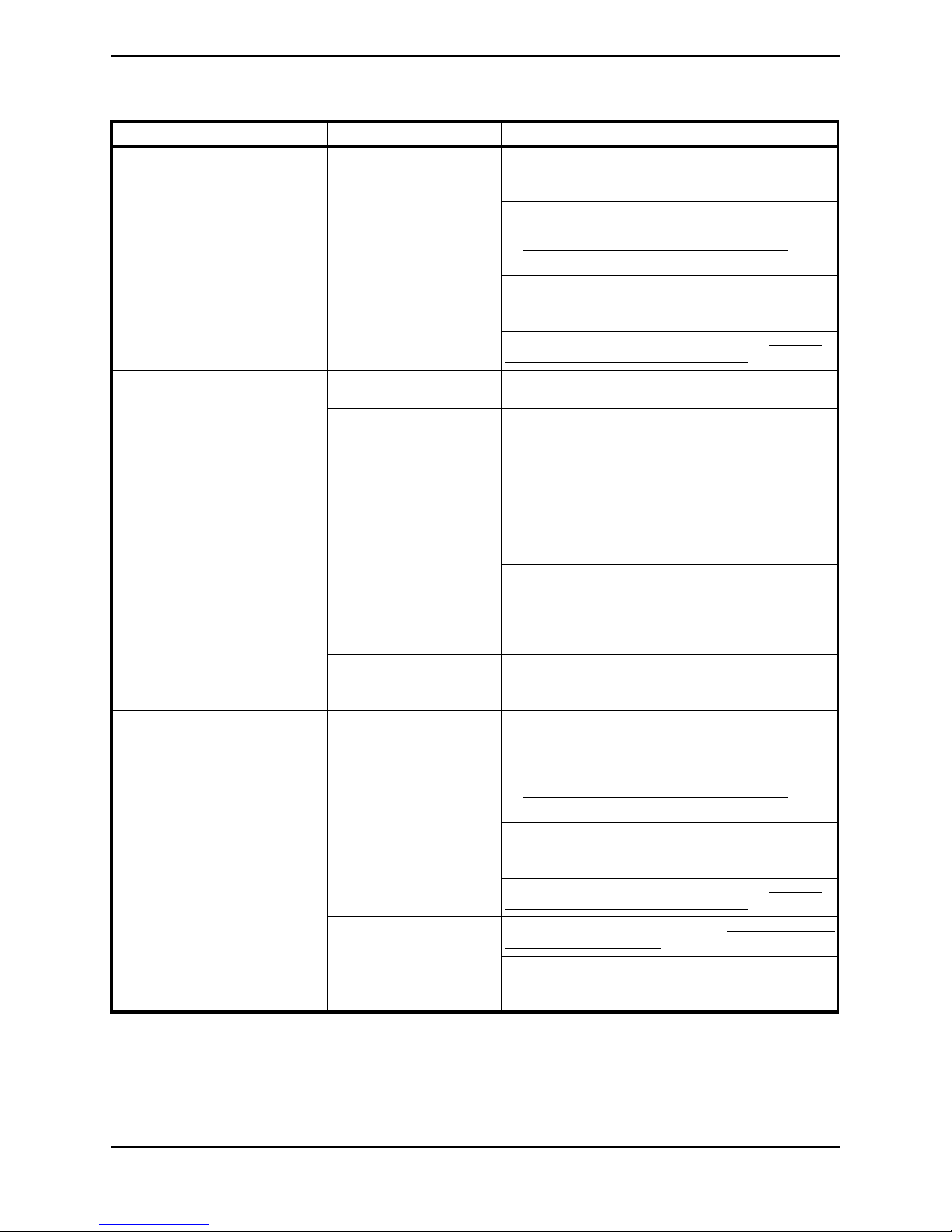
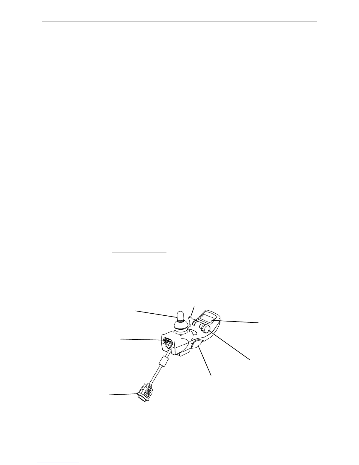
MPJ Joystick Switches and Indicators
NOTE: For this procedure, refer to FIGURE 3.2, unless otherwise indicated.
Power/Drive Select Toggle Switch
Joystick
LCD
Remote On/Off
Input
Speed Control Knob
Charger/Programming Input
To Controller
FIGURE 3.2 MPJ Joystick Switches and Indicators
Part No 1114808 15 MK
™
EX™ and MK
5
™
TT-EX™ Electronics
5

SECTION 3—JOYSTICK DESCRIPTIONS
Power/Drive Select Toggle Switch
A three (3) position power/drive select toggle switch is located on the side of the joystick
housing. The DRIVE SELECT position is momentary.
This switch allows the operator to select the type of operation or performance which best
suits a particular control need or situation. The DRIVE 1 program uses performance
values which are independent of those used for the DRIVE 2 or 3 or 4 program. As an
example, an operator may have a control need for spasticity in the morning and a very
different need in the afternoon. DRIVE 1 can be programmed for higher speeds and
quicker response while DRIVE 2 can be programmed for slower speeds and less
responsiveness. The remaining drive programs could also be used for indoor and outdoor
versions of DRIVE 1 and DRIVE 2. Finally, when a powered seating system is installed,
one of the remaining drives may be used to control the tilt, recline and/or elevate
functions.
Selecting the Drive Mode
1. Move the toggle UP and release. DRIVE 1 will appear on LCD.
2. Move the toggle UP and release again. DRIVE 2 will appear on LCD.
3. Move the toggle UP and release again. DRIVE 3 will appear on LCD.
4. Move the toggle UP and release again. DRIVE 4 will appear on LCD.
5. Move the toggle UP and release one more time to select DRIVE 1.
Turning the Wheelchair Off
1. Move the toggle BACK to turn the wheelchair off.
Speed Control Knob
The speed control knob is located on the side of the joystick housing.
1. Rotate the knob forward to increase the speed of the wheelchair to the programmed
max speed (FIGURE 3.2).
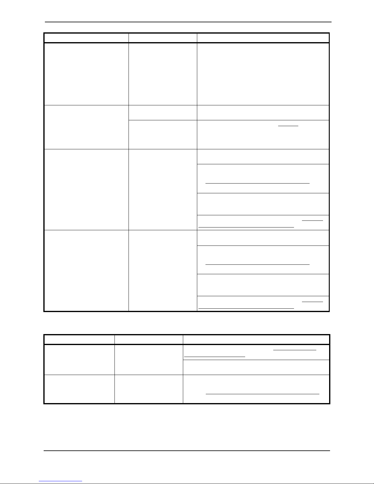
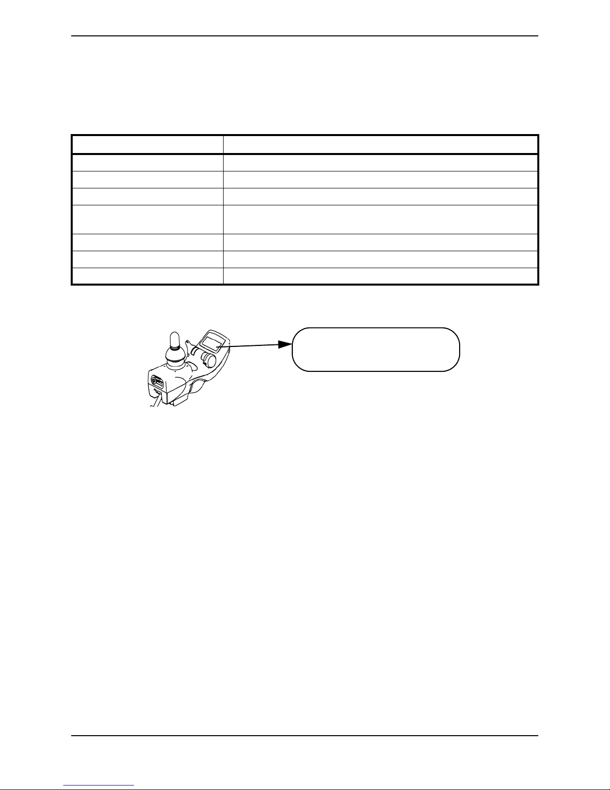
LCD Display
NOTE: For this procedure, refer to FIGURE 3.2 and FIGURE 3.3.
The LCD Display is located in front of the joystick and provides information on the status
of the wheelchair through a 2 line by 12 character length back lighted display. The LCD
display is readable in both bright sunlight and complete darkness (FIGURE 3.2).
During normal operation the active drive is displayed on the left half of the first line. The
left half of the second line displays the Battery Gauge Display (BGD). It provides
information on the remaining charge in the batteries. At full charge solid blocks fill in all
five segments between E (Empty) and F (Full). As the battery becomes discharged, the
furthest right segments will progressively disappear a half bar at a time until no segments
appear between E and F. At this level the word RECHARGE will appear on the second
line to indicate that the user should charge the batteries as soon as possible.
™
MK
EX™ and MK
5
™
TT-EX™ Electronics 16 Part No 1114808
5
SECTION 3—JOYSTICK DESCRIPTIONS
The right half of the display is the Information Center. The Information Center displays
current data on the wheelchair. FIGURE 3.3 shows the factory default odometer display.
The top line shows the unit of measured MI (miles). The second line is the value, 0000
(total miles driven).
The Information Center can display:
ITEM DESCRIPTION
Speedometer Current Wheelchair Speed - MPH/KMH
Trip Odometer Distance traveled since the wheelchair was last powered ON
Odometer Total Distance Traveled (Factory Default) - MI/KM
Trip Amp-Hour meter Battery Capacity consumed since the wheelchair was last powered ON -
AH
Battery Volts Current Battery Voltage - VOLT
Battery Current Battery current being used - AMP
Load Test Results Current battery condition based on a load test - BATT
If a fault is detected, the cause of the fault will be scrolled across the second line of the
display.
DRIVE I MI
EF 0000
FIGURE 3.3 MPJ Joystick Switches and Indicators - LCD Display
Remote On/Off Input
The remote on/off input allows the power switch to be operated by an ability switch
(normally open momentary switch with mono plug). To use the remote on/off feature, the
Drive Select/On/Off switch must be in the ON position. Each activation of the ability
switch will alternately turn the joystick ON or OFF.
Part No 1114808 17 MK
™
EX™ and MK
5
™
TT-EX™ Electronics
5
SECTION 4—REMOTE PROGRAMMER
SECTION 4—REMOTE
PROGRAMMER
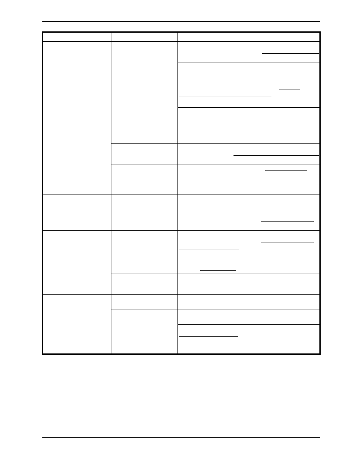
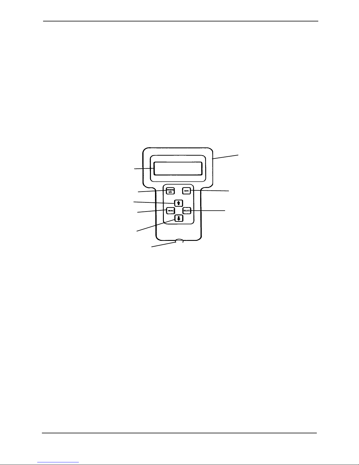
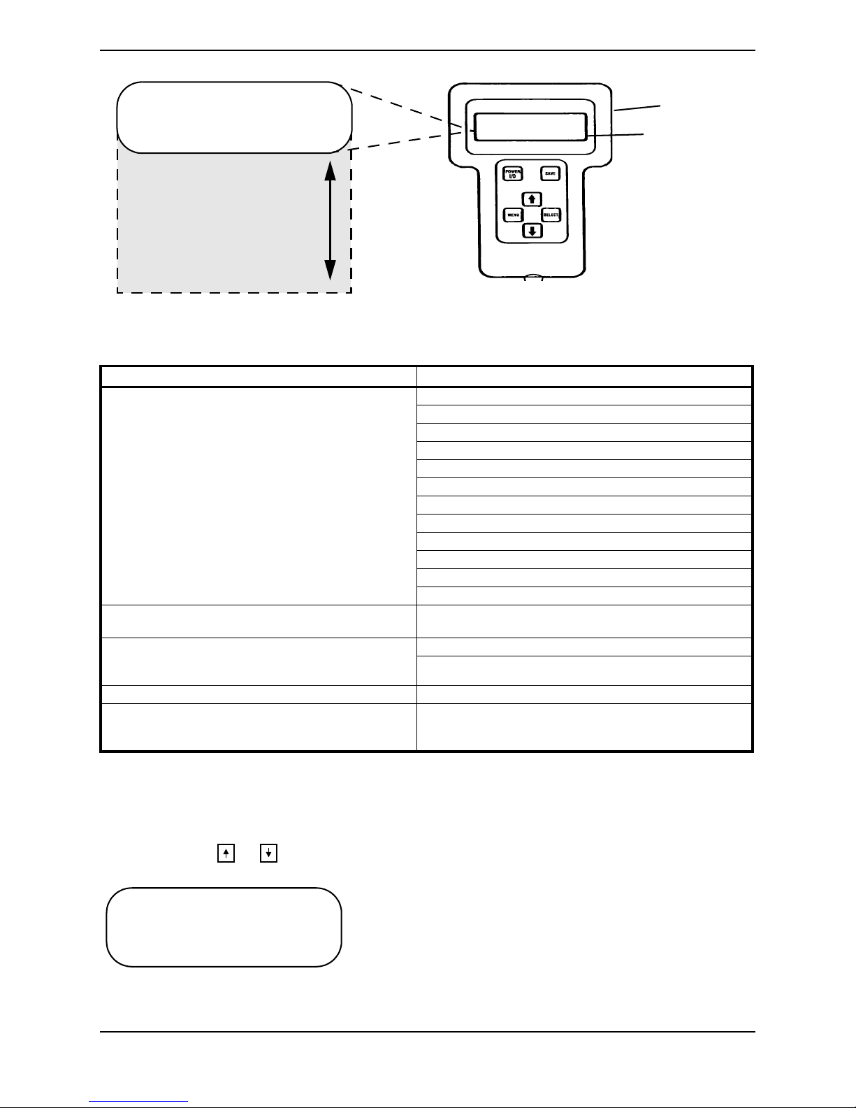
Overview
NOTE: For this procedure, refer to FIGURE 4.1.
The Remote Programmer is the information center of the control module. Through simple
key sequences, the Remote Programmer allows modification of the performance
characteristics, gives diagnostics information for trouble shooting and permits calibration
of the control module.
Remote Programmer
LCD Display
POWER Key
UP Key
MENU Key
DOWN Key
To Controller
SAVE Key
SELECT Key
FIGURE 4.1 Overview
Remote Programmer Terminology
Function
A function is a performance characteristic which can be adjusted or modified to improve
the operation of the wheelchair for a particular control need. Two (2) examples are:
The forward speed function may be adjusted to a higher or lower speed the same way as
you would adjust a trimpot in other controls.
Stand-by Mode Function may be turned ON or OFF the same as a switch would be used.
All functions are listed in a menu.
™
MK
EX™ and MK
5
™
TT-EX™ Electronics 18 Part No 1114808
5

SECTION 4—REMOTE PROGRAMMER
Value
Each function has a value. It is the degree or amount of the function which is used to
influence the overall wheelchair performance. Most values are numerical or in
percentages, for instance - high speed may be set to 75% of the wheelchair's maximum.
For others, the value is either ON or OFF, for example - Stand-by Mode. Changing a value
is called Adjustment.
Standard Program (Preset Programs)
The standard programs are fixed function values which are used as an initial set up point
from which individualization of the wheelchair performance can begin. Standard values
are NEVER altered or modified.
User Memory Values
The user memory values can only be changed through the Remote Programmer by first
modifying the temporary memory values and then by saving them in the user memory
where they become the user program. The Remote Programmer is activated by pressing
the POWER key when the wheelchair is in neutral. The wheelchair cannot be driven when
the LCD display is illuminated. The display will automatically turn itself OFF after 45
seconds if no keys are pressed. It can also be turned OFF by pressing the POWER key.
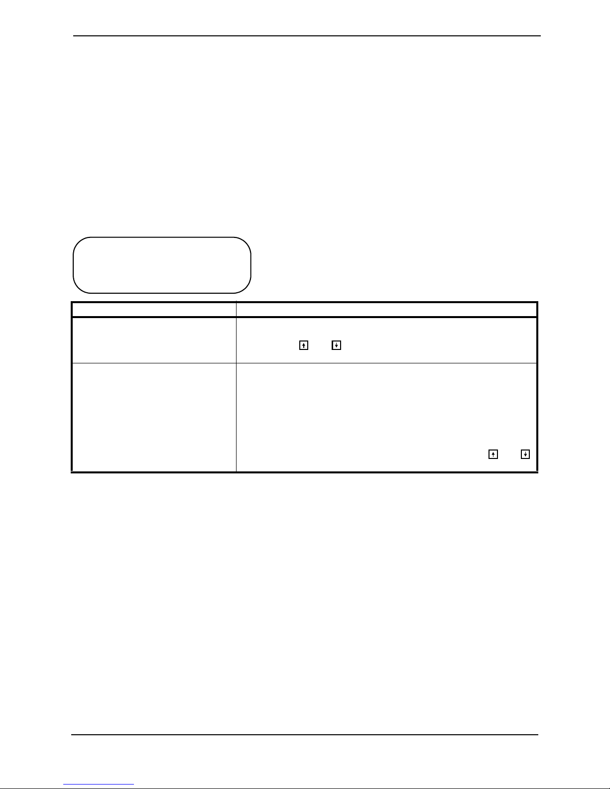
Description Of Remote Programmer Keys
KEY DESCRIPTION
POWER KEY The POWER key turns on and off the LCD display. Press the POWER key
once and the display will come ON. Press the POWER key again and the
display will turn OFF.
MENU KEY The MENU key returns the LCD display to the previous screen. If a func-
tion is being adjusted, pressing the MENU key returns the display to the
Performance Menu. Pressing the key again will cause the display to change
to the Main Menu.
UP AND DOWN
SELECT KEY The SELECT key chooses the item to which the selection arrow on the
SAVE KEY The SAVE key causes the Save screen to appear or causes the values that
KEYS
These keys are used to move the selection arrow on the LCD up and
down or adjust a value up or down. An adjusted value is not saved unless
the SAVE key is pressed.
LCD is pointing and displays the appropriate next screen.
have been modified in temporary memory to be permanently stored in the
driving program specified by the selection arrow.
Part No 1114808 19 MK
™
EX™ and MK
5
™
TT-EX™ Electronics
5
SECTION 5—PERFORMANCE ADJUSTMENTS
SECTION 5—PERFORMANCE
ADJUSTMENTS
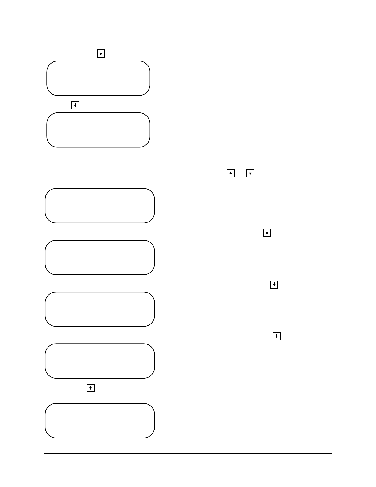
Speed and Response Screen
The first display screen shown after powering on the Remote Programmer is the Speed
and Response screen.
The first line shows the current drive. The second line shows the forward speed. The third
line shows the responsiveness of the wheelchair to changes in drive commands. The
fourth line is the entry point to the Main Menu.
DRIVE 1
➜ SPEED 95%
RESPONSE 50%
ADVANCED MENU
MENU ITEM DESCRIPTION
SPEED Adjusts the speed of the wheelchair. It affects forward speed, turning speed
and reverse speed simultaneously and uniformly. The fastest speed setting is
100%. Use the and to increase or decrease the speed of the wheelchair.
RESPONSE Adjusts the responsiveness or quickness of the wheelchair to changes in
drive commands. It affects acceleration, turn acceleration, turn deceleration, braking, torque and turning speed. The value of the Response parameter is set to 50% whenever a Standard Program is selected. It is good
practice to first select a standard program that is close to the desired performance and then use Response to individualize the driving performance
to the user. The Response parameter will be ineffective in making large
changes in wheelchair responsiveness, e.g. changing a fast/responsive drive
into one suitable for users needing tremor dampening. Use the and
to increase or decrease the responsiveness of the wheelchair.
Advanced Menu
Allows entry into the Main Menu where the Performance Adjust menu, Standard
Programs menu, Calibrations menu and Current Status menu are displayed. Press the
SELECT key to display the Main Menu.
Performance Menu
NOTE: For this procedure, refer to FIGURE 5.1.
Each of the standard joysticks and optional joysticks/devices has its own performance
menu. Only the menu for the particular configuration of the joystick and options
connected to the control module appear on the performance menu. Common to all of the
MK5 control systems are the following:
™
MK
EX™ and MK
5
™
TT-EX™ Electronics 20 Part No 1114808
5
SECTION 5—PERFORMANCE ADJUSTMENTS
➜ SPEED
RESPONSE
FORWARD SPD
TURNING SPD
ACCELERATION
TURN ACCELERATION
TURN DECELERATION
BRAKING
REVERSE SPEED
TORQUE
POWER LEVEL
JOYSTICK THROW
Remote
Programmer
LCD Display
FIGURE 5.1 Performance Menu
The following menu items are added as shown in the chart below:
JOYSTICK/OPTIONAL DEVICE ADDITIONAL MENU ITEM
THE MPJ JOYSTICK
1500M4 RIM
1558M4 COMPACT JOYSTICK
NOTE: The entire menu can be customized and stored in
four drive programs (DRIVE 1 - 4)
1812M4 DUAL PROPORTIONAL CONTROL INPUT SELECT - determines which driver control device is
ENVIRONMENTAL CONTROLS
(ACCESSED THROUGH AUX12 AND
AUX34)
MK5 SINGLE ACTUATOR CONTROL (SAC) SAC - Single Actuator
MK5 TAC
MK5 TRCM
MK5 TRECM
MOM/LATCH
LATCHED TYPE
MOM REVERSE
STANDBY MODE
STANDBY SEL
STANDBY TIME
RIM CONTROL
REMOTE SEL
AUDIBLE IND - Not available with MPJ joysticks
DISPLAY SELECT
AXES SELECTION
NO DRIVING
active in each driving program
ECU 1, ECU 2
ECU 3, ECU 4
Tilt/Recline
Making Performance Adjustments
The arrow to the left is the selection pointer. It can be moved up or down the main menu
by pressing the or key. The selection arrow points to PERFORMANCE ADJUST. To
select this activity press the SELECT key.
➜ PERFORMANCE ADJUST
STANDARD PROGRAMS
CALIBRATIONS
CURRENT STATUS
Part No 1114808 21 MK
™
EX™ and MK
5
™
TT-EX™ Electronics
5
SECTION 5—PERFORMANCE ADJUSTMENTS
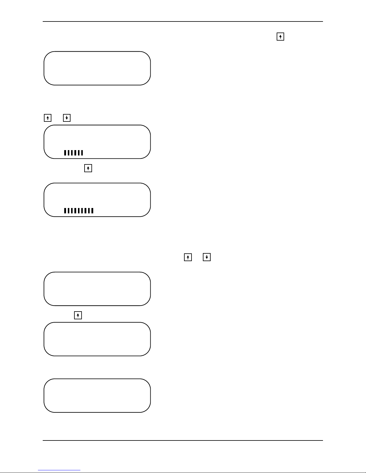
The display screen will change to show the driving programs available for programming.
The DPJ joystick has only two driving programs, only DRIVE 1 and DRIVE 2 will be
shown. Use the key to move the selection arrow down to select drives displayed.
➜ DRIVE 1
DRIVE 2
DRIVE 3
DRIVE 4
Use the key to move the selection arrow down.
DRIVE 1
➜ DRIVE 2
DRIVE 3
DRIVE 4
To view the menu for DRIVE 2 press the SELECT key. The display screen changes to show
the first four performance functions and the programmed values for the functions. The
selection arrow points to the first function. Pressing the or key will move the
selection arrow up or down.
➜ FORWARD SPD 95%
TURNING SPD 50%
ACCELERATION 30%
TURN ACCELERATION35%
Move the selection arrow down to TURNING SPD by pressing the key.
FORWARD SPD 95%
➜ TURNING SPD 50%
ACCELERATION 30%
TURN ACCELERATION35%
Move the selection arrow down to ACCELERATION by pressing the key again.
FORWARD SPD 95%
TURNING SPD 50%
➜ ACCELERATION 30%
TURN ACCELERATION35%
Move the selection arrow to TURN ACCELERATION by pressing the key again.
FORWARD SPD 95%
TURNING SPD 50%
ACCELERATION 30%
➜ TURN ACCELERATION 35%
Pressing the key again leaves the selection arrow in the same place and the entire
performance menu shifts up one line. The selection arrow now points to BRAKING.
TURNING SPD 50%
ACCELERATION 30%
TURN ACCELERATION35%
➜ BRAKING 35%
™
MK
EX™ and MK
5
™
TT-EX™ Electronics 22 Part No 1114808
5
SECTION 5—PERFORMANCE ADJUSTMENTS
To change the programmed value for TURN ACCELERATION, press the key so the
selection arrow points to TURN ACCELERATION.
TURNING SPD 50%
ACCELERATION 30%
➜ TURN ACCELERATION 35%
BRAKING 35%
Press the SELECT key. The display screen changes to the adjustment screen. The top line
shows the function. The second line shows the value. At the bottom is a bar graph which
shows the relative position of the current value to the total adjustment range. Pressing the
or key will adjust the value.
TURN ACCELERATION
35%
MORE
LESS
Pressing the key causes the value to increase and the bar graph to move toward
MORE.
TURN ACCELERATION
70%
MORE
LESS
If another change is needed, press the MENU key to change the screen back to the
performance menu and move the selection arrow to a new function. To save this change,
press the SAVE key to show the first save screen. The select arrow points to DRIVE 2. (The
DPJ joystick will show only two drive programs.) To select the drive program to which
the changes just made will be stored use the or key to move the selection arrow to
point to the intended drive program.
SAVE TO DRIVE 1
➜ DRIVE 2
DRIVE 3
DRIVE 4
Press the key to move the selection arrow up to DRIVE 1.
SAVE TO ➜ DRIVE 1
DRIVE 2
DRIVE 3
DRIVE 4
To store the program into DRIVE 1, press the SAVE key again. The display screen changes
to show that the command is being executed.
SAVING CHANGES TO
DRIVE 1
When saving to the drive program is complete, the screen will change to display:
Part No 1114808 23 MK
™
EX™ and MK
5
™
TT-EX™ Electronics
5
SECTION 5—PERFORMANCE ADJUSTMENTS
SAVING CHANGES TO
DRIVE 1
CONTINUE? PRESS MENU
QUIT? PRESS POWER
Pressing the MENU key allows the adjustment sequence to be repeated for other drive
programs or the new program can be test driven by pressing the POWER key to turn OFF
the display screen (The wheelchair cannot be driven while the display screen is ON.).
➜ P E R F O R M A N C E A D J U S T
STANDARD PROGRAMS
CALIBRATIONS
CURRENT STATUS
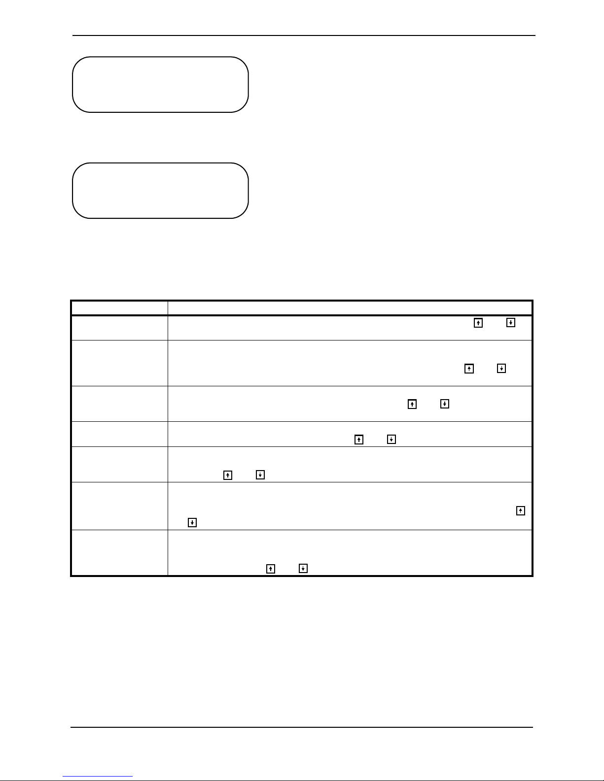
Performance Menu Description
The performance adjustment menu is listed with its display mnemonic and a description
of its function.
MENU ITEM DESCRIPTION
FORWARD SPEED
TURNING SPEED Sets the TURNING SPEED as a percentage of the maximum forward speed. The turning
ACCELERATION ACCELERATION sets the time that it takes the wheelchair to accelerate to its maximum
TURN
ACCELERATION
BRAKING BRAKING sets the response time to slow or stop the wheelchair. 100% represents the max-
TORQUE Adjusts the stiffness of the response and tracking ability of the wheelchair to joystick com-
POWER LEVEL POWER LEVEL is an adjustment to the current limit of the control. Lower values reduce the
Sets the maximum forward speed. The fastest speed setting is 100%. Use the and
keys to change the value.
speed is independent of the forward speed setting so that the turning speed can be greater
than the forward speed. The fastest turning speed setting is 60%. Use the and keys
to change the value.
speed. A value of 100% is the quickest acceleration. Use the and keys to change the
values.
TURN ACCELERATION is the response time to start turn commands. A value of 100% is
the quickest response to turn commands. Use and keys to change the value.
imum braking capability of the system. This function is independent of the acceleration setting. Use the and keys to change the value.
mands. A 100% value is the maximum stiffness while a 0% value is the maximum softness.
The MK5 TT-EX True Track Feature is turned off when the value is set to 0%. Use the
and keys to change the value.
maximum pulling power and increase the range of the wheelchair. Reduced power should be
used for chairs operated very slowly or child-sized chairs. A value of 100% provides full
power output. Use the and keys to change the value.
™
MK
EX™ and MK
5
™
TT-EX™ Electronics 24 Part No 1114808
5
 Loading...