

Invacare MK5 NX-80 ELECTRONICS Owner's Service Manual

OWNER’S/SERVICE MANUAL
MK
5
™
NX
™
- 80
ELECTRONICS
DEALER: THIS MANUAL MUST BE GIVEN TO THE USER
OF THE WHEELCHAIR.
USER: BEFORE USING THIS WHEELCHAIR, READ THIS
MANUAL AND SAVE FOR FUTURE REFERENCE.
For more information regarding
Invacare products, parts, and services,
please visit: www.invacare.co
m

SPECIAL NOTES
WARNING
DO NOT OPERATE THIS EQUIPMENT
WITHOUT FIRST READING AND
UNDERSTANDING THIS MANUAL. IF YOU
ARE UNABLE TO UNDERSTAND THE
WARNINGS, CAUTIONS, AND
INSTRUCTIONS, CONTACT A HEALTHCARE
PROFESSIONAL, DEALER OR TECHNICAL
SPECIAL NOTES
ATTEMPTING TO USE THIS EQUIPMENT -
WARNING notices as used in this manual apply to hazards or unsafe practices which could result in personal injury or property damage.
THE INFORMATION CONTAINED IN THIS DOCUMENT IS SUBJECT
TO CHANGE WITHOUT NOTICE.
REPAIR OR SERVICE INFORMATION
Setup of the Electronic Controller is to be performed ONLY by individuals certified by Invacare. The fine tuning adjustments of the controller
may affect other activities of the wheelchair. Damage to the equipment
could occur under these circumstances. If uncertified individuals perform
any work on these units, the warranty is void.
PERSONNEL IF APPLICABLE BEFORE
OTHERWISE INJURY OR DAMAGE MAY
RESULT.
SPECIAL NOTES
NOTICE
WARNING
OPERATING INFORMATION
Performance adjustments should only be made by professionals of the
health care field or persons fully conversant with this process and the
driver’s capabilities. Incorrect settings could cause injury to the driver,
bystanders, damage to the chair and surrounding property. After the
wheelchair has been setup, check to make sure that the wheelchair performs to the specifications entered in the setup procedure. If the wheelchair does NOT perform to specifications, turn the wheelchair OFF immediately and re-enter setup specifications. Repeat this procedure until
the wheelchair performs to specifications.
MK5™NX™- 80 ELECTRONICS 8-2 Part No. 1122140
WARNING

SPECIAL NOTES ............................................................................ 2
SECTION 1 - SPJ™-80 JOYSTICK .............................................................................................................6
SPECIAL NOTES
SECTION I REMOTE PROGRAMMER ...................................................................................... 7
SECTION II PERFORMANCE ADJUSTMENTS ........................................................................ 8
SECTION III STANDARD VALUE SETTINGS ......................................................................... 13
SECTION IV CALIBRATION OF CONTROL MODULE ...................................................... 14
SECTION V CURRENT STATUS DISPLAY .............................................................................16
SECTION VI DIAGNOSTICS CODES ....................................................................................... 17
SECTION VII INVACARE VIRTUAL SERVICE SETUP ............................................................ 18
SECTION VIII CONNECTOR DESCRIPTIONS ........................................................................ 20
SECTION IX CURRENT ROLLBACK......................................................................................... 21
TABLE OF CONTENTS
TABLE OF CONTENTS
TABLE OF CONTENTS
OWNER’S SECTION
SERVICE SECTION
LIMITED WARRANTY ........................................................................................................................... 23
Part No. 1122140 8-3 MK5™NX™- 80 ELECTRONICS

GENERAL GUIDELINES
CAUTION: IT IS VERY IMPORTANT THAT YOU READ THIS INFORMATION REGARDING THE POSSIBLE EFFECTS OF ELECTRO-MAGNETIC INTERFERENCE ON YOUR POWERED WHEELCHAIR.
Electromagnetic Interference (EMI) From Radio Wave Sources
Powered wheelchairs and motorized scooters (in this text, both will be
referred to as powered wheelchairs) may be susceptible to electro-magnetic interference (EMI), which is interfering electromagnetic energy
(EM) emitted from sources such as radio stations, TV stations, amateur
radio (HAM) transmitters, two way radios and cellular phones. The interference (from radio wave sources) can cause the powered wheelchair to
release its brakes, move by itself or move in unintended directions. It can
GENERAL GUIDELINES
also permanently damage the powered wheelchair’s control system. The
intensity of the interfering EM energy can be measured in volts per meter
(V/m). Each powered wheelchair can resist EMI up to a certain intensity.
This is called its immunity level. The higher the immunity level, the
greater the protection. At this time, current technology is capable of
achieving at least a 20 V/m immunity level, which would provide useful
protection from the more common sources of radiated EMI.
GENERAL WARNINGS
There are a number of sources of relatively intense electromagnetic fields
in the everyday environment. Some of these sources are obvious and easy
to avoid. Others are not apparent and exposure is unavoidable. However,
we believe that by following the warnings listed below, your risk to EMI
will be minimized.
The sources of radiated EMI can be broadly classified into three types:
1) Hand-held portable transceivers (transmitters-receivers with the
antenna mounted directly on the transmitting unit). Examples include: citizens band (CB) radios, walkie talkie, security, fire, and
police transceivers, cellular telephones and other personal communication devices.
NOTE: Some cellular telephones and similar devices transmit signals
while they are ON, even when not being used;
2) Medium-range mobile transceivers, such as those used in police cars,
fire trucks, ambulances and taxis. These usually have the antenna
mounted on the outside of the vehicle.
3) Long-range transmitters and transceivers, such as commercial
broadcast transmitters (radio and TV broadcast antenna towers)
and amateur (HAM) radios.
NOTE: Other types of hand-held devices, such as cordless phones, laptop
computers, AM/FM radios, TV sets, CD players, cassette players and
small appliances, such as electric shavers and hair dryers, so far as we
know, are not likely to cause EMI problems to your powered wheelchair.
MK5™NX™- 80 ELECTRONICS 8-4 Part No. 1122140

GENERAL GUIDELINES
GENERAL WARNINGS
POWERED WHEELCHAIR ELECTROMAGNETIC INTERFERENCE
(EMI)
Because EM energy rapidly becomes more intense as one moves closer to
the transmitting antenna (source), the EM fields from hand-held radio
wave sources (transceivers) are of special concern. It is possible to unintentionally bring high levels of EM energy very close to the powered
wheelchair’s control system while using these devices. This can affect
powered wheelchair movement and braking. Therefore, the warnings
listed below are recommended to prevent possible interference with the
control system of the powered wheelchair.
Electromagnetic interference (EMI) from sources such as radio and TV
stations, amateur radio (HAM) transmitters, two-way radios and cellular
phones can affect powered wheelchairs and motorized scooters. Following the warnings listed below should reduce the chance of unintended
brake release or powered wheelchair movement which could result in
serious injury.
GENERAL GUIDELINES
1) Do not operate hand-held transceivers (transmitters receivers), such
as citizens band (CB) radios or turn ON personal communication
devices, such as cellular phones, while the powered wheelchair is
turned ON.
2) Be aware of nearby transmitters, such as radio or TV stations and try
to avoid coming close to them.
3) If unintended movement or brake release occurs, turn the powered
wheelchair OFF as soon as it is safe.
4) Be aware that adding accessories or components, or modifying the
powered wheelchair, may make it more susceptible to EMI (Note:
There is no easy way to evaluate their effect on the overall immunity
of the powered wheelchair).
5) Report all incidents of unintended movement or brake release to the
powered wheelchair manufacturer and note whether there is a source
of EMI nearby.
IMPORTANT INFORMATION
1) 20 volts per meter (V/m) is a generally achievable and useful immunity
level against EMI, as of May 1994. (the higher the level, the greater
the protection).
2) This device has been tested to a radiated immunity level of 20 volts
per meter.
Part No. 1122140 8-5 MK5™NX™- 80 ELECTRONICS
OWNER’S SECTION I
SPJ-80 JOYSTICK
I. SPJ-80 JOYSTICK
(FIGURE 1)(FIGURE 1)
(FIGURE 1)
(FIGURE 1)(FIGURE 1)
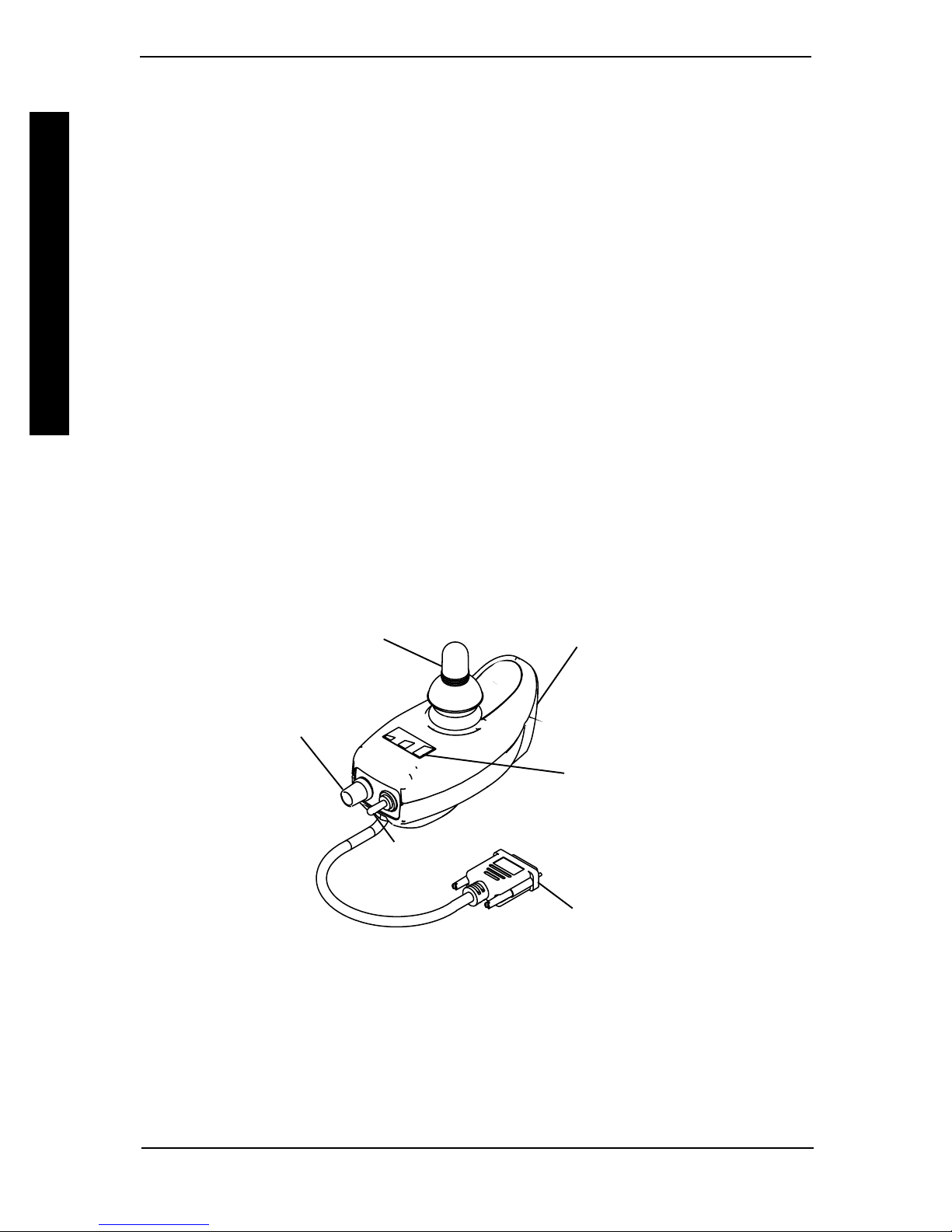
ON/OFF SWITCH - Two (2) position toggle is located at the back of the joystick housing.
SPEED CONTROL - Rotary knob is located on the back of the joystick housing. Turning
the knob clockwise increases the maximum speed of the chair.
JOYSTICK - Proportional drive control located at the front of the joystick housing provides smooth control of speed and direction.
SPJ-80 JOYSTICK
BATTERY GAUGE DISPLAY (BGD) - Located at the rear of the joystick housing, it
provides information on the remaining charge in the batteries. At full charge all six (6)
segments of the bar graph are lighted; as the battery becomes discharged the farthest right
segment will go out until only the red bar is lighted; at this level the last red bar will start to
flash on and off to indicate that the user should charge the batteries as soon as possible.
The BGD also serves as a system diagnostic device when a fault is detected by the control
module. A specific number of flashes of the last two red bars (up to eight (8) flashes) will
start to flash on and off to indicate the type of fault detected separated by a pause. A chart of
the diagnostic indications is given in the DIAGNOSTIC CODE section of this manual.
- SWITCHES AND INDICATORS- SWITCHES AND INDICATORS
- SWITCHES AND INDICATORS
- SWITCHES AND INDICATORS- SWITCHES AND INDICATORS
Speed
Control
Charger/
Programming
Joystick
Battery
Gauge
Display
On/Off
Switch
FIGURE 1 – SPJ-80 JOYSTICK
Battery
Port
To Controller
MK5™NX™- 80 ELECTRONICS 8-6 Part No. 1122140
REMOTE PROGRAMMER (OPTIONAL)
SERVICE SECTION I
SERVICE SECTION
WARNING
Setup of the Electronic Controller is to be performed ONLY by individuals certified by Invacare. Fine tuning adjustments of the controller may
affect other activities of the wheelchair. Damage to the equipment could
occur under these circumstances. If uncertified individuals perform any
work on these units, the warranty is void.
OPERATING INFORMATION
WARNING
Performance adjustments MUST only be made by professionals of the
health care field or persons fully conversant with this process and the
drivers capabilities. Incorrect settings could cause injury to the driver,
bystanders, damage to the chair and surrounding property. After the
wheelchair has been setup, check to make sure that the wheelchair performs to the specifications entered in the setup procedure. If the wheelchair does NOT perform to specifications, turn the wheelchair OFF immediately and reenter setup specifications. Repeat this procedure until
the wheelchair performs to specifications.
SERVICE SECTION
I. REMOTE PROGRAMMER (OPTIONAL)I. REMOTE PROGRAMMER (OPTIONAL)
I. REMOTE PROGRAMMER (OPTIONAL)
I. REMOTE PROGRAMMER (OPTIONAL)I. REMOTE PROGRAMMER (OPTIONAL)
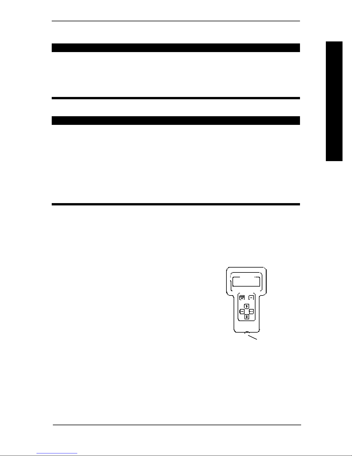
The Remote Programmer is the information center of the control module. Through
simple key sequences, the Remote Programmer allows modification of the performance
characteristics, gives diagnostics information for trouble shooting and permits calibration of the control module. Some terms which will be used in the discussion of the
Remote Programmer are explained here:
1. FUNCTION – A function is a performance characteristic which can be adjusted or modified to alter the
operation of the chair for a particular user control
need. Two (2) examples are:
The high speed function may be adjusted to a
higher or lower speed the same way as you would
adjust a trimpot in other controls.
Stand-by Mode Function may be turned ON or
OFF the same as a switch would be used. All
functions are listed in a menu.
2. VALUE – Each function has a value. It is the degree or
amount of the function which is used to influence the
overall chair performance. Most values are numerical or in percentages, for instance –
high speed may be set to 75% of the chair’s maximum. For others, the value is either
ON or OFF, for example – Stand-by Mode. Changing a value is called adjustment.
FIGURE 3 – REMOTE
PROGRAMMER
To Controller
3. STANDARD PROGRAM (Preset Programs) – The standard programs are fixed
function values which are used as an initial set up point from which individualization of
the chair performance can begin. Standard values are NEVER altered or modified.
Part No. 1122140 8-7 MK5™NX™- 80 ELECTRONICS
SERVICE SECTION II
4. The user memory values can only be changed through the Remote Programmer by
first modifying the temporary memory values and then by saving them in the user
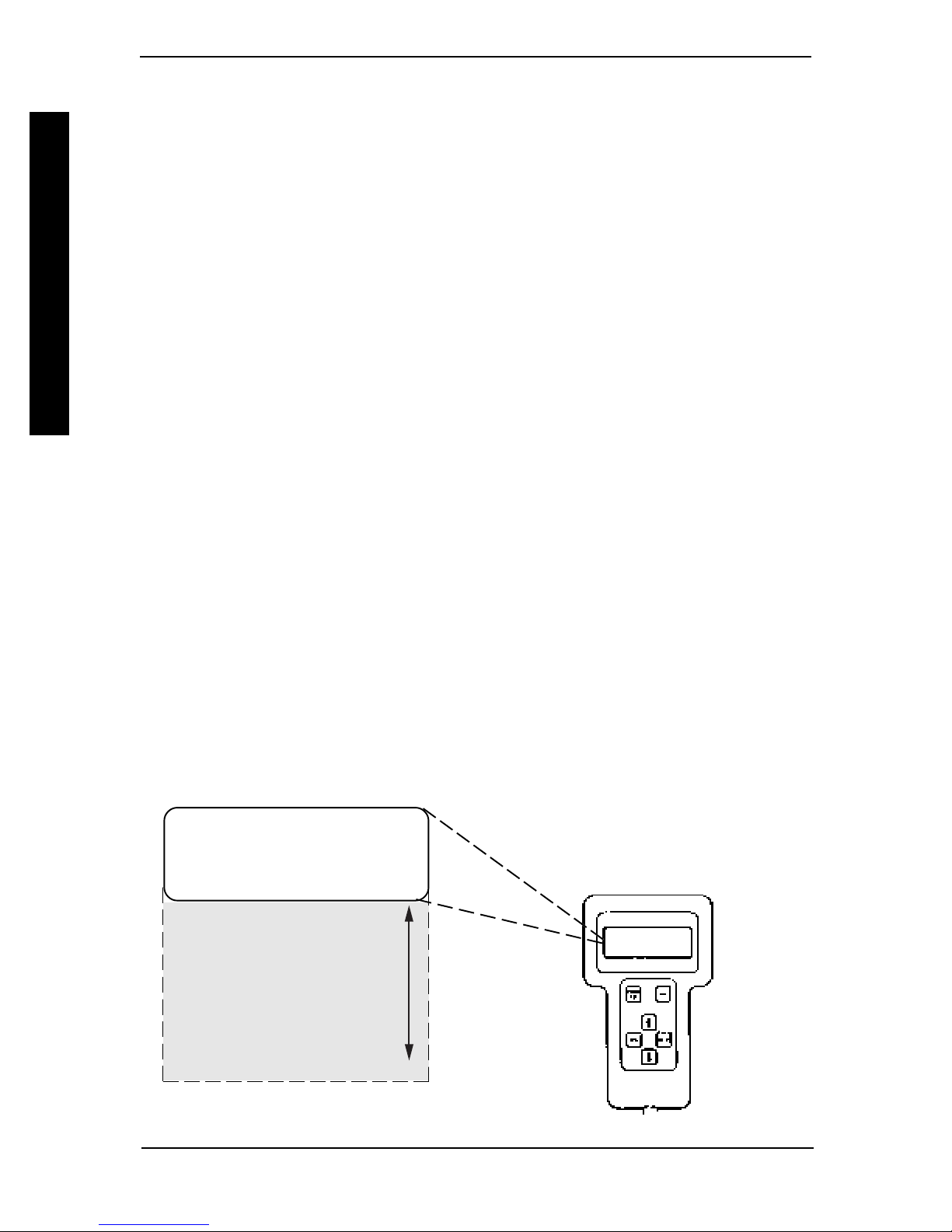
memory where they become the user program. The Remote Programmer is activated by pressing the POWER key when the chair is in neutral. The chair cannot be
driven when the LCD display is illuminated. The display will turn itself OFF after 45
seconds. It can also be turned OFF by pressing the POWER key. The following is a
description of the operation of each of the keys:
POWER Key The POWER key turns on and off the LCD display. Press the
POWER key once and the display will come ON. Press the POWER
key again and the display will turn OFF.
MENU Key The MENU key returns the LCD display to the previous screen. If a
function is being adjusted, pressing the MENU key returns the display
to the Performance Menu. Pressing the key again will cause the
display to change to the Main Menu.
PERFORMANCE ADJUSTMENTS
and Keys These keys are used to move the selection arrow on the LCD up
and down or adjust a value up or down. An adjusted value is not
saved unless the SAVE key is pressed.
PERFORMANCE ADJUSTMENTS
SELECT Key The SELECT key chooses the item to which the selection arrow on
the LCD is pointing and displays the appropriate next screen.
SAVE Key The SAVE key causes the Save screen to appear or causes the values
that have been modified in temporary memory to be permanently
stored in the driving program specified by the selection arrow.
II. PERFORMANCE ADJUSTMENTS
PERFORMANCE MENUPERFORMANCE MENU
PERFORMANCE MENU
PERFORMANCE MENUPERFORMANCE MENU
Each of the standard joysticks and optional joysticks/devices has its own performance
menu. Only the menu for the particular configuration of the joystick and options connected to the control module appear on the performance menu. Common to all of the
MK5 control systems are the following:
SPEED
RESPONSE
FORWARD SPD
TURNING SPD
ACCELERATION
TURN ACCELERATION
TURN DECELERATION
BRAKING
REVERSE SPD
TORQUE
POWER LEVEL
JOYSTICK THROW
MK5™NX™- 80 ELECTRONICS 8-8 Part No. 1122140
 Loading...