

Invacare MicroAir MA60, MicroAir MA65, MicroAir MA65B42, MicroAir MA65B48, MicroAir MA65RSR User Manual
User Manual
This manual MUST be given to the user of the product.
BEFORE using this product, read this manual and save for future reference.
EN
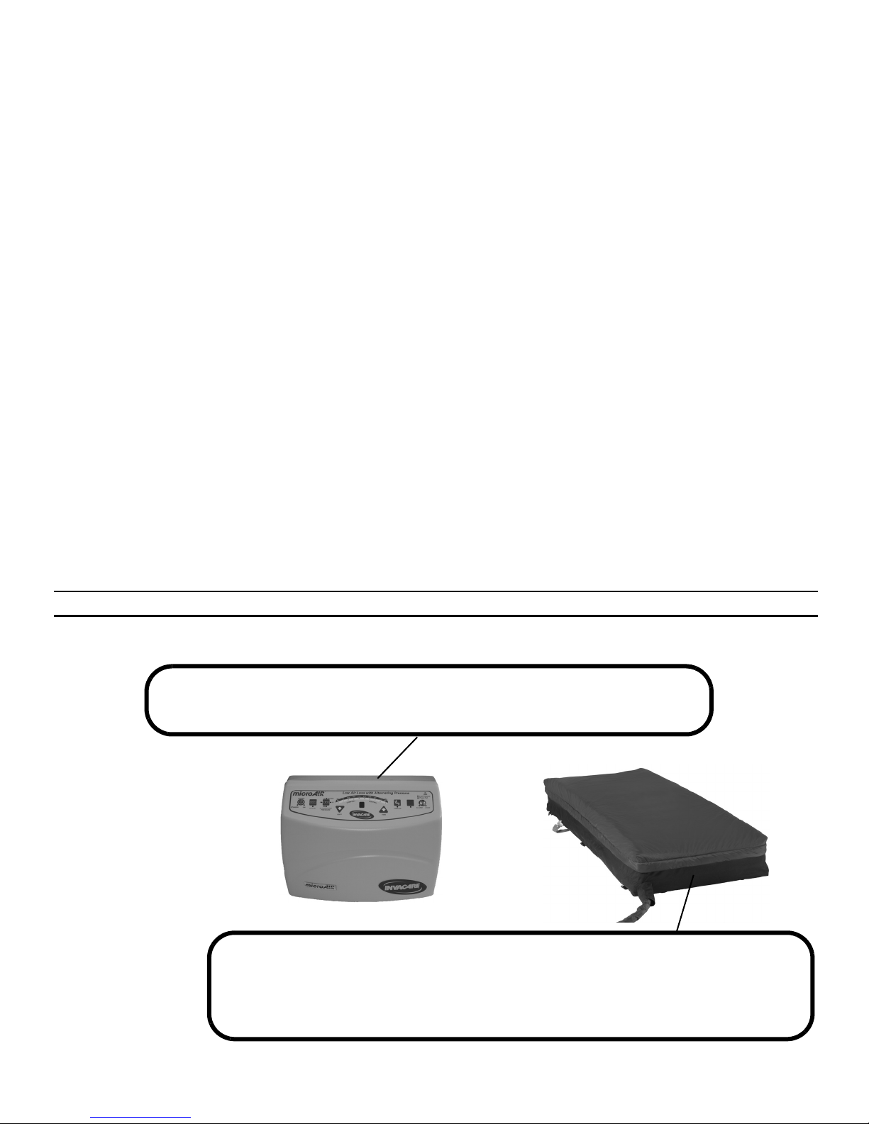
Invacare®MA60 Series
MA60 Alternating Pressure System
MA65 Alternating Pressure On-Demand Low Air Loss System
MA65B42 microAir Alternating Pressure with Low Air Loss System - Bariatric (42 inch)
MA65B48 microAir Alternating Pressure with Low Air Loss System - Bariatric (48 inch)
MA65RSR microAir Alternating Pressure with Low Air Loss System and Raised Side Rails

Invacare®MA60 Series 2 Part No 1148137
© 2011 Invacare Corporation. All rights reserved. Republication, duplication or modification in whole or in part is prohibited without prior written
permission from Invacare. Trademarks are identified by ™ and ®. All trademarks are owned by or licensed to Invacare Corporation or its subsidiaries
unless otherwise noted.

2 GENERAL
Part No 1148137 3 Invacare®MA60 Series
2 General
2.1 Symbols
Warnings
Signal words are used in this manual and apply to hazards or unsafe practices which could result in personal injury or property damage.
See the information below for definitions of the signal words.
DANGER
Danger indicates an imminently hazardous situation which, if not avoided, will result in death or serious injury.
WARNING
Warning indicates a potentially hazardous situation which, if not avoided, could result in death or serious injury.
CAUTION
Caution indicates a potentially hazardous situation which, if not avoided, may result in property damage or minor injury or
both.
!
IMPORTANT
Indicates a hazardous situation that could result in damage to property if it is not avoided.
Gives useful tips, recommendations and information for efficient, trouble-free use.

2 GENERAL
Invacare®MA60 Series 4 Part No 1148137
2.2 Limited Warranty
PLEASE NOTE: THE WARRANTY BELOW HAS BEEN DRAFTED TO COMPLY WITH FEDERAL LAW APPLICABLE TO PRODUCTS
MANUFACTURED AFTER JULY 4, 1975.
This warranty is extended only to the original purchaser who purchases this product when new and unused from Invacare or a dealer. This warranty is
not extended to any other person or entity and is not transferable or assignable to any subsequent purchaser or owner. Coverage under this warranty
will end upon any such subsequent sale or other transfer of title to any other person.
This warranty gives you specific legal rights and you may also have other legal rights which vary from state to state.
Invacare warrants the mattress and cover when purchased new and unused to be free from defects in materials and workmanship for a period of one
year from the date of purchase from Invacare or a dealer, with a copy of the seller’s invoice required for coverage under this warranty. Invacare
warrants the control unit when purchased new and unused to be free from defects in materials and workmanship for a period of two years from the date
of purchase from Invacare or a dealer, with a copy of the seller’s invoice required for coverage under this warranty.If within such warranty period any
such product shall be proven to be defective, such product shall be repaired or replaced, at Invacare's option. This warranty does not include any labor
or shipping charges incurred in replacement part installation or repair of any such product. Invacare's sole obligation and your exclusive remedy under
this warranty shall be limited to such repair and/or replacement.
For warranty service, please contact the dealer from whom you purchased your Invacare product. In the event you do not receive satisfactory warranty
service, please write directly to Invacare at the address on the back cover. Provide dealer's name, address, model number, and the date of purchase,
indicate nature of the defect and, if the product is serialized, indicate the serial number.
Invacare Corporation will issue a return authorization. The defective unit or parts must be returned for warranty inspection using the serial number,
when applicable, as identification within thirty days of return authorization date. DO NOT return products to our factory without our prior consent.
C.O.D. shipments will be refused; please prepay shipping charges.
LIMITATIONS AND EXCLUSIONS: THE WARRANTY SHALL NOT APPLY TO PROBLEMS ARISING FROM NORMAL WEAR OR FAILURE TO
ADHERE TO THE ENCLOSED INSTRUCTIONS. IN ADDITION, THE FOREGOING WARRANTY SHALL NOT APPLY TO SERIAL NUMBERED
PRODUCTS IF THE SERIAL NUMBER HAS BEEN REMOVED OR DEFACED; PRODUCTS SUBJECTED TO NEGLIGENCE, ACCIDENT,
IMPROPER OPERATION, MAINTENANCE OR STORAGE; OR PRODUCTS MODIFIED WITHOUT INVACARE'S EXPRESS WRITTEN CONSENT
INCLUDING, BUT NOT LIMITED TO: MODIFICATION THROUGH THE USE OF UNAUTHORIZED PARTS OR ATTACHMENTS: PRODUCTS
DAMAGED BY REASON OF REPAIRS MADE TO ANY COMPONENT WITHOUT THE SPECIFIC CONSENT OF INVACARE; PRODUCTS
DAMAGED BY CIRCUMSTANCES BEYOND INVACARE'S CONTROL; PRODUCTS REPAIRED BY ANYONE OTHER THAN AN INVACARE
DEALER, SUCH EVALUATION SHALL BE SOLELY DETERMINED BY INVACARE.
THE FOREGOING EXPRESS WARRANTY IS EXCLUSIVE AND IN LIEU OF ALL OTHER EXPRESS WARRANTIES WHATSOEVER, WHETHER
EXPRESS OR IMPLIED, INCLUDING THE IMPLIED WARRANTIES OF MERCHANTABILITY AND FITNESS FOR A PARTICULAR PURPOSE
AND THE SOLE REMEDY FOR VIOLATIONS OF ANY WARRANTY WHATSOEVER, SHALL BE LIMITED TO REPAIR OR REPLACEMENT OF
THE DEFECTIVE PRODUCT PURSUANT TO THE TERMS CONTAINED HEREIN. THE APPLICATION OF ANY IMPLIED WARRANTY
WHATSOEVER SHALL NOT EXTEND BEYOND THE DURATION OF THE EXPRESS WARRANTY PROVIDED HEREIN. INVACARE SHALL
NOT BE LIABLE FOR ANY CONSEQUENTIAL OR INCIDENTAL DAMAGES WHATSOEVER.
THIS WARRANTY SHALL BE EXTENDED TO COMPLY WITH STATE/PROVINCIAL LAWS AND REQUIREMENTS.

CONTENTS
Part No 1148137
5 Invacare®MA60 Series
2 GENERAL 3
Symbols .................................................................................................................................................................................................................................................... 3
Limited Warranty .................................................................................................................................................................................................................................. 4
4OVERVIEW 6
Label Location......................................................................................................................................................................................................................................... 6
Typical Product Parameters ................................................................................................................................................................................................................ 7
5 GENERAL GUIDELINES 10
General Guidelines ..............................................................................................................................................................................................................................10
Entrapment May Occur......................................................................................................................................................................................................................12
Electrical.................................................................................................................................................................................................................................................14
6OPERATION 15
Installing the Powered Mattress .......................................................................................................................................................................................................15
Installing the Bed Side Rails................................................................................................................................................................................................................17
Installing the Control Unit................................................................................................................................................................................................................. 18
Connecting the Hose.......................................................................................................................................................................................................................... 18
Connecting the Power Cord.............................................................................................................................................................................................................20
Using the Front Panel..........................................................................................................................................................................................................................21
Powering Up the System....................................................................................................................................................................................................................27
Placing the Patient on the Mattress.................................................................................................................................................................................................27
Transferring Patient From/To a Gurney......................................................................................................................................................................................... 28
Transferring Patient From/To a Wheelchair.................................................................................................................................................................................29
Preparing for CPR Procedure........................................................................................................................................................................................................... 29
About Power Outage and Transportation.....................................................................................................................................................................................30
7 MAINTENANCE AND TROUBLESHOOTING 31
Cleaning the System............................................................................................................................................................................................................................ 31
Troubleshooting...................................................................................................................................................................................................................................34
4 OVERVIEW
Invacare®MA60 Series 6 Part No 1148137
4 Overview
4.1 Label Location
DANGER-EXPLOSION HAZARD: DO NOT use in the presence of flammable anesthetics.
CAUTION: Equipment should be connected to a properly grounded receptacle (3-prong). Risk of
Electrical shock. DO NOT remove back. Disconnect air hose before administering CPR.
WARNING
Patient entrapment with bed side rails may cause injury or death. Mattress MUST fit bed frame and side rails
snugly to prevent patient entrapment. Follow the manufacturer’s instructions. Monitor patient frequently.
Read and understand the Owner’s/Operator’s Manual prior to using this equipment. Invacare product
manuals are available at www.invacare.com or your dealer. p/n 1150708 Rev A
This label is on the back of
the unit and also contains
the serial number

4 OVERVIEW
Part No 1148137 7 Invacare®MA60 Series
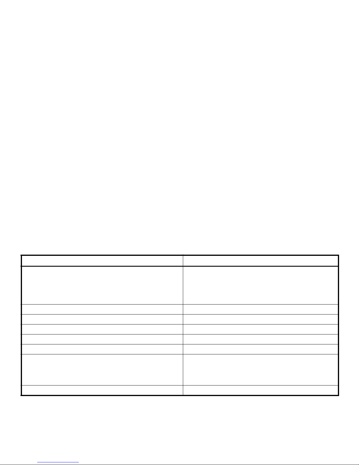
4.2 Typical Product Parameters
Electrical Parameters
MA65 Power unit is also used on MA65B42, MA65B48, and MA65RSR.
MA60/MA65
INPUT VOLTAGE AC:
110 V
INPUT FREQUENCY:
60 Hz
CURRENT:
1 A
MAXIMUM POWER
CONSUMPTION:
30 ± 10 W
CIRCUIT PROTECTION:
Dual fused,
250 V,
1 A fast blow fuses
MODE OF OPERATION:
Continuous
4 OVERVIEW
Invacare®MA60 Series 8 Part No 1148137
Performance Parameters
MA60/MA65
WEIGHT CAPACITY
STANDARD MATTRESS (36 INCH):
BARIATRIC MATTRESS:
42 INCH MATTRESS:
48 INCH MATTRESS:
350 lbs
650 lbs
1000 lbs
PRESSURE ZONE:
2
MAXIMUM FLOW:
50 ± 15 LPM
MAXIMUM FLOW PRESSURE:
35 ± 5 mmHg
MAXIMUM FLOW TIMER:
30 minutes
SUPPORT SURFACE INFLATION TIME:
5 -10 minutes
PATIENT COMFORT CONTROL PRESSURES
SOFT PRESSURE:
FIRM PRESSURE:
CYCLE TIME:
8 ± 4 mmHg
32 ± 4 mmHg
5, 10, 15, 20 minutes
PATIENT CONTACT:
Control unit and mattress have Latex-Free components
4 OVERVIEW
Part No 1148137 9 Invacare®MA60 Series
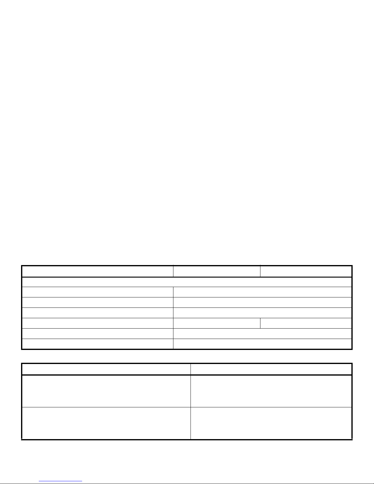
Mechanical Parameters
Environmental Parameters
MA60 MA65
CONTROL UNIT
DIMENSIONS (L X W X H):
15” x 6.5” x 11”
WEIGHT:
15 lbs
POWER CORD:
10 - 14 Feet Long, Hospital Grade
CONNECTION:
Two ¼” Flow Couplings Three ¼” Flow Couplings
PACKAGING:
1 piece/box
AIR FILTER:
None
MA60/MA65
OPERATING CONDITIONS
AMBIENT TEMPERATURE:
RELATIVE HUMIDITY:
ATMOSPHERIC PRESSURE:
50° - 95° F
30% - 75% Non-Condensing
70 - 106 kPa
STORAGE AND SHIPPING CONDITIONS
AMBIENT TEMPERATURE:
RELATIVE HUMIDITY:
ATMOSPHERIC PRESSURE:
-40° - 158° F
10% - 100%
50 - 106 kPa

5 GENERAL GUIDELINES
Invacare®MA60 Series 10 Part No 1148137
5 General Guidelines
5.1 General Guidelines
Contraindications
WARNING
DO NOT use this product or any available optional equipment without first completely reading and understanding these
instructions and any additional instructional material such as owner’s manuals, service manuals or instruction sheets
supplied with this product or optional equipment. If you are unable to understand the warnings, cautions or instructions,
contact a healthcare professional, dealer or technical personnel before attempting to use this equipment - otherwise, injury
or damage may occur.
ACCESSORIES WARNINGS
Invacare products are specifically designed and manufactured for use in conjunction with Invacare accessories. Accessories
designed by other manufacturers have not been tested by Invacare and are not recommended for use with Invacare
products.
!
NOTICE
THE INFORMATION CONTAINED IN THIS DOCUMENT IS SUBJECT TO CHANGE WITHOUT NOTICE.
Check all parts for shipping damage and test before using. In case of damage, DO NOT use. Contact Invacare/Carrier for
further instruction.
WARNING
Always consult the patient’s physician before using the MA60, MA65, MA65B42, MA65B48, and MA65RSR systems.

5 GENERAL GUIDELINES
Part No 1148137 11 Invacare®MA60 Series
Installation
WARNING
The MA60 and MA65 systems (including bariatric and raised side rail) is recommended to be installed on medical bed
frames with bed side or assist rails. It is preferred that the rails be in the raised position whenever a patient is on the bed.
Health care professionals assigned to each case should make the final determination whether side or assist rails are
warranted after assessing patient risks of entrapment and falls in accordance with State patient restraint legislation or facility
interpretation of such legislation.
Controls on the footboard may be obstructed by the control unit on a few bed frames. It may be necessary to relocate the
control unit. Refer to Installing the Control Unit
on page 18.
Check that air hoses and power cord are clear of the moving bed components before placing a patient on the bed. Operate
all motorized functions through their full range of motion to be certain that there is no pulling, interference or pinching.
 Loading...