

Invacare Matrix MX1 User Manual
This manual MUST be given to the user of the product.
BEFORE using this product, read this manual and save for future reference.
Invacare® Matrx®
MX1
IMX1
EN Back Cushion
User Manual ..........................................................................................3
FR Coussin de dossier
Manuel d’utilisation ............................................................................28
DE Rückenkissen
Gebrauchsanweisung ........................................................................56
ES Respaldo
Manual del usuario .............................................................................84
PT Almofada de Encosto
Manual de utilização ........................................................................113
IT Cuscino dello schienale
Manuale Utente ................................................................................141
DA Rygpude
Brugsanvisning ..................................................................................168
SV Ryggstödsdynan
Bruksanvisning ..................................................................................194
FI Selkänojan pehmuste
Käyttöopas ........................................................................................222
NL Rugkussen
Gebruikershandleiding ....................................................................248
EE Seljatoe padi
Kasutusjuhend ..................................................................................275
LT Nugaros pagalvėlės
Naudotojo vadovas .........................................................................300
CS Čalounění opěradla
Návod k použití ................................................................................325

Invacare® Matrx® MX1
2
Part No. 1176090
EN
This product complies with Directive 93/42/EEC concerning medical devices.
The launch date of this product is stated in the CN declaration of conformity.
FR
Ce produit est conforme à la Directive 93/42/CEE sur les dispositifs médicaux.
La date de lancement de ce produit est indiquée dans la déclaration de conformité CN.
DE
Dieses Produkt entspricht der Richtlinie 93/42/EWG über Medizinprodukte.
Das Einführungsdatum für dieses Produkt ist in der CN-Konformitätserklärung angegeben.
ES
Este producto cumple con la Directiva 93/42/EEC en lo concerniente a dispositivos médicos.
La fecha de lanzamiento de este producto figura en la declaración de conformidad de CN.
PT
Este produto está em conformidade com a Directiva 93/42/CEE sobre dispositivos médicos.
A data de lançamento deste produto é indicada na declaração de conformidade da CN.
IT
Questo prodotto è conforme alla direttiva 93/42/CEE riguardante i dispositivi medici.
La data di lancio di questo prodotto è indicata nella dichiarazione di conformità CN.
DA
Dette produkt overholder EU-direktivet 93/42/EØF om medicinsk udstyr.
Lanceringsdatoen for dette produkt fremgår af CE-overensstemmelseserklæringen.
SV
Den här produkten uppfyller kraven i direktiv 93/42/EEG om medicintekniska produkter.
Lanseringsdatum för den här produkten anges i CN-försäkran om överensstämmelse.
FI
Tämä tuote täyttää lääkintälaitteita koskevan 93/42/ETY-direktiivin.
Tämän tuotteen julkaisupäivämäärä on mainittu CN-vaatimustenmukaisuusvakuutuksessa.
NL Dit product voldoet aan richtlijn 93/42/EEG van de Raad betreffende medische hulpmiddelen.
De lanceringsdatum van dit product staat vermeld in de EG-verklaring van overeenstemming.
EE
Toode vastab meditsiiniseadmete direktiivile 93/42/EÜ.
Toote turule toomise kuupäev on kirjas CN-i vastavusavalduses.
LT
Šis gaminys atitinka medicinos prietaisų direktyvą 93/42/EEB.
Šio gaminio pristatymo rinkoje data yra nurodyta CN atitikties deklaracijoje.
CS
Tento výrobek vyhovuje požadavkům směrnice 93/42/EHS o zdravotnických prostředcích.
Datum uvedení tohoto výrobku na trh je uvedeno v prohlášení o shodě se směrnicemi ES.
© 2012 Motion Concepts. All rights reserved. Republication, duplication or modification in whole or in part is prohibited without prior written permission from Motion
Concepts. Trademarks are identified by ™ and ®. All trademarks are owned by or licensed to Motion Concepts or its subsidiaries unless otherwise noted.

CONTENTS
Part No. 1176090
3
Invacare® Matrx® MX1
1 GENERAL 4
Symbols........................................................................................................................4
Overview.....................................................................................................................4
Important Information ......................................................................................4
Invacare Matrx MX1..........................................................................................4
Outer Cover .......................................................................................................5
Limited Warranty......................................................................................................5
2SAFETY 6
General Guidelines ...................................................................................................6
Intended Use ..............................................................................................................6
Installation Information............................................................................................6
Operating Information .............................................................................................7
Weight Limitation and Model Numbers..............................................................7
3 MONO MOUNT 8
Installation Overview ...............................................................................................8
Included Items.....................................................................................................8
Tools Required ..........................................................................................................8
Before Installation .....................................................................................................8
Installing the Mounting Hardware .........................................................................9
Installing the Tracking Plate on the Back Shell ................................................ 11
Installing the Back Shell onto the Mounting Hardware.................................11
Adjusting the Back Height.................................................................................... 12
Adjusting the Back Angle...................................................................................... 12
Removing the Mono Mount Hardware............................................................. 13
4 FIXED DUAL MOUNT 14
Installation Overview ............................................................................................ 14
Included Items.................................................................................................. 14
Tools Required ....................................................................................................... 14
Before Installation .................................................................................................. 14
Installing the Angle Adjustable Brackets onto the Back Shell...................... 15
Clamp Body Adjustment ......................................................................................15
Installing the Band Clamps ................................................................................... 16
Installing the Back ...................................................................................................16
Adjusting the Back Height.....................................................................................18
Adjusting the Back Angle and Back Depth........................................................18
After Installation......................................................................................................18
5 QUICK RELEASE DUAL MOUNT 19
Installation Overview .............................................................................................19
Included Items...................................................................................................19
Tools Required........................................................................................................19
Before Installation...................................................................................................19
Installing the Adjustable Mounting Brackets onto the Back Shell................20
Loosening the Compression Bar.........................................................................20
Installing the Band Clamps....................................................................................20
Securing the Clamp Body to the Band Clamp .................................................21
Securing the Clamp Body Assembly to the Back Cane .................................21
Installing the Back ...................................................................................................22
Adjusting the Back Height.....................................................................................23
Adjusting the Back Angle and Back Depth........................................................24
After Installation......................................................................................................24
Removing the Back Cushion ................................................................................24
6 OPTIONS 25
Installing/Adjusting the Lumbar Support............................................................25
Plug Inserts ...............................................................................................................25
Adhesive Pads..........................................................................................................25
Installing the Optional Privacy Flap.....................................................................26
7 MAINTENANCE 27
Cleaning.....................................................................................................................27
General Cleaning..............................................................................................27
Laundering .........................................................................................................27
Inspection..................................................................................................................27
Reuse .........................................................................................................................27
User Manual
This manual MUST be given to the user of the product.
BEFORE using this product, read this manual and save for future
reference.
Invacare® Matrx®
MX1

1 GENERAL
Invacare® Matrx® MX1
4
Part No. 1176090
1 General
1.1 Symbols
Signal words are used in this manual and apply to hazards or unsafe practices which could result in personal injury or property damage. See the
information below for definitions of the signal words.
1.2 Overview
Important Information
The best way to avoid problems related to pressure sores is to understand their causes and your role in a skin management program.
Your therapist and physician should be consulted if you have questions regarding individual limitations and needs.
All cushions should be selected carefully. Working with your therapist and physician is the best way to assure that a cushion choice matches your
individual needs.
As the needs of the individual become more complex, cushion evaluation becomes more important.
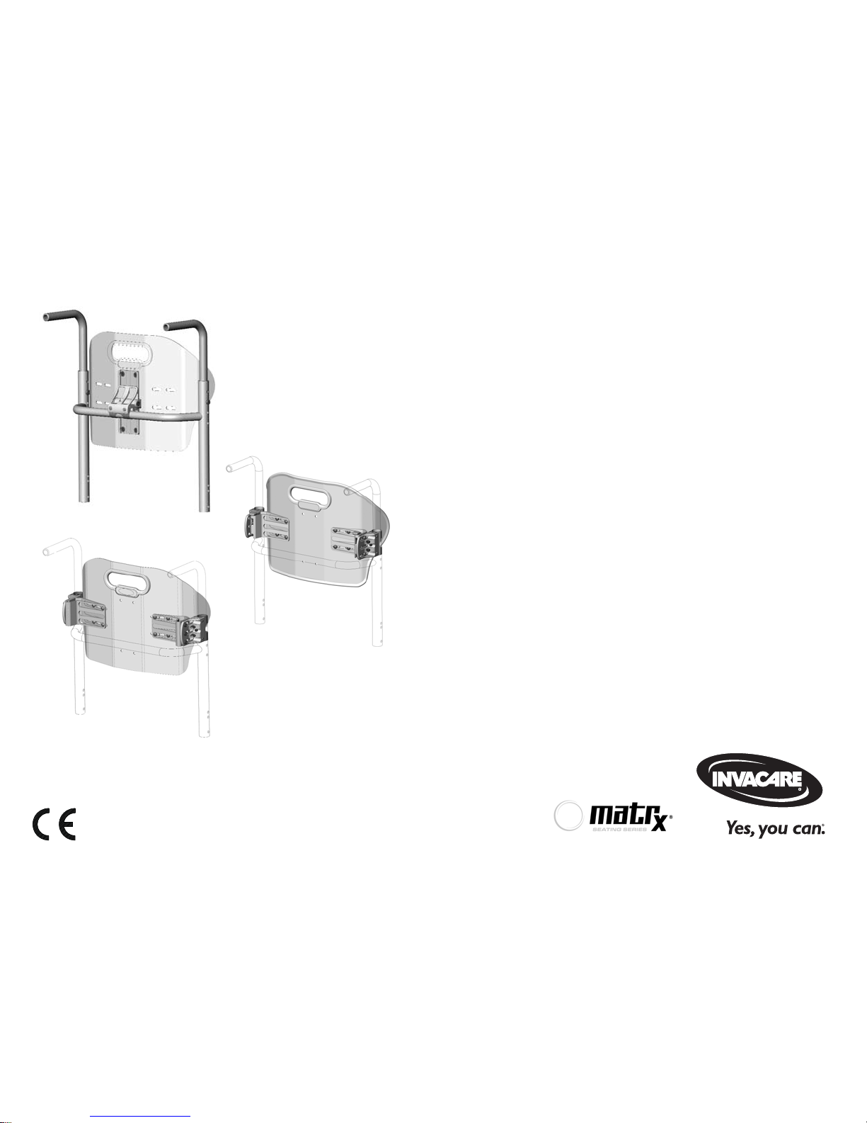
Invacare Matrx MX1
The Invacare Matrx MX1 back is contoured to provide precise orientation within the wheelchair for optimal postural support. The foam is oversized
to provide extra comfort and protection.
The Invacare Matrx MX1 back includes a movable foam lumbar pad that can be installed/inserted behind the existing foam cushion to provide additional
positioning capability. Refer to Installing/Adjusting the Lumbar Support on page 25 for instructions on how to insert and adjust your lumbar support.
WARNING
Warning indicates a potentially hazardous situation which, if not avoided, could result in death or serious injury.
CAUTION
Caution indicates a potentially hazardous situation which, if not avoided, may result in property damage or minor injury or
both.
Gives useful tips, recommendations and information for efficient, trouble-free use.

1 GENERAL
Part No. 1176090
5
Invacare® Matrx® MX1
Outer Cover
The outer cover is made of a mesh material that is moisture resistant and breathable. Regular cleaning and inspection of the outer cover is
recommended. Refer to Cleaning on page 27.
1.3 Limited Warranty
This warranty is extended only to the original purchaser/user of our products.
This warranty gives you specific legal rights and you may also have other legal rights which vary from state to state.
Invacare/Motion Concepts warrants this product to be free from defects in materials and workmanship for two years of use by original purchaser. This
warranty does not apply to punctures, tears or burns, nor to the removable cushion cover. If within such warranty period any such product shall be
proven to be defective, such product shall be repaired or replaced, at Invacare's/Motion Concepts’ option, with refurbished or new parts. This warranty
does not include any labor or shipping charges incurred in replacement part installation or repair of any such product. Product repairs shall not extend
this warranty - coverage for repaired product shall end when this limited warranty terminates. Invacare's/Motion Concepts’ sole obligation and your
exclusive remedy under this warranty shall be limited to such repair and/or replacement.
For warranty service, please contact the dealer from whom you purchased your Invacare/Motion Concepts product. In the event you do not receive
satisfactory warranty service, please write directly to Invacare/Motion Concepts at the address on the back cover. Provide dealer's name, address, model
number, the date of purchase, indicate nature of the defect and, if the product is serialized, indicate the serial number.
Invacare Corporation/Motion Concepts will issue a return authorization. The defective unit or parts must be returned for warranty inspection using the
serial number, when applicable, as identification within thirty (30) days of return authorization date. DO NOT return products to our factory without our
prior consent. C.O.D. shipments will be refused; please prepay shipping charges.
LIMITATIONS AND EXCLUSIONS: THE WARRANTY SHALL NOT APPLY TO PROBLEMS ARISING FROM NORMAL WEAR OR FAILURE TO
ADHERE TO THE ENCLOSED INSTRUCTIONS. IN ADDITION, THE FOREGOING WARRANTY SHALL NOT APPLY TO SERIAL NUMBERED
PRODUCTS IF THE SERIAL NUMBER HAS BEEN REMOVED OR DEFACED; PRODUCTS SUBJECTED TO NEGLIGENCE, ACCIDENT, IMPROPER
OPERATION, MAINTENANCE OR STORAGE; OR PRODUCTS MODIFIED WITHOUT INVACARE'S/MOTION CONCEPTS’ EXPRESS WRITTEN
CONSENT INCLUDING, BUT NOT LIMITED TO: MODIFICATION THROUGH THE USE OF UNAUTHORIZED PARTS OR ATTACHMENTS:
PRODUCTS DAMAGED BY REASON OF REPAIRS MADE TO ANY COMPONENT WITHOUT THE SPECIFIC CONSENT OF INVACARE/MOTION
CONCEPTS; PRODUCTS DAMAGED BY CIRCUMSTANCES BEYOND INVACARE'S/MOTION CONCEPTS’ CONTROL; PRODUCTS REPAIRED BY
ANYONE OTHER THAN AN INVACARE/MOTION CONCEPTS DEALER, SUCH EVALUATION SHALL BE SOLELY DETERMINED BY INVACARE/
MOTION CONCEPTS.
THE FOREGOING WARRANTY IS EXCLUSIVE AND IN LIEU OF ALL OTHER EXPRESS WARRANTIES, IF ANY, INCLUDING THE IMPLIED
WARRANTIES OF MERCHANTABILITY AND FITNESS FOR A PARTICULAR PURPOSE.
IT SHALL NOT EXTEND BEYOND THE DURATION OF THE EXPRESSED WARRANTY PROVIDED HEREIN AND THE REMEDY FOR
VIOLATIONS OF ANY IMPLIED WARRANTY SHALL BE LIMITED TO REPAIR OR REPLACEMENT OF THE DEFECTIVE PRODUCT PURSUANT TO
THE TERMS CONTAINED HEREIN. INVACARE/MOTION CONCEPTS SHALL NOT BE LIABLE FOR ANY CONSEQUENTIAL OR INCIDENTAL
DAMAGES WHATSOEVER. THIS WARRANTY SHALL BE EXTENDED TO COMPLY WITH STATE/PROVINCIAL LAWS AND REQUIREMENTS.

2 SAFETY
Invacare® Matrx® MX1
6
Part No. 1176090
2 Safety
The Safety section contains important information for the safe operation and use of this product.
2.1 General Guidelines
Check all parts for shipping damage before using. In case of damage, DO NOT use the equipment. Contact the Dealer for further instructions.
2.1 Intended Use
The Invacare Matrx MX1 back is designed to provide precise orientation within the wheelchair for optimal postural support.
2.2 Installation Information
WARNING
DO NOT use this product or any available optional equipment without first completely reading and understanding these instructions and
any additional instructional material such as owner’s manuals, service manuals or instruction sheets supplied with this product or optional
equipment. If you are unable to understand the warnings, cautions or instructions, contact a healthcare professional, dealer or technical
personnel before attempting to use this equipment - otherwise, injury or damage may occur.
ACCESSORIES WARNING
Invacare products are specifically designed and manufactured for use in conjunction with Invacare accessories. Accessories designed by
other manufacturers have not been tested by Invacare and are not recommended for use with Invacare products.
!
NOTICE
THE INFORMATION CONTAINED IN THIS DOCUMENT IS SUBJECT TO CHANGE WITHOUT NOTICE.
WARNING
The procedures in this manual should be performed by a qualified technician.
After any adjustments, repair or service and before use, make sure that all attaching component parts are secure.
DO NOT install the Invacare Matrx MX1 assembly onto back canes with an outside diameter greater than 1-inch (25 mm) or less than 3/
4-inch (19 mm). Otherwise, injury or damage may occur.
The mounting position of the Invacare Matrx MX1 is directly related to the chair's stability. Use extreme caution when using a new seating
position.
Ensure the Invacare Matrx MX1 is properly secured to the wheelchair before using. Otherwise injury or damage may occur.

2 SAFETY
Part No. 1176090
7
Invacare® Matrx® MX1
2.3 Operating Information
2.4 Weight Limitation and Model Numbers
WARNING
Skin condition should be checked very frequently after the installation of any new seating system.
Your therapist and physician should be consulted if you have any questions regarding individual limitations and needs.
Working with your therapist, physician, and equipment supplier is the best way to assure that a seating choice matches your individual
needs.
As the needs of the individual become more complex, the seating evaluation becomes more important.
Refer to the chart for the weight limitation and stock model numbers.
RM = Mono Mount (installs onto rigidizer bar)
CF = Dual Mount (installs onto back canes)
*Configured model number: IMX1 (includes Mono Mount, Fixed Dual Mount and Quick Release Dual Mount)
WIDTH HEIGHT WEIGHT LIMIT
23 CM 31 CM 41 CM
36 cm
IMX13623-NH
1545279
IMX13631-NH
1545280
IMX13641-NH
1545281
113 kg
38 cm
IMX13823-NH
1545282
IMX13831-NH
1545283
IMX13841-NH
1545284
41 cm
IMX14123-NH
1545285
IMX14131-NH
1545286
IMX14141-NH
1545287
43 cm
IMX14323-NH
1545288
IMX14331-NH
1545289
IMX14341-NH
1545290
46 cm
IMX14623-NH
1545314
IMX14631-NH
1545315
IMX14641-NH
1545316
14 in (36 cm) - 18 in (46 cm) IMX1*

3 MONO MOUNT
Invacare® Matrx® MX1
8
Part No. 1176090
3 Mono Mount
3.1 Installation Overview
Included Items
• Back Shell with Foam and Cover
• Rigidizer Bracket
• Tracking Plate
• Band Clamp Assemblies
3.2 Tools Required
• Tape measure/ruler
• 4mm hex key (provided)
3.3 Before Installation
Hardware is sold separately.
If any of the hardware is missing or misplaced, please
contact our customer service department and
arrangements will be made to send you the necessary
replacements. Refer to Contact Information on page 355.
WARNING
Before beginning the installation process, please fully
read through the instructions to understand the steps
and adjustments involved. If you have any questions or
concerns during the installation process, please contact
our customer service department.
3 MONO MOUNT
Part No. 1176090
9
Invacare® Matrx® MX1
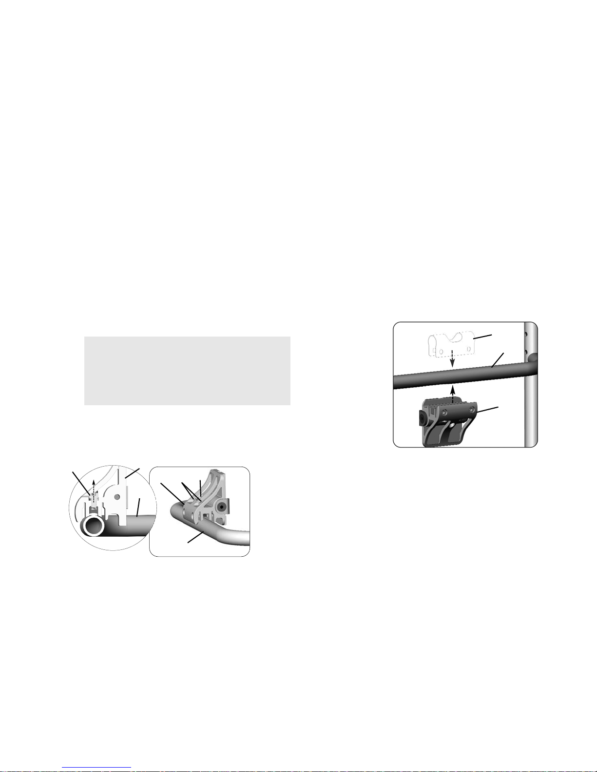
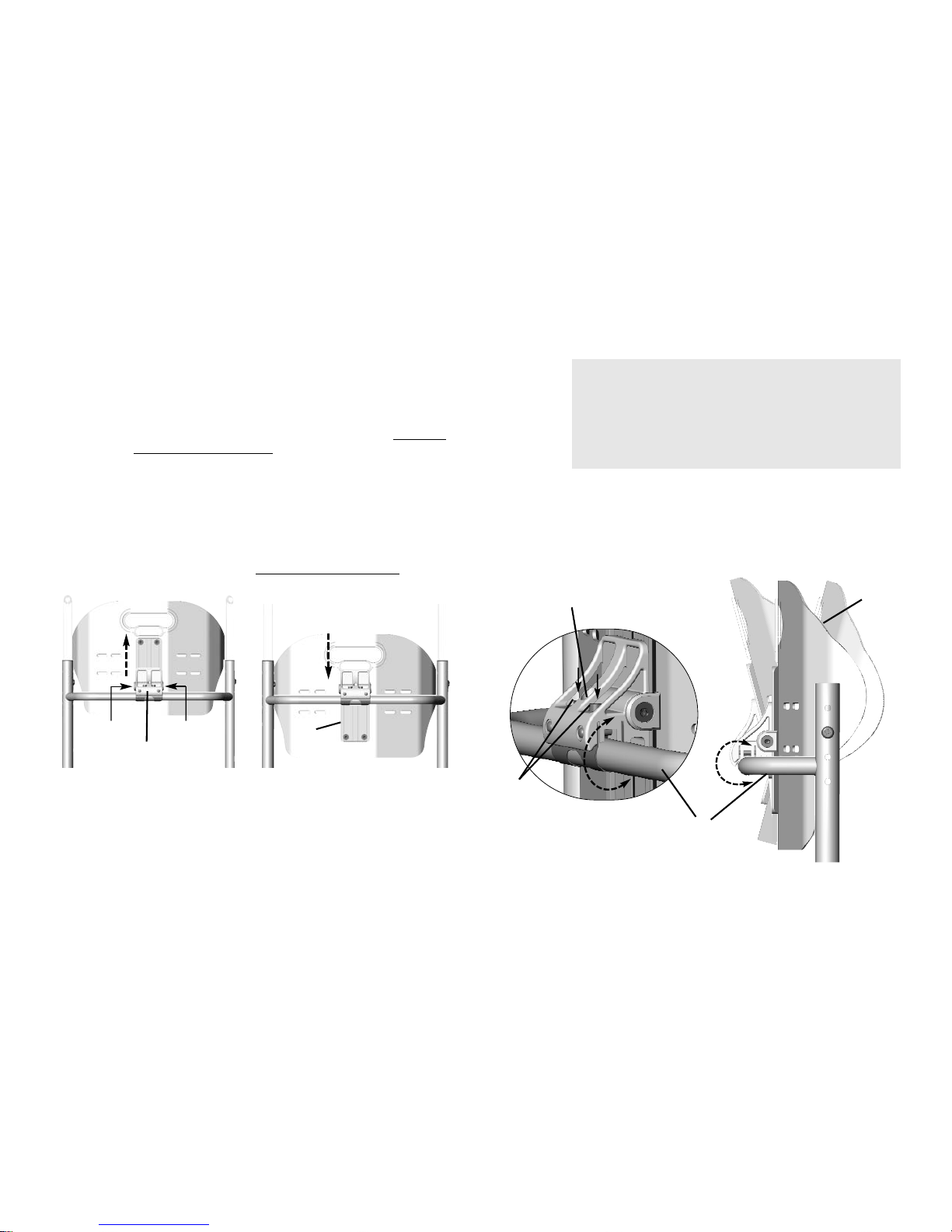
3.4 Installing the Mounting Hardware
1. Remove any existing wheelchair back, back upholstery or back cane
hardware. Refer to the user manual that came with the wheelchair
or back upholstery.
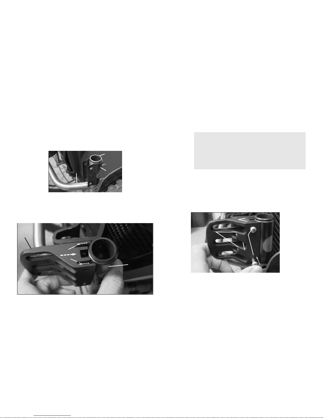
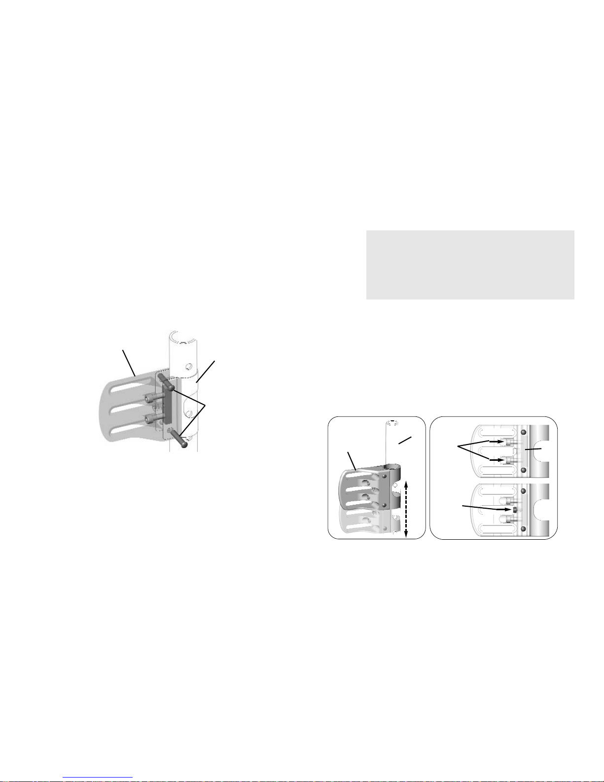
2. Loosen the compression bar hardware A inside the rigidizer
bracket B.
3. Install the band clamp E onto the rigidizer bar D in the desired
orientation.
4. Position the rigidizer bracket B at a 45° angle to the band clamp.
5. Align the edges of the clamp with the corresponding slots F in the
rigidizer bracket.
6. Carefully slide the rigidizer bracket onto the band clamp.
7. Ensure the clamp is fully engaged in the slots in the rigidizer bracket.
8. Insert the two locking pins G into the rigidizer bracket to hold the
band clamp in place.
9. Ensure the pins are fully inserted into the rigidizer bracket.
For ease of installation, install the mounting bracket
hardware onto the rigidizer bar first. The MX1 back
cushion can be installed onto the rigidizer bracket after
the mounting hardware is installed.
WARNING
DO NOT adjust the center screw in the rigidizer
bracket. The center screw C is designed only to hold
the compression bar in place during installation.
Adjusting this screw may prevent the compression bar
from tightening properly onto the back cane.
The compression bar hardware must be loosened to
ensure the rigidizer bracket rests flush against the rigidizer
bar D.
The rigidizer bar is shown in the illustration for reference
only.
A
B
D
B
A
D
2
C
The rigidizer bracket is secured to the rigidizer bar via a
band clamp. Each hardware kit comes equipped with
one of three differently sized band clamps.
9-inch (23 cm) Tall MX1 Back Cushions Only:
In order to optimize the available height adjustment on the
back cushion, it may be necessary to invert the rigidizer
bracket during installation as shown below.
B
E
D
3 MONO MOUNT
Invacare® Matrx® MX1
10
Part No. 1176090
10. Center the bracket between the back canes.
11. Tighten the compression bar hardware A just snug enough to hold
the bracket assembly in place.
12. Install the tracking plate. Refer to Installing the Tracking Plate on
the Back Shell on page 11.
The pins should slide into position with little effort. If the
pins are difficult to insert, verify that the band clamp is
properly centered and fully seated inside the slots of the
rigidizer bracket.
B
D
E
G
STANDARD
INSTALLATION
3
4
5
8
F
F
G
D
E
OPTIONAL INVERTED POSITION
FOR 9” (23 CM) TALL BACKS
B
3
WARNING
DO NOT adjust the center screw in the rigidizer
bracket. The center screw B is designed only to hold
the compression bar in place during installation.
Adjusting this screw may prevent the compression bar
from tightening properly onto the back cane.
Do not fully tighten the compression bar at this time.
A
11
A
B
3 MONO MOUNT
Part No. 1176090
11
Invacare® Matrx® MX1
3.5 Installing the Tracking Plate on the Back Shell
1. Disengage the cover (not shown) from the top and bottom of the
back shell A.
2. Remove the cushion and cover from the back shell.
3. Secure the tracking plate B to the back using the four screws C,
washers (not shown) and nuts (not shown). Tighten securely.
4. Secure the cushion and cover to the top of the back shell.
5. Secure the cushion and cover to the inside of the back shell.
6. Install the back shell.
3.6 Installing the Back Shell onto the Mounting
Hardware
1. If necessary, disengage the outer cover hook and loop strip at the
bottom rear of the back (not shown).
2. Loosen the two locking wedge washers A on each side of the
rigidizer bracket B.
3. Align the notched channel C in the bracket with the corresponding
raised area D on the mounting rail E.
4. Slide the mounting rail onto the rigidizer bracket.
5. Adjust the back cushion to the desired height along the channels in
the mounting rail.
6. Tighten the locking wedge washers on each side of the rigidizer
bracket to secure the back into position.
7. Adjust the back height. Refer to Adjusting the Back Height
on
page 12.
A
B
C
A
A
B
B
A
C
D
E
TOP VIEW
2 & 6
3-5
3 MONO MOUNT
Invacare® Matrx® MX1
12
Part No. 1176090
3.7 Adjusting the Back Height
1. Loosen the two locking wedge washers A on each side of the
rigidizer bracket B.
2. Adjust the back cushion to the desired height along the channels in
the mounting rail C.
3. Tighten the locking wedge washers on each side of the rigidizer
bracket to secure the back into position.
4. Adjust the back angle. Refer to Adjusting the Back Angle
.
\
3.8 Adjusting the Back Angle
1. Loosen the compression bar hardware A.
2. Rotate the back cushion B around the rigidizer bar C to the
desired position.
3. Tighten the compression bar hardware to secure the back cushion
in position.
4. Verify that all mounting hardware is properly tightened and the
back is held firmly in place on the rigidizer bar.
9-inch (23 cm) Tall MX1 Back Cushions Only:
In order to optimize the available height adjustment on
the back cushion, it may be necessary to invert the
rigidizer bracket during installation. Refer to Installing
the Mounting Hardware on page 9.
A
A
2
2
B
C
WARNING
DO NOT adjust the center screw in the rigidizer
bracket. The center screw D is designed only to hold
the compression bar in place during installation.
Adjusting this screw may prevent the compression bar
from tightening properly onto the back cane.
When tightening the compression bar hardware, alternate
back and forth between the two mounting screws to
ensure the compression bar is fully secured.
A
B
C
1 & 3
D
3 MONO MOUNT
Part No. 1176090
13
Invacare® Matrx® MX1
3.9 Removing the Mono Mount Hardware
1. Open the cushion cover at the bottom of the back cushion (not
shown).
2. Loosen the locking wedge washers A on either side of the rigidizer
bracket B.
3. Slide the back cushion C upward until the mounting rail D is
disengaged from the rigidizer bracket.
4. Loosen the compression bar hardware E to loosen the band clamp
F.
5. Use a hex key H to push out the locking pins I from the rigidizer
bracket.
6. Separate the rigidizer bracket from the band clamp.
WARNING
DO NOT adjust the center screw in the rigidizer
bracket. The center screw G is designed only to hold
the compression bar in place during installation.
Adjusting this screw may prevent the compression bar
from tightening properly onto the back cane.
A
A
B
C
D
E
F
H
I
2
3
4
5
6
G
4 FIXED DUAL MOUNT
Invacare® Matrx® MX1
14
Part No. 1176090
4 Fixed Dual Mount
4.1 Installation Overview
Included Items
• Back Shell with Foam and Cover
• Angle Adjustable Brackets
• Band Clamp Assemblies
4.2 Tools Required
• Tape measure/ruler
• 4mm hex key (provided)
4.3 Before Installation
If any of the hardware is missing or misplaced, please
contact our customer service department and
arrangements will be made to send you the necessary
replacements. Refer to Contact Information on page 355.
WARNING
Before beginning the installation process, please fully
read through the instructions to understand the steps
and adjustments involved. If you have any questions or
concerns during the installation process, please contact
our customer service department.
4 FIXED DUAL MOUNT
Part No. 1176090
15
Invacare® Matrx® MX1
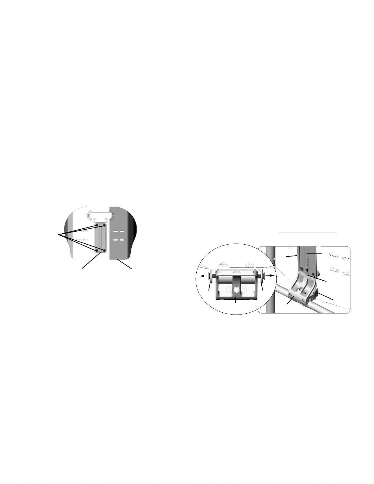
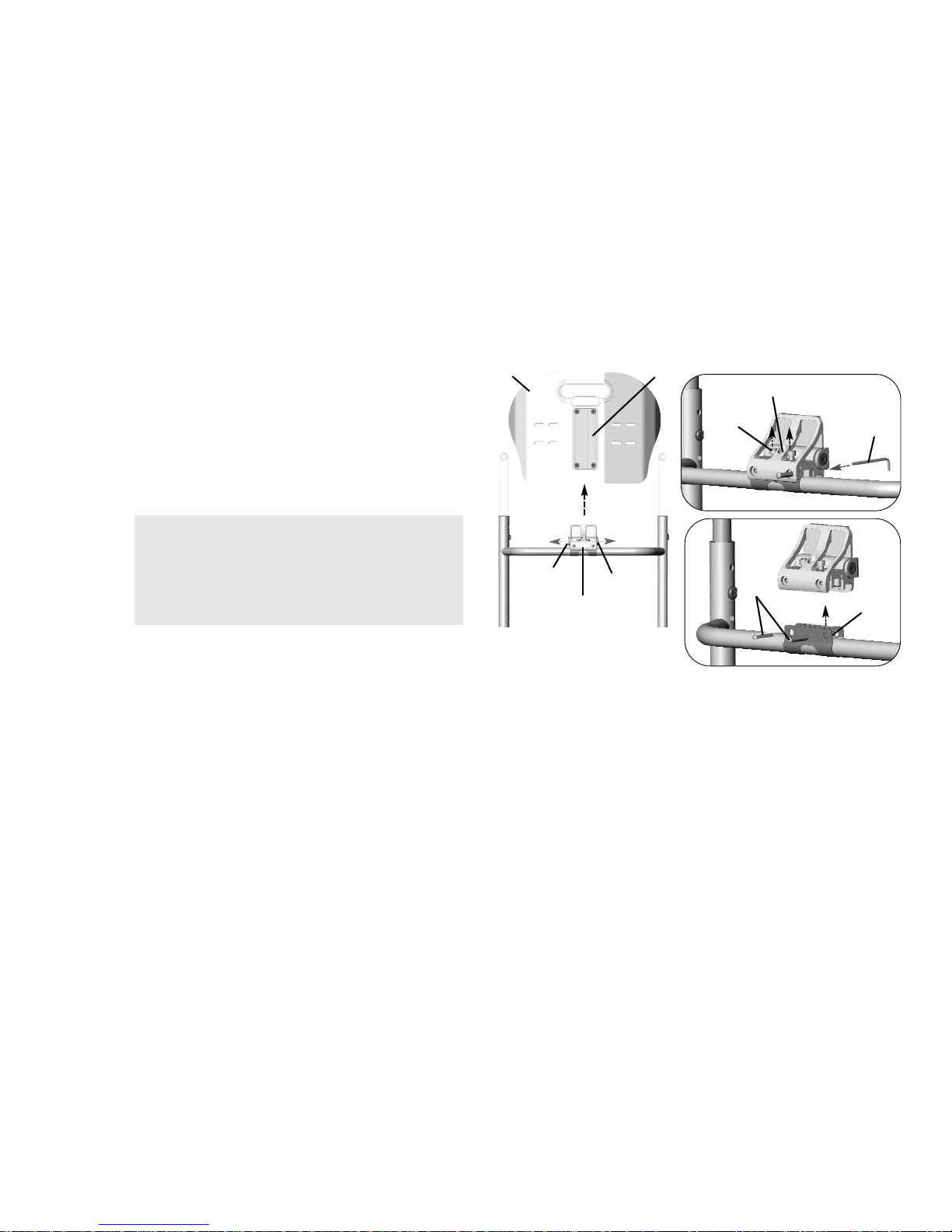
4.4 Installing the Angle Adjustable Brackets onto the
Back Shell
1. Remove any existing wheelchair back, back upholstery or back cane
hardware.
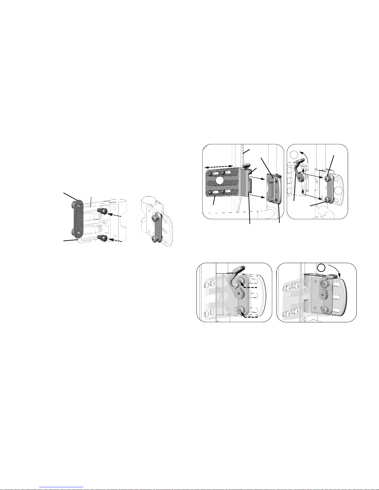
2. Remove the four hex screws A and washers (not shown) securing
the two backing plates B to the angle adjustable bracket C.
3. Align the angle adjustable bracket with the slots D on one side of
the back shell E.
4. Place the four washers onto the hex screws.
5. Loosely attach the angle adjustable bracket to the back shell using
the two backing plates, four hex screws and four washers. Do not
tighten the hex screws at this time.
6. Repeat STEPS 2-5 for the other bracket.
4.5 Clamp Body Adjustment
The clamp body is pre-installed onto the angle adjustable bracket at the
factory.
The clamp body C is secured to the angle adjustable bracket D via three
screws A, three washers (not shown) and a backing plate B.
For most typical installations, the clamp body can remain secured in place
on the angle adjustable bracket in order to complete the installation of
the band clamp (refer to Installing the Band Clamps
).
Where necessary, the clamp body may be repositioned by performing
this procedure.
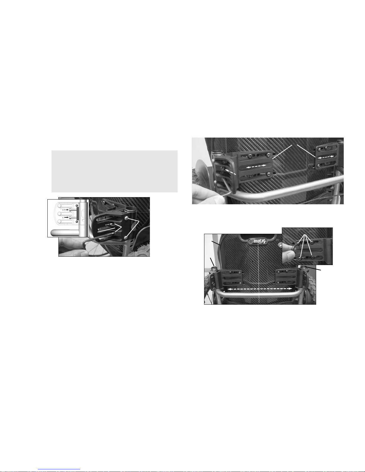
1. Loosen the three screws A.
2. Slide the clamp body C along the slot of the angle adjustable
bracket. Refer to Adjusting the Back Angle and Back Depth
on
page 18.
3. Repeat STEPS 1-3 for the opposite side.
The angle adjustable bracket should be oriented with the
four slots F against the back shell.
A
B
C
E
F
D
After any adjustment, re-tighten the three screws to
secure the clamp body to the angle adjustable bracket.
D
C
A
B
4 FIXED DUAL MOUNT
Invacare® Matrx® MX1
16
Part No. 1176090
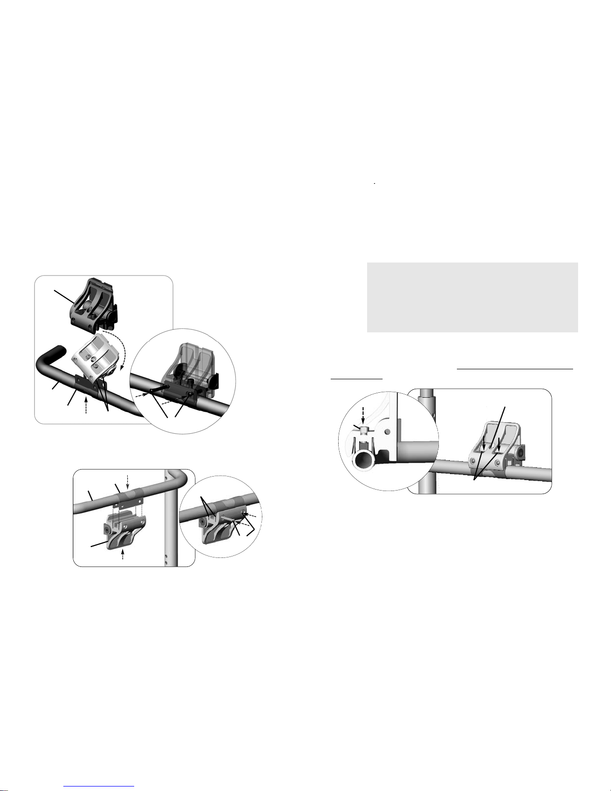
4.6 Installing the Band Clamps
1. Install the two band clamps A onto the back canes B of the
wheelchair.
4.7 Installing the Back
1. Align and insert the tabs A on the band clamp B with the slots C
in the clamp body D.
2. Ensure the band clamp is fully inserted into the clamp body.
3. Loosen the compression bar hardware E, so the clamp body rests
flush against the back cane.
4. Insert the two locking pins G into the clamp body to lock the band
clamp in position.
5. Ensure both locking pins are fully inserted.
\
Allow the band clamps to rest on the rigidizer bar C.
A
C
B
A
B
C
D
WARNING
DO NOT adjust the center screw in the clamp body.
The center screw F is designed only to hold the
compression bar in place during installation. Adjusting
this screw may prevent the compression bar from
tightening properly onto the back cane.
The pins should slide into position with little effort. If the
pins are difficult to insert, verify that the band clamp is
properly centered and fully seated inside the slots G of
the clamp body.
E
G
H
F
4 FIXED DUAL MOUNT
Part No. 1176090
17
Invacare® Matrx® MX1
6. Tighten the compression bar hardware E to hold the locking pins
G in place. Do not fully tighten the hardware at this time.
7. Repeat STEPS 1-6 to install the back onto the remaining band clamp.
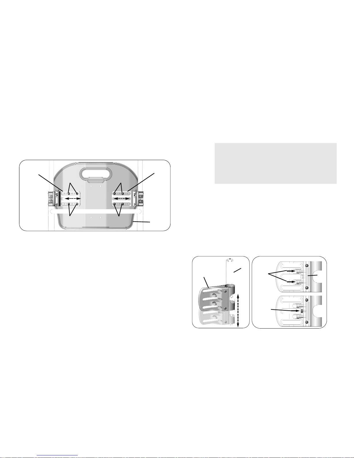
8. Adjust the back shell J so it is centered between the back canes K.
9. Tighten the eight screws L securing the angle adjustable brackets
I to the back shell.
WARNING
DO NOT adjust the center screw in the clamp body.
The center screw F is designed only to hold the
compression bar in place during installation. Adjusting
this screw may prevent the compression bar from
tightening properly onto the back cane.
It may be necessary to slide the angle adjustable brackets
I to allow the clamp body to properly align with the band
clamp.
E
G
F
I
I
J
K
L
4 FIXED DUAL MOUNT
Invacare® Matrx® MX1
18
Part No. 1176090
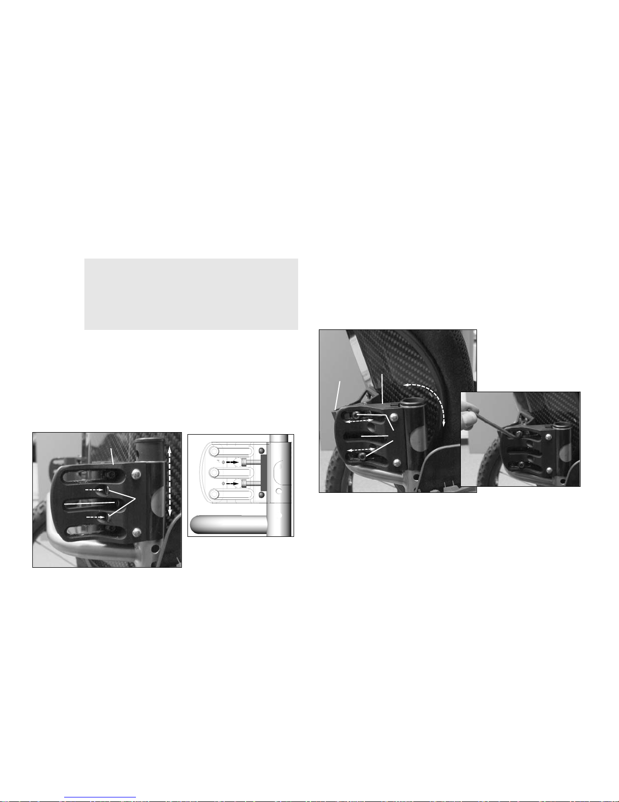
4.8 Adjusting the Back Height
1. Loosen the compression bar hardware A.
2. Adjust the back to the desired height.
3. Tighten the compression bar hardware to secure the clamp bodies
C in place.
4.9 Adjusting the Back Angle and Back Depth
1. Loosen the screws A on the side of both clamp bodies B.
2. Adjust the angle adjustable brackets C in the clamp bodies to
achieve the desired back angle and back depth.
3. Tighten the screws on both clamp bodies to secure the back into
position.
4.10 After Installation
1. Verify that all mounting hardware is fully tightened.
2. Ensure that the back is securely attached to the wheelchair.
WARNING
DO NOT adjust the center screw in the clamp body.
The center screw B is designed only to hold the
compression bar in place during installation. Adjusting
this screw may prevent the compression bar from
tightening properly onto the back cane.
Height adjustments must be made equally on both back
canes.
When re-tightening the compression bar hardware,
alternate back and forth between the screws until the
compression bar is fully secured.
C
A
B
Angle and depth adjustments must be made equally on
both sides.
A
B
C

5 QUICK RELEASE DUAL MOUNT
Part No. 1176090
19
Invacare® Matrx® MX1
5 Quick Release Dual Mount
5.1 Installation Overview
Included Items
• Back Shell with Foam and Cover
• Adjustable Mounting Bracket
• Band Clamps
5.2 Tools Required
• Tape measure/ruler
• 4mm hex key (provided)
5.3 Before Installation
If any of the hardware is missing or misplaced, please
contact our customer service department and
arrangements will be made to send you the necessary
replacements. Refer to Contact Information on page 355.
WARNING
Before beginning the installation process, please fully
read through the instructions to understand the steps
and adjustments involved. If you have any questions or
concerns during the installation process, please contact
our customer service department.
5 QUICK RELEASE DUAL MOUNT
Invacare® Matrx® MX1
20
Part No. 1176090
5.4 Installing the Adjustable Mounting Brackets onto
the Back Shell
1. Remove any existing wheelchair back, back upholstery or back cane
hardware.
2. Remove the four hex screws A and washers (not shown) securing
the two backing plates B to the adjustable mounting bracket C.
3. Align the adjustable mounting bracket with the slots D on one side
of the back shell E.
4. Place the four washers onto the hex screws.
5. Loosely attach the adjustable mounting bracket to the back shell
using the two backing plates, four hex screws and four washers. Do
not tighten the hex screws at this time.
6. Repeat STEPS 2-5 for the other bracket.
5.5 Loosening the Compression Bar
1. Loosen the two screws A securing the compression bar B to the
clamp body C.
5.6 Installing the Band Clamps
1. Install the two band clamps A onto the back canes B of the
wheelchair.
2. Install the clamp body C onto the band clamp at a 45° angle by
aligning the edges of the clamp with the corresponding slots D in
the clamp body.
3. Carefully slide the two components together.
4. Ensure that the clamp is fully inserted inside the slots on the clamp
body.
The adjustable mounting bracket should be oriented with
the four slots F against the back shell.
A
B
C
E
F
D
Loosening the compression bar allows the clamp body to
sit flush against the back cane D prior to installation
(Detail A).
D
C
A
B
DETAIL A
B
D
A
B
D
C
5 QUICK RELEASE DUAL MOUNT
Part No. 1176090
21
Invacare® Matrx® MX1
5.7 Securing the Clamp Body to the Band Clamp
1. Insert the two locking pins A into the clamp body B to secure it to
the band clamp C.
2. Ensure the pins are fully seated into the clamp body.
3. Repeat STEPS 1-2 for the opposite side.
5.8 Securing the Clamp Body Assembly to the Back
Cane
1. Slide the clamp body assembly A to the desired height on the back
cane B (Detail A).
2. Hold the clamp body assembly perpendicular to the back of the
wheelchair (parallel to the rear wheel).
3. Tighten the two screws D to push the compression bar E against
the back cane and secure the clamp body in place.
4. Repeat STEPS 1-3 for the opposite clamp body assembly.
The pins should slide into position with little effort. If pins
are difficult to insert, verify that the band clamp is properly
centered and fully inserted inside the slots of the mounting
bracket.
B
C
A
WARNING
DO NOT adjust the center screw in the clamp body.
The center screw C is designed only to hold the
compression bar in place during installation (Detail B).
Adjusting this screw may prevent the compression bar
from tightening properly onto the back cane.
When re-tightening the compression bar hardware,
alternate back and forth between the screws until the
compression bar is fully secured.
The clamp bodies must be at the same height on each side
of the back cane. Otherwise the back may not install
correctly or at all.
DETAIL A DETAIL B
A
B
D
C
E
5 QUICK RELEASE DUAL MOUNT
Invacare® Matrx® MX1
22
Part No. 1176090
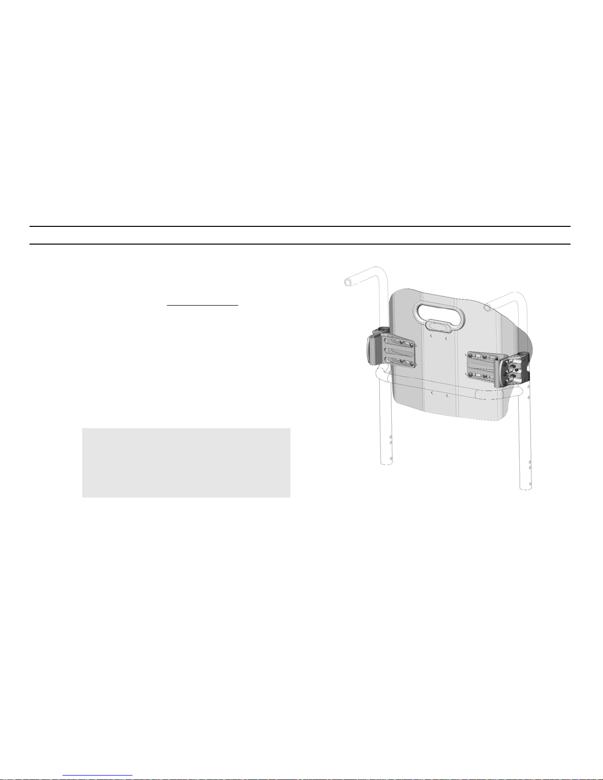
5.9 Installing the Back
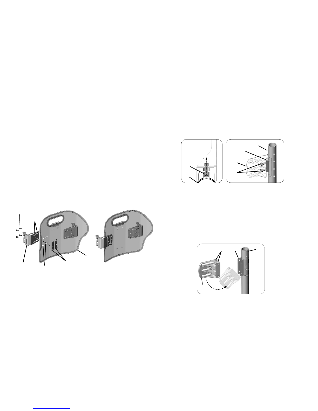
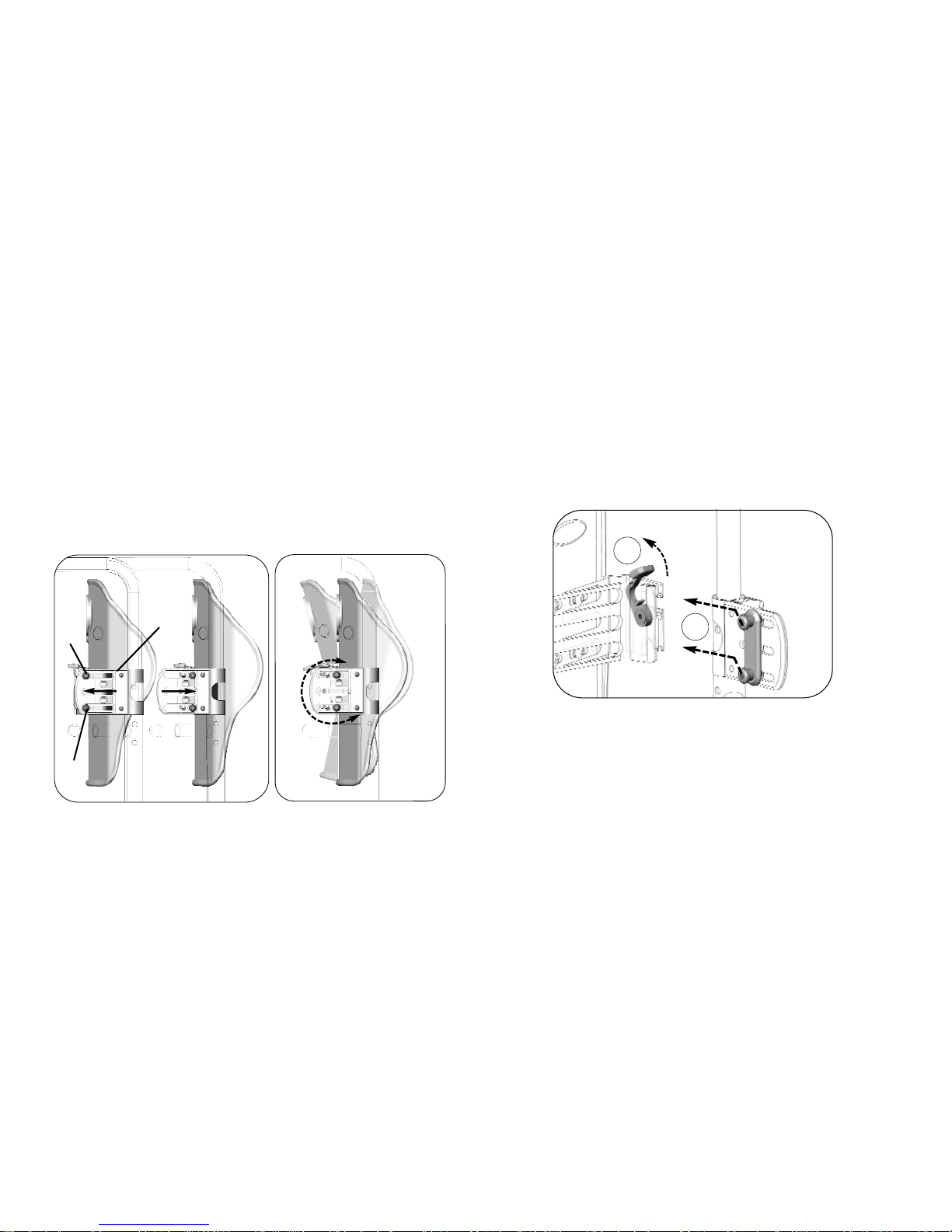
1. Loosen the four mounting screws securing the adjustable mounting
bracket D to the back pan E.
2. Adjust the width of the adjustable mounting bracket so that it aligns
with the mounting pin assembly on the clamp body.
3. Lift the lever F on the adjustable mounting bracket to unlock it.
4. Insert the upper and lower pins G into the notches H in the
adjustable mounting bracket.
5. Push down on the back pan to ensure the mounting pins are
properly seated inside the notched recess of the adjustable
mounting bracket.
6. Press the lever down to lock the back pan into place.
The instructions in this section apply to both sets of
mounting hardware.
The right side is pictured in the figures in this procedure.
The mounting pin assembly A is secured to the slots B of
the clamp body C.
A
INSIDE VIEW
B
C
2
3
4
C
A
F
D
E
H
G
H
G
6
5 QUICK RELEASE DUAL MOUNT
Part No. 1176090
23
Invacare® Matrx® MX1
7. Adjust the back position in the slots of the adjustable mounting
brackets to center the back pan E between the back canes.
8. Tighten the eight hex screws H securing the adjustable mounting
brackets D to the back pan.
5.10 Adjusting the Back Height
1. Loosen the compression bar hardware C on both back canes D.
2. Adjust the back to the desired height (Detail A).
3. Tighten the compression bar hardware to secure the clamp bodies
E in place.
D
D
H
H
H
H
E
WARNING
DO NOT adjust the center screw in the clamp body.
The center screw A is designed only to hold the
compression bar B in place during installation (Detail
B). Adjusting this screw may prevent the compression
bar from tightening properly onto the back cane.
Height adjustments must be made equally on both back
canes.
When re-tightening the compression bar hardware,
alternate back and forth between the screws until the
compression bar is fully secured.
DETAIL A DETAIL B
E
D
C
A
B
5 QUICK RELEASE DUAL MOUNT
Invacare® Matrx® MX1
24
Part No. 1176090
5.11 Adjusting the Back Angle and Back Depth
1. Loosen the screws A in the mounting pin assembly of both clamp
bodies B.
2. Adjust the position of the mounting pin assembly via the slots in the
clamp bodies to achieve the desired back depth (Detail A) and back
angle (Detail B).
3. Tighten the screws on both clamp bodies to secure the back into
position.
5.12 After Installation
1. Verify that all mounting hardware is fully tightened.
2. Ensure that the back is securely attached to the wheelchair.
5.13 Removing the Back Cushion
1. Unlock the levers on the adjustable mounting brackets.
2. Lift the back cushion up and forward to disengage it from the
mounting pins.
Angle and depth adjustments must be made equally on
both sides.
A
A
B
Detail A Detail B
1
2
6 OPTIONS
Part No. 1176090
25
Invacare® Matrx® MX1
6 Options
6.1 Installing/Adjusting the Lumbar Support
1. To access the lumbar support, open the hook and loop fastening strips
on the outer cover A at the bottom rear of the back shell.
2. The foam lumbar support B is installed inside the Invacare Matrx
MX1 cover between the foam back cushion C and the back shell D.
3. The lumbar support can be adjusted to any desired height/position.
4. Refasten the cover onto the back pan.
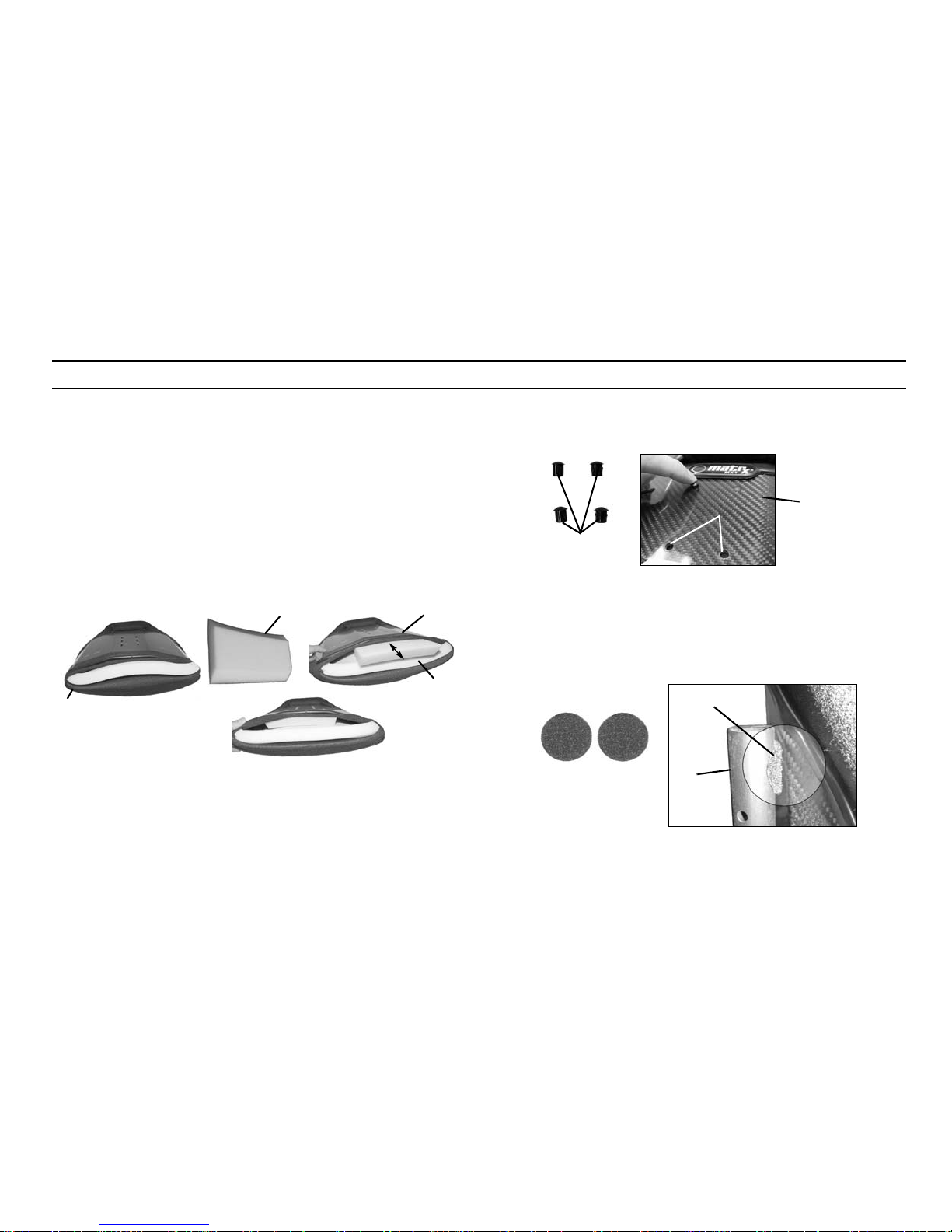
6.2 Plug Inserts
Optional plug inserts (Model DP-250) A may be used to fill unused
mounting holes B on the back shell C.
6.3 Adhesive Pads
Adhesive pads A are available to protect the back shell B from
scratches.
1. Peel the protective paper off of the back of the adhesive pad.
2. Install the adhesive pad between the back shell and the back cane C
or other wheelchair component that may rub against the back shell.
The Lumbar Support is a pre-fabricated foam insert that
provides lower back support for additional comfort. The
position of the lumbar insert can be adjusted inside the
Invacare Matrx MX1 cover, or it may be removed if no
lumbar support is desired
C
A
D
B
B
A
C
A
A
B
C
6 OPTIONS
Invacare® Matrx® MX1
26
Part No. 1176090
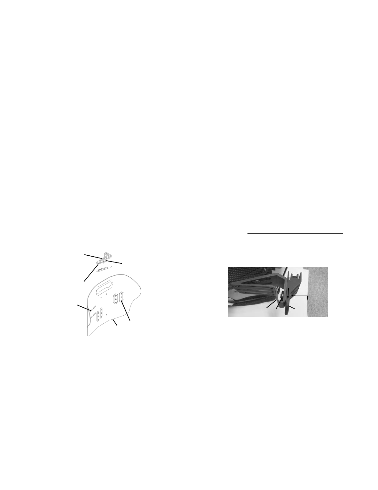
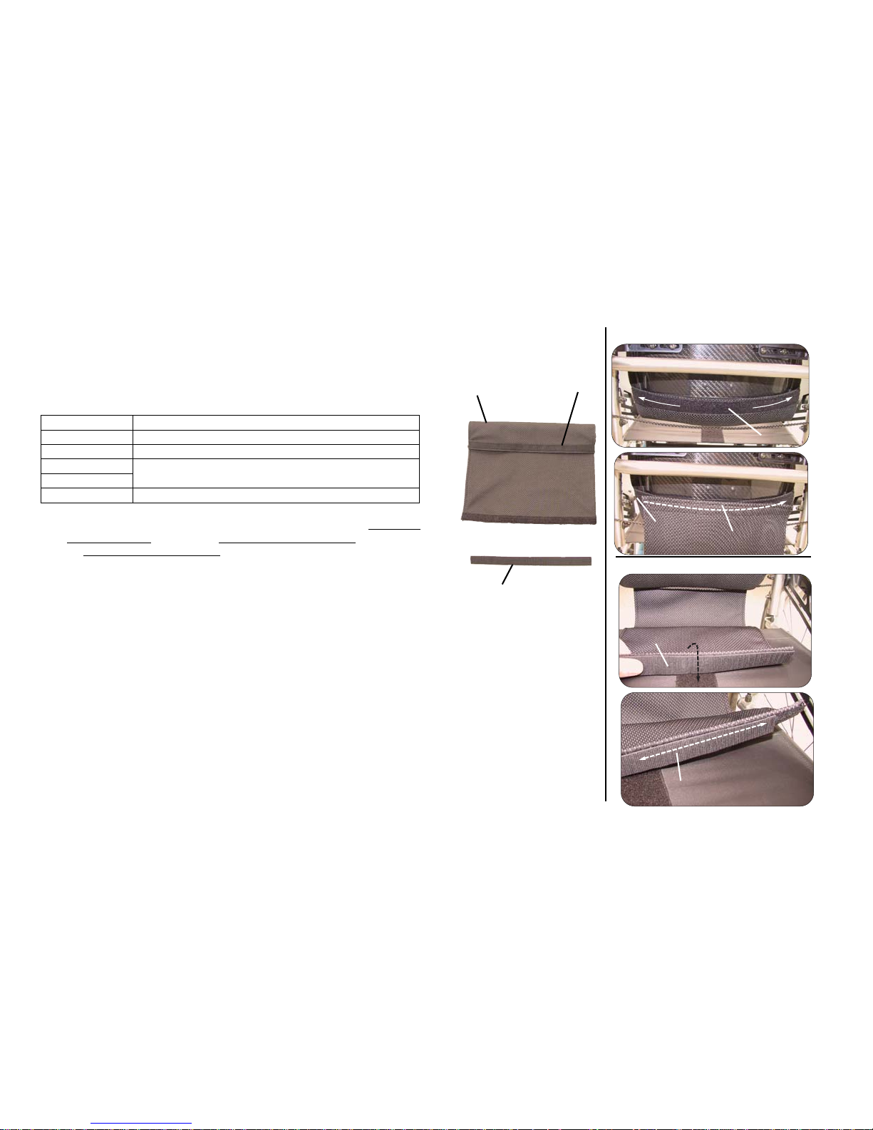
6.4 Installing the Optional Privacy Flap
Privacy flaps A are available (sold separately) for use with all standard
sized MX1 backs. All standard sized backs come with a pre-sewn loop
strip across the bottom rear of the cushion cover B for installation of
the privacy flap.
Refer to the chart for proper sizing of the privacy flap for the MX1 back.
1. If installed, remove the seat cushion.
2. Ensure the back is adjusted to the desired height. Refer to Adjusting
the Back Height on page 12, Adjusting the Back Height on page 19
or Adjusting the Back Height on page 26.
3. Position the wheelchair in front of you so the back is facing you.
4. Align the hook strip C on the privacy flap with the loop strip sewn
on to the bottom rear of the back cover.
5. Pull the opposite end of the privacy flap through the gap between
the back and the wheelchair seat D.
6. Secure the loop strip E on the opposite end of the privacy flap to
the fastening strip on the wheelchair seat.
WIDTH PRIVACY FLAP
14 in (36 cm) 1551799: 10” x 16” (26 cm x 41 cm)
15 in (38 cm) 1551800: 13” x 16” (33 cm x 41 cm)
16 in (41 cm)
1551903: 15” x 16” (38 cm x 41 cm)
17 in (43 cm)
18 in (46 cm) 1551904: 17” x 16” (43 cm x 41 cm)
The fastening strip pre-installed on the wheelchair seat pan
or sling upholstery may be either a hook strip or a loop
strip. It may be necessary to install the the double sided
hook strip F onto the privacy flap to secure it to the seat.
A
Detail A
B
C
D
A
C
Rear View
Front View
1-3
D
E
F
F
4
5
6
B
A
A
D

7 MAINTENANCE
Part No. 1176090
27
Invacare® Matrx® MX1
7 Maintenance
7.1 Cleaning
General Cleaning
1. Wipe the outer cover with a damp cloth when necessary.
Laundering
1. Release the hook and loop fasteners securing the back cushion
cover. The hook and loop fasteners are located on the top and
bottom edge and inside of the back shell.
2. Remove the foam cushion.
3. Remove the lumbar support. Refer to Installing/Adjusting the
Lumbar Support on page 19.
4. Remove the cover from the back shell.
5. Follow the washing instructions on the cover.
6. Allow the cover to fully dry.
7. Install the cover onto the back shell.
8. Insert the foam cushion into the cover.
9. Ensure the foam cushion is fully inserted and the perimeter of the
foam is aligned with the cover seams.
10. Install the lumbar support. Refer to Installing/Adjusting the Lumbar
Support on page 19.
7.2 Inspection
Visually inspect parts including hardware, brackets, upholstery materials,
foams (if accessible), and plastics, for deformation, corrosion, breakage,
wear or compression.
7.3 Reuse
WARNING
Check ALL fasteners weekly to ensure that mechanical
connections and attaching hardware are tightened
securely - otherwise injury or damage may occur.
DO NOT continue to use this product if problems are
discovered. Corrective maintenance can be performed at
or arranged through your equipment supplier.
WARNING: Risk of Injury
Always have a dealer inspect the product for damage
before transferring the product to a different user. If any
damage is found, DO NOT use the product. Otherwise
injury may occur.

Invacare® Matrx® MX1
28
RЩf. 1176090
1 GÉNÉRALITÉS 29
Pictogrammes.......................................................................................................... 29
Aperçu ...................................................................................................................... 29
Informations importantes.............................................................................. 29
Invacare Matrx MX1....................................................................................... 29
Housse extérieure .......................................................................................... 30
Garantie limitée...................................................................................................... 30
2 SÉCURITÉ 31
Directives générales .............................................................................................. 31
Utilisation conforme.............................................................................................. 31
Informations d’installation .................................................................................... 32
Informations de fonctionnement ........................................................................ 32
Restriction de poids et références des modèles ............................................ 33
3 FIXATION CENTRALE 34
Aperçu de l’installation ......................................................................................... 34
Eléments inclus................................................................................................. 34
Outils requis............................................................................................................ 34
Avant l’installation.................................................................................................. 34
Installation du matériel de fixation..................................................................... 35
Installation de la plaque de suivi sur la coquille du dossier ..........................37
Installation de la coquille de dossier sur le matériel de fixation .................38
Réglage de la hauteur du dossier........................................................................ 38
Réglage de la hauteur du dossier........................................................................ 39
Dépose du matériel de fixation du fixation centrale ..................................... 40
4 FIXATIONS LATÉRALES 41
Aperçu de l’installation ......................................................................................... 41
Eléments inclus................................................................................................. 41
Outils requis............................................................................................................ 41
Avant l’installation.................................................................................................. 41
Installation des brides réglables d’angle sur la coquille du dossier ............. 42
Ajustement du corps de collier .......................................................................... 42
Installation des colliers.......................................................................................... 43
Installation du dossier ............................................................................................43
Réglage de la hauteur du dossier ........................................................................45
Réglage de l’angle et de la profondeur du dossier ..........................................45
Après l’installation ..................................................................................................45
5 FIXATIONS LATÉRALES À DÉVERROUILLAGE
RAPIDE 46
Aperçu de l’installation ..........................................................................................46
Eléments inclus .................................................................................................46
Outils requis.............................................................................................................46
Avant l’installation...................................................................................................46
Installation des brides de fixation réglables sur la coquille de dossier.......47
Desserrage de la barre de compression............................................................47
Installation des colliers...........................................................................................48
Fixation du corps de collier à la collier pour fixation ....................................48
Fixation de l'ensemble de corps de collier à la canne de dossier................49
Installation du dossier ............................................................................................50
Réglage de la hauteur du dossier ........................................................................51
Réglage de l’angle et de la profondeur du dossier ..........................................52
Après l’installation ..................................................................................................52
Retrait du coussin de dossier...............................................................................52
6 OPTIONS 53
Installation/Ajustement du soutien lombaire....................................................53
Capuchons de finition ............................................................................................53
Tampons adhésifs....................................................................................................53
Installation du bavette en option.........................................................................54
7 MAINTENANCE 55
Nettoyage.................................................................................................................55
Nettoyage général............................................................................................55
Lavage .................................................................................................................55
Examen......................................................................................................................55
Réutilisation..............................................................................................................55
Manuel d’utilisation
Ce manuel DOIT être remis à l’utilisateur du produit.
AVANT l’utilisation du produit, lisez ce manuel et conservez-le pour référence.
Invacare® Matrx®
MX1

RЩf. 1176090
29
Invacare® Matrx® MX1
1 GÉNÉRALITÉS
1 Généralités
1.1 Pictogrammes
Les mots d’avertissement utilisés dans le présent manuel s’appliquent aux risques ou aux pratiques dangereuses qui pourraient provoquer des
blessures ou des dommages matériels. Voir les informations ci-dessous pour la définition des mots d’avertissement.
1.2 Aperçu
Informations importantes
La meilleure façon d’éviter les problèmes liés aux escarres est d’en comprendre les causes et votre rôle dans un programme de soins dermatologiques.
Demandez l’avis de votre thérapeute ou de votre médecin si vous avez des questions concernant vos restrictions et besoins individuels.
Tous les coussins doivent être choisis avec soin. La collaboration avec votre thérapeute et votre médecin constitue la meilleure façon de s’assurer
qu’un coussin correspond bien à vos besoins.
Plus les besoins individuels sont complexes, plus le choix du coussin est important.
Invacare Matrx MX1
Le dossier Invacare Matrx MX1 est contouré pour offrir une orientation précise dans le fauteuil roulant afin d’obtenir un soutien optimal. La mousse
est surdimensionnée pour offrir un confort et une protection accrus.
Le dossier Invacare Matrx MX1 inclut une garniture en mousse de soutien lombaire amovible à installer/insérer derrière le coussin en mousse existant
pour fournir un positionnement encore amélioré. Reportez-vous à Soutien lombaire à la page 40. pour les instructions sur la mise en place et
l’ajustement du maintien lombaire.
AVERTISSEMENT
Avertissement indique une situation potentiellement dangereuse qui pourrait provoquer des blessures graves ou la mort.
ATTENTION
La mention Attention indique une situation potentiellement dangereuse qui, si elle n’est pas évitée, peut entraîner des
dommages et/ou des blessures légères.
Donne des conseils, recommandations et informations utiles pour une utilisation efficace et sans souci.

Invacare® Matrx® MX1
30
RЩf. 1176090
1 GÉNÉRALITÉS
Housse extérieure
La housse extérieure est réalisée en tissu maille de filet, résistant à l’humidité et respirant. Il est conseillé de nettoyer et d’inspecter régulièrement la
housse extérieure. Reportez-vous à Nettoyage à la page 55.
1.3 Garantie limitée
Cette garantie s’applique uniquement pour l’acheteur/utilisateur initial de nos produits.
Cette garantie vous donne des droits spéciaux et vous pouvez également jouir d’autres droits variant d’un état à l’autre.
Invacare/Motion Concepts garantit à l’acheteur d’origine que ce produit est exempt de défauts affectant les matériaux et la fabrication, et ce, pendant
deux ans. Cette garantie ne couvre pas les trous, déchirures ou brûlures, ni la housse de coussin amovible. Si, pendant cette période de garantie, le
produit s’avérait défectueux, il devra être réparé ou remplacé à l’appréciation d’Invacare//Motion Concepts, avec des pièces neuves ou réusinées. Cette
garantie n’inclut pas la main-d’œuvre et les frais de transport encourus pour l’installation de la pièce de rechange ou la réparation du produit. Les
réparations du produit n’entraînent pas un report de la garantie – la couverture du produit réparé se termine à la fin de la présente garantie limitée. La
seule obligation d’Invacare/Motion Concepts et votre droit exclusif à l’action en justice sont limités à ces réparations et/ou remplacements.
Pour les interventions sous garantie, merci de contacter le revendeur qui vous a vendu votre produit Invacare/Motion Concepts. Si vous n’êtes pas
satisfait de la prise en charge sous garantie, écrivez directement à Invacare/Motion Concepts à l’adresse mentionnée au verso du manuel. Indiquez le nom
et l’adresse du vendeur, le numéro du modèle, la date d’achat, la nature du dfaut et, si le produit en porte un, indiquez son numéro de série.
Invacare/Motion Concepts émettra alors une autorisation de retour. Le produit ou les pièces défectueux doivent être retournés pour un examen de
garantie avec le numéro de série pour identification, s’il existe, dans les trente (30) jours suivant la date d’autorisation de retour. NE PAS retourner les
produits à notre usine sans notre consentement. Les envois contre remboursement seront refusés, merci de régler les frais d’expédition.
LIMITATIONS ET EXCLUSIONS : LA GARANTIE NE S’APPLIQUE PAS AUX PROBLÈMES CAUSÉS PAR L’USURE NORMALE OU LE NON-RESPECT
DES PRÉSENTES INSTRUCTIONS. EN OUTRE, LA PRÉSENTE GARANTIE NE S’APPLIQUE PAS AUX PRODUITS DE SÉRIE DONT LE NUMÉRO DE
SÉRIE A ÉTÉ SUPPRIMÉ OU EFFACÉ ; AUX PRODUITS SOUMIS À LA NÉGLIGENCE, À UN ACCIDENT, UNE UTILISATION NON-CONFORME,
UN DÉFAUT DE MAINTENANCE OU DE STOCKAGE ; OU AUX PRODUITS MODIFIÉS SANS L’ACCORD PRÉALABLE ÉCRIT D’INVACARE/DE
MOTION CONCEPTS, INCLUANT MAIS NON LIMITÉ AUX ACTIONS SUIVANTES : MODIFICATION PAR L’UTILISATION DE PIÈCES OU
ACCESSOIRES NON AUTORISÉS : PRODUITS ENDOMMAGÉS EN RAISON DE RÉPARATIONS EFFECTUÉES SUR TOUT COMPOSANT SANS
L’ACCORD D’INVACARE/MOTION CONCEPTS ; PRODUITS ENDOMMAGÉS PAR DES CIRCONSTANCES HORS DU CONTRÔLE D’INVACARE/
MOTION CONCEPTS ; PRODUITS RÉPARÉS PAR TOUT AUTRE QU’UN REVENDEUR INVACARE/MOTION CONCEPTS. INVACARE/MOTION
CONCEPTS EST SEUL À POUVOIR ÉVALUER LA SITUATION.
LA PRÉSENTE GARANTIE EST EXCLUSIVE ET REMPLACE TOUTES LES AUTRES GARANTIES EXPRESSES ÉVENTUELLES, Y COMPRIS LES
GARANTIES IMPLICITES DE QUALITÉ MARCHANDE ET DE CAPACITÉ À REMPLIR UNE FONCTION PARTICULIÈRE.
ELLE NE S’ÉTEND PAS AU-DELÀ DE LA DURÉE DE LA GARANTIE EXPRESSE MENTIONNÉE ICI ET TOUTE ACTION EN JUSTICE POUR
VIOLATION DE TOUTE GARANTIE IMPLICITE EST LIMITÉE À LA RÉPARATION ET AU REMPLACEMENT DU PRODUIT DÉFECTUEUX
CONFORMÉMENT AUX PRÉSENTS TERMES. INVACARE/MOTION CONCEPTS NE SAURAIT ÊTRE TENU RESPONSABLE POUR TOUT
DOMMAGE INDIRECT OU ACCIDENTEL DE QUELQUE NATURE. LA PRÉSENTE GARANTIE EST ÉTENDUE POUR ÊTRE CONFORME AUX LOIS
ET EXIGENCES DE L’ÉTAT/DE LA PROVINCE CONCERNÉ(E).
 Loading...