

Invacare LiNX Service Manual
Invacare®LiNX
enControlsSystem
ServiceManual
DEALER:Keepthismanual.
TheproceduresinthismanualMUSTbeperformedbyaqualied
technician.

©2017InvacareCorporation
Allrightsreserved.Republication,duplicationormodicationinwholeorinpartisprohibitedwithoutpriorwritten
permissionfromInvacare.Trademarksareidentiedby™and®.AlltrademarksareownedbyorlicensedtoInvacare
Corporationoritssubsidiariesunlessotherwisenoted.
Invacarereservestherighttoalterproductspecicationswithoutfurthernotice.

Contents
1General.........................................4
1.1Aboutthismanual..............................4
1.2Symbolsinthismanual..........................4
1.3Generalinformation............................4
1.4Imagesinthismanual...........................4
2Safety..........................................5
2.1Safetyinformation..............................5
2.2Safetynotesontheelectricalsystem................5
3Assembly........................................6
3.1Tighteningtorques.............................6
3.2Imperialtometricconversionchart.................6
3.3Overviewcomponents...........................7
3.4Powermodulemounting.........................10
3.5Mountingpositionsonwheelchairs.................11
3.6Portpin-outs..................................11
3.7Portcongurations(Factoryset-up).................12
3.7.1PortcongurationsforsystemswithDLX-REM2xx
(EU-VersionwithModuliteseat)................12
3.7.2Portcongurationfornon-expandablesystems(US
version)..................................13
3.7.3PortcongurationforsystemswithDLX-REM400
andDLX-REM500(withUltraLowMaxxseat)......14
3.7.4Portcongurationsforfunctionkeys..............15
3.8Wiringdiagrams...............................16
3.9Mountingtheprimaryremotes....................26
3.9.1MountingDLX-REM1XXandDLX-REM2XXfor
Modulite.................................26
3.9.2MountingDLX-REM2XXforUltraLowMaxx........27
3.9.3MountingtheDLX -REM400....................29
3.9.4MountingtheDLX -REM500....................30
3.10Mountingthesecondaryremotes.................31
3.10.1MountingtheDLX -ACU200....................31
3.10.2MountingtheDLX -CR400.....................32
3.10.3MountingtheDLX -REM050....................33
3.11MountingtheASLcomponents...................33
3.11.1MountingtheCompactSingleSwitchJoystick......33
3.11.2MountingtheMicroExtremityControlJoystick.....35
3.11.3MountingthePediatricCompactJoystick.........36
3.11.4Mountingtheeclipsetraywithproximity
sensors...................................38
3.12Mountingthe10wayswitch.....................38
3.12.1Mountingthe10wayswitchforModulite........38
3.12.2Mountingthe10wayswitchforUltraLow
Maxx....................................39
4OverviewLiNXAccesstools..........................40
4.1TheLiNXAccessKey............................40
4.1.1RenameLiNXAccessKey(onlypossiblewithLiNX
AccessPCtool).............................40
4.2OverviewFunctions.............................41
4.2.1OverviewUserPreferences.....................42
5Suggestedprogrammingprocedure....................45
5.1Step1–Power-uptest..........................45
5.2Step2–Checkmotororientation..................45
5.3Step3–Setloadcompensation...................45
5.3.1CalibratingAdaptiveLoadCompensation(iOS
tool).....................................46
5.3.2CalibratingAdaptiveLoadCompensation(PC
tool).....................................46
5.4Step4–Adjustspeedsettings.....................47
5.5Step5–Adjustaccelerationsettings................48
6UsingtheLiNXAccessiOStool........................50
6.1Navigationbar.................................50
6.1.1Applicationmenu............................50
6.1.2Changingtheprogramname...................50
6.2Homescreen..................................52
6.3Connectioncontextactions.......................52
6.3.1Connecttodevicescreen......................52
6.3.2Readingaprogramfromthewheelchair...........52
6.3.3Selectingawheelchairconguration..............52
6.3.4Modifyingaprogram.........................53
6.3.5Writingaprogramtothewheelchair.............53
6.3.6Savingprograms............................54
6.3.7Upgradingrmware..........................54
6.3.8StoringtheLAKcerticate.....................55
6.4Filecontextactions.............................55
6.4.1Loadfromlescreen.........................55
6.4.2Openingles...............................56
6.4.3Deletingles...............................56
6.4.4E-mailingles..............................56
7ModifyingwheelchaircongurationwithiOStool.........58
7.1Proleandfunctionactions.......................58
7.2Modifyingfunctionandprolenames...............60
7.3Modifyingdriveparametersgraphically..............61
7.4Modifyingdriveparametersnumerically..............62
7.5Modifyingseatingparameters.....................62
7.6JoystickSwitchThreshold........................64
7.7Adjustquadrantoperation........................65
7.7.1Adjustdrivedirections........................65
7.8Enableindirectnavigation........................66
7.9Installing/Settingupalternativeinputs..............67
7.10SipandPuffinstallation.........................67
7.10.1SipandPuffcalibration......................68
8UsingtheLiNXAccessPCtool........................71
8.1Installingthesoftware...........................71
8.1.1UsingBluetoothonacomputer.................72
8.2Layoutoverview...............................72
8.3Concepts.....................................73
8.4Checkingandgettingthelatestversion..............73
8.5Connectioncontextactions.......................74
8.5.1Connecting/DisconnectingtheLiNXAccessPC
tool.....................................74
8.5.2Writeaprogramtoawheelchair................74
8.5.3Readaprogramfromawheelchair...............74
8.5.4Saveaprogramasale.......................75
8.5.5StoringtheLAKcerticate.....................75
8.5.6Managechaircongurations....................75
8.6Filecontextactions.............................76
8.6.1Open/Closeale............................76
8.6.2Removealefromlist........................76
8.6.3Writingbundlelestoachair..................76
9ModifyingwheelchaircongurationwithPCtool..........77
9.1Proleandfunctionactions.......................77
9.2Modifyingfunctionandprolenames...............78
9.3Modifyingdriveparameters.......................78
9.4Modifyingseatingparameters.....................78
9.5JoystickSwitchThreshold........................80
9.6Settingupasystemforlatcheddriving..............81
9.7Adjustquadrantoperation........................82
9.7.1Adjustdrivedirections........................83
9.8Enableindirectnavigation........................84
9.9Programmingexternalswitches....................85
9.10Programmingmultipurposebuttons................86
9.11Installing/Settingupalternativeinputs.............87
9.12SipandPuffinstallation.........................88
9.12.1SipandPuffcalibration......................88
10Diagnostics......................................91
10.1ViewingSystemSummary.......................91
10.2ViewingActiveErrors...........................91
10.3ViewingChairStatistics.........................91
10.4Viewingreal-timediagnostics.....................93
10.5Clearingtheeventlog..........................93
Invacare®LiNX
1General
1.1Aboutthismanual
Thisservicemanualcontainsinformationaboutassembly ,
adjustmentandadvancedmaintenanceoftheproduct.In
ordertoensuresafetywhenhandlingtheproduct,readthe
manualcarefullyandfollowthesafetyinstructions.
Forpre-saleanduserinformation,pleaseseetheuser
manual.FindtheusermanualonInvacare’swebsiteor
contactyourInvacarerepresentative(seeaddressesatthe
endofthismanual).
1.2Symbolsinthismanual
Inthismanual,hazardstatementsareindicatedbysymbols.
Thesymbolsareaccompaniedbyasignalwordthatindicates
theseverityoftherisk.
WARNING
Indicatesahazardoussituationthatcouldresult
inseriousinjuryordeathifitisnotavoided.
CAUTION
Indicatesahazardoussituationthatcouldresult
inminororslightinjuryifitisnotavoided.
IMPORTANT
Indicatesahazardoussituationthatcouldresult
indamagetopropertyifitisnotavoided.
Givesusefultips,recommendationsand
informationforefcient,trouble-freeuse.
Thissymbolidentiesalistofvarioustools,
componentsanditemswhichyouwillneedin
ordertocarryoutcertainwork.
•Itisimperativethatyouobservesafetyinformation.
•Informationaboutoperationoraboutgeneral
maintenanceandcareworkonthemobilitydevice
shouldbetakenfromServicemanual.
•Y oucanndinformationaboutorderingsparepartsin
thesparepartscatalogue.
•SparepartsMUSTmatchoriginalInvacareparts.Only
usesparepartswhichhavebeenapprovedbyInvacare.
•Wereservetherighttomakeanyalterationsonthe
groundsoftechnicalimprovements.
•Formoreinformationabouttheproduct,forexample
productsafetynoticesandproductrecalls,contactyour
localInvacarerepresentative.Foraddressandwebsite
seebackpageofthismanual.
•Themobilitydevicemayonlybemaintainedand
overhauledbyqualiedpersonnel.
•Theminimumrequirementforservicetechniciansis
suitabletraining,suchasinthecycleororthopedic
mechanicselds,orsufcientlylong-termjob
experience.
–Experienceintheuseofelectricalmeasuring
equipment(multimeters)isalsoarequirement.
–SpecialInvacaretrainingisrecommended.
•Alterationstothemobilitydevicewhichoccurasaresult
ofincorrectlyorimproperlyexecutedmaintenanceor
overhaulworkleadtotheexclusionofallliabilityon
thesideofINVACARE.
•IfyouhaveanyproblemsorquestionscontactInvacare
Service.
1.4Imagesinthismanual
Thedetailedimagesinthismanualaregivenmarksto
identifyvariouscomponents.Componentmarksintextand
operationalinstructionsalwaysrelatetotheimagedirectly
above.
1.3Generalinformation
•Serviceandmaintenanceworkmustbecarriedout
takingthisservicemanualintoaccount.
4
1605129-C
Safety
2Safety
2.1Safetyinformation
WARNING!
Theproceduresinthisservicemanual,mustbe
performedbyaspecializeddealerorqualied
servicetechnician.
–Donothandlethisproductoranyavailable
optionalequipmentwithoutrstcompletely
readingandunderstandingtheseinstructions
andanyadditionalinstructionalmaterialsuch
asusermanuals,installationmanualsor
instructionsheetssuppliedwiththisproduct
oroptionalequipment.
Theinformationcontainedinthisdocumentissubject
tochangewithoutnotice.
2.2Safetynotesontheelectricalsystem
WARNING!
Fireandburnhazardduetoelectricalshorts
–Themobilitydevicemustbecompletely
switchedoffbeforeremovalofvoltage-carrying
components.T odothis,removethebatteries.
Forinformationaboutremovingthebatteries,
refertotheservicemanualoftheparticular
wheelchair.
–Avoidshort-circuitingthecontactswhen
carryingoutmeasurementsonvoltage-carrying
components.
WARNING!
Riskofinjuryordamageduetoelectricalshorts
Connectorpinsoncablesconnectedtothepower
modulecanstillbeliveevenwhenthesystem
isoff.
–Cableswithlivepinsshouldbeconnected,
restrainedorcovered(withnon-conductive
materials)sothattheyarenotexposedto
humancontactormaterialsthatcouldcause
electricalshorts.
–Whencableswithlivepinshavetobe
disconnected,forexample,whenremovingthe
buscablefromtheremoteforsafetyreasons,
makesuretorestrainorcoverthepins(with
non-conductivematerials).
Tomaximizeperformance,minimizeEMCemissions,
maximizeEMCandESDimmunity,andtokeepthecabling
ofthewheelchairsafeandtidy,observethefollowing
guidelines:
•Allwiringshouldcomplywiththerequirementsof
ISO7176-14.
•Keepallcablesasshortaspossible.
•AllcablesusedshouldberesistanttoretoVW-1(UL
1581)orsimilar.
•Avoidwireloops,especiallyloopsofsinglewiresinstead
ofwirepairs.
•Trytorunwiresinpairsorbunches.Forexample,run
thebattery'spositiveandnegativewirestogether,and
themotor'spositiveandnegativewirestogether.Bind
wirestogetherandxthemtothechassis.
•Donotroutethecables(includingthemotorcable)
nearthemotorcase,wherepossible.
•Makesurethatallvehiclesub-frames,particularlythe
motorsandcontrollercase,areelectricallyconnected.
•Donotusethevehicleframeastheearthreturn.Any
electricallow-resistanceconnectiontotheframeisa
safetyriskandisnotallowedbyinternationalsafety
standards.
•T ominimizeelectromagneticemissionsbythemotor
brushes,itmaybenecessarytotcapacitorsbetween
thebrushholdersandthemotorcase.Makesurethat
theleadsarekeptasshortaspossible.Asuitable
capacitoris4n7,2kVCeramic.
•Forbestelectricalperformance,thewiresizemustbe
aslargeaspossible,butnolargerthanwhatthecrimp
intheconnectorcanwithstand.Alwaysusethecorrect
toolforcrimping.
•Recommendedminimumwiresizesareshowninthe
wiringsections.
•Forlow-currentsignals,donotusewiresizessmaller
than0.5mm
2
/20AWG,becausesmallerwiresare
physicallynotstrongenoughforthisapplication.
•Thetypeofcableusedmustbeappropriateforthe
mechanicalandenvironmentalabuseitislikelyto
encounter .
•Donotusedamagedorabusedcables.Adamaged
cablecanpotentiallyproducelocalizedheat,sparksor
arcing,andassuchitcancauseare.
•Protectallcablesagainstpossiblecontactwith
ammablematerial.
•Ifanextensionloomistted,mountitwiththefemale
connectorfacinghorizontalordownwards,andprotect
itfromdirectsplashing.Iftheextensionloomisto
beusedforfrequentdisconnection,mountthefemale
connectorsothatitfacesdownwards.
Riskofdamagetotheconnectorpins
Ifyoutouchtheconnectorpins,theycanbecome
dirtyortheycanbedamagedbyelectrostatic
discharge.
–Donottouchtheconnectorpins.
1605129-C5
Invacare®LiNX
3Assembly
3.1Tighteningtorques
CAUTION!
Riskofdamagetomobilitydevicedueto
improperlytightenedscrews,nutsorplastic
connections.
–Alwaystightenscrews,nutsetc.tothestated
tighteningtorque.
–Onlytightenscrewsornutswhicharenotlisted
herengertight.
Thetighteningtorquesstatedinthefollowinglistarebased
onthethreaddiameterforthenutsandboltsforwhichno
specicvalueshavebeendetermined.Allvaluesassume
dryandde-greasedthreads.
ThreadTighteningtorquein
Nm±10%
M43Nm
M5
M610Nm
M825Nm
M1049Nm
M1280Nm
M14120Nm
M16180Nm
3.2Imperialtometricconversionchart
Youcanusethischartasanorientationtondtheright
toolsize.
IMPERIALMETRIC
inch
5/64
3/32
7/64
1/8
9/64
5/32
11/64
3/16
13/64
7/32
15/64
1/4
17/64
9/32
mm
1.9844
2.3813
2.7781
3.1750
3.5719
3.9688
4.3656
4.7625
5.1594
5.5563
5.9531
6.3500
6.7469
7.1438
6Nm
IMPERIALMETRIC
inch
19/64
5/16
21/64
11/32
23/64
3/8
25/64
13/32
27/64
7/16
29/64
15/32
31/64
1/2
33/64
17/32
35/64
9/16
37/64
19/32
39/64
5/8
41/64
21/32
43/64
11/16
45/64
23/32
47/64
3/4
49/64
25/32
51/64
13/16
53/64
27/32
55/64
7/8
mm
7.5406
7.9375
8.3344
8.7313
9.1281
9.5250
9.9219
10.3188
10.7156
11.1125
11.5094
11.9063
12.3031
12.7000
13.0969
13.4938
13.8906
14.2875
14.6844
15.0813
15.4781
15.8750
16.2719
16.6688
17.0656
17.4625
17.8594
18.2563
18.6531
19.0500
19.4469
19.8438
20.2406
20.6375
21.0344
21.4313
21.8281
22.2250
61605129-C
Assembly
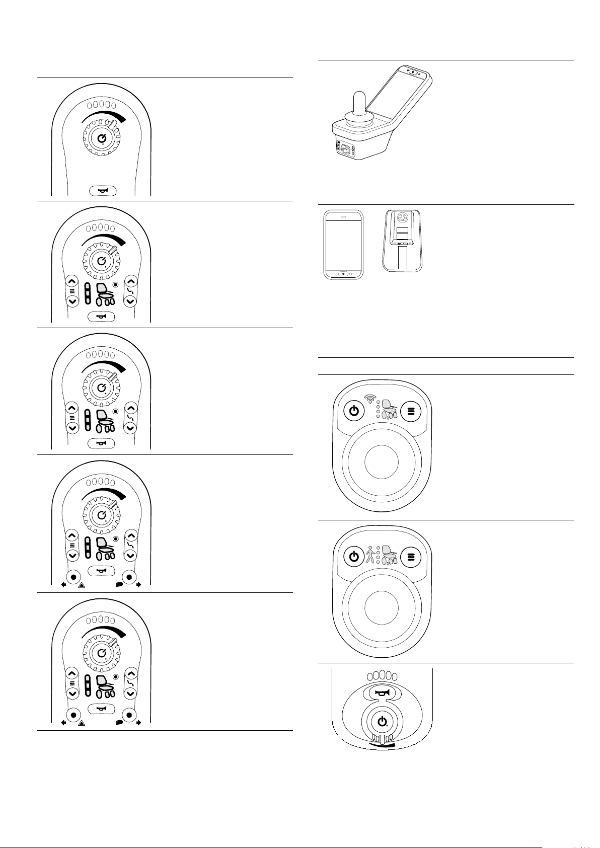
3.3Overviewcomponents
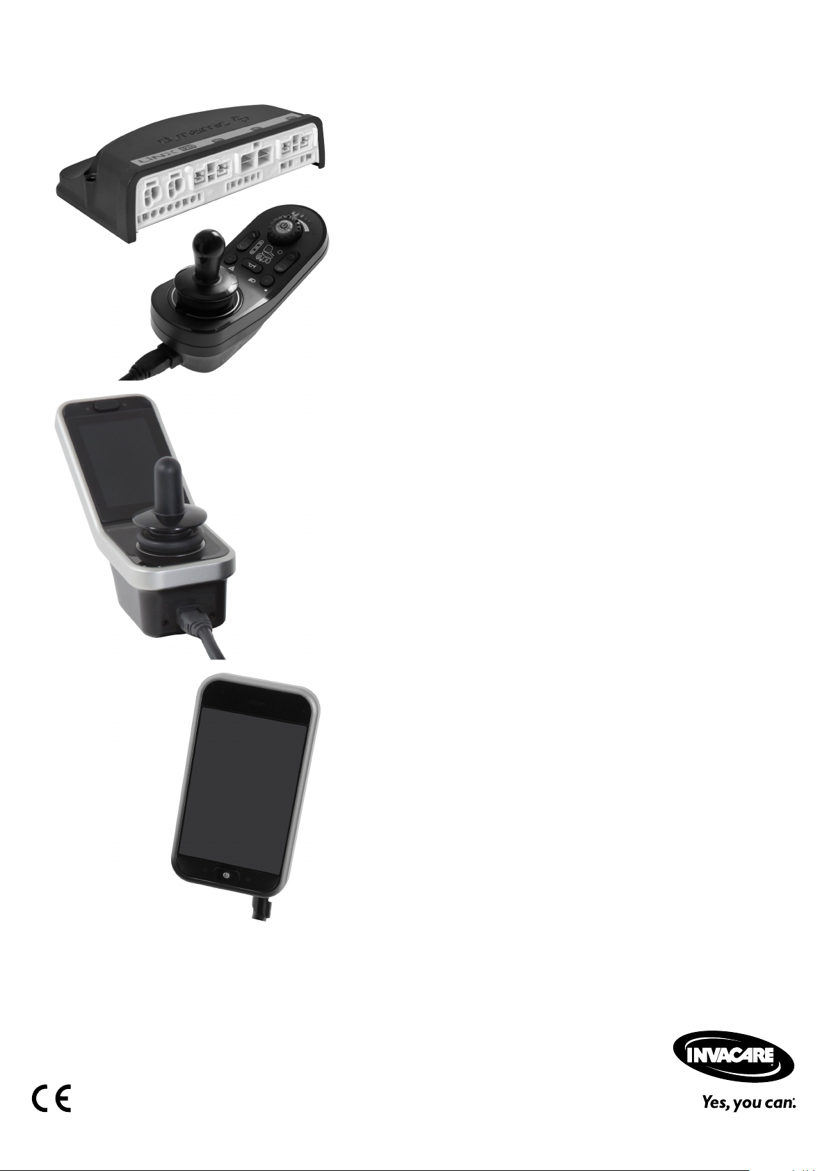
Remotemodules
DLX-REM110
•Drivefunction
DLX-REM210
•Drivefunction
•Poweredseating
function
Uptotwoactuators
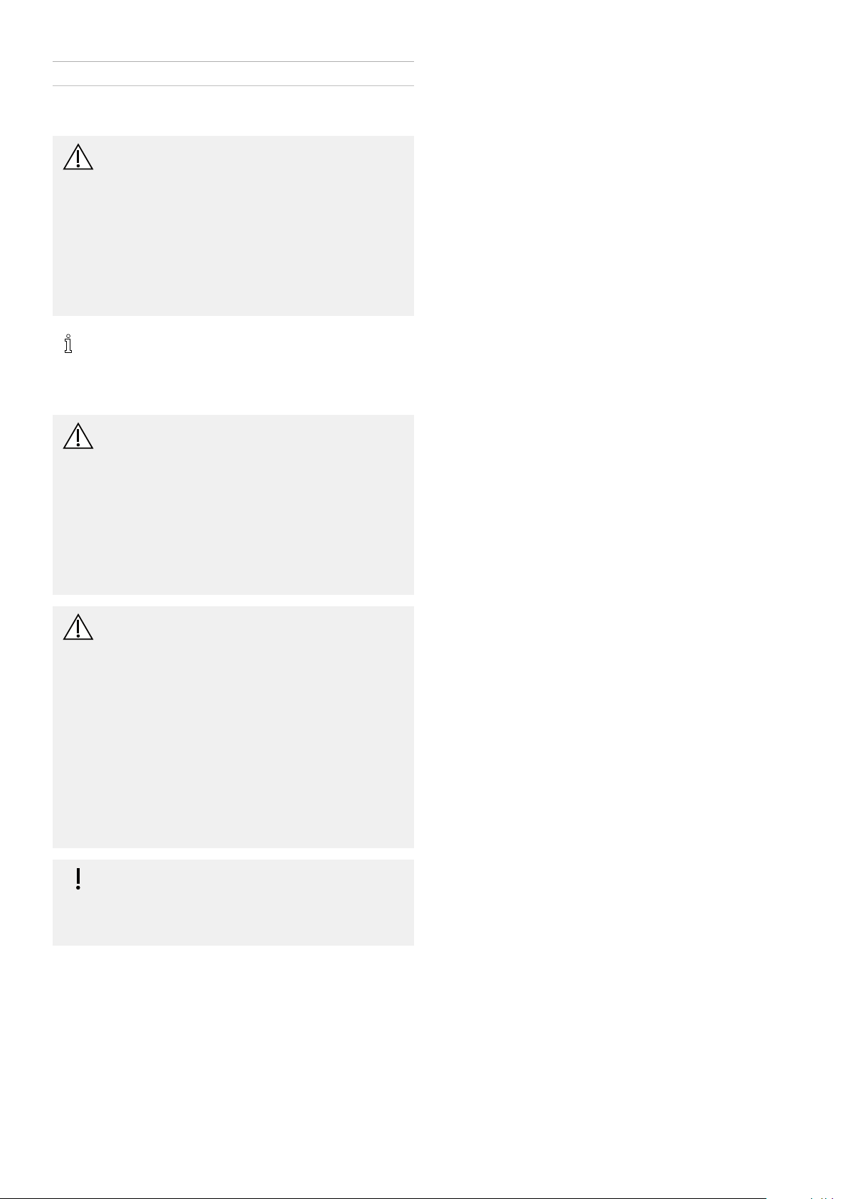
Remotemodules
DLX-REM400
•T ouchscreeninterface
tofacilitate:
–Multipledrive
functions
–Multiplepowered
seatingfunctions
Twoormore
actuators
–Lightingfunction
•Multipurposebuttons
•3.5mmjacksockets
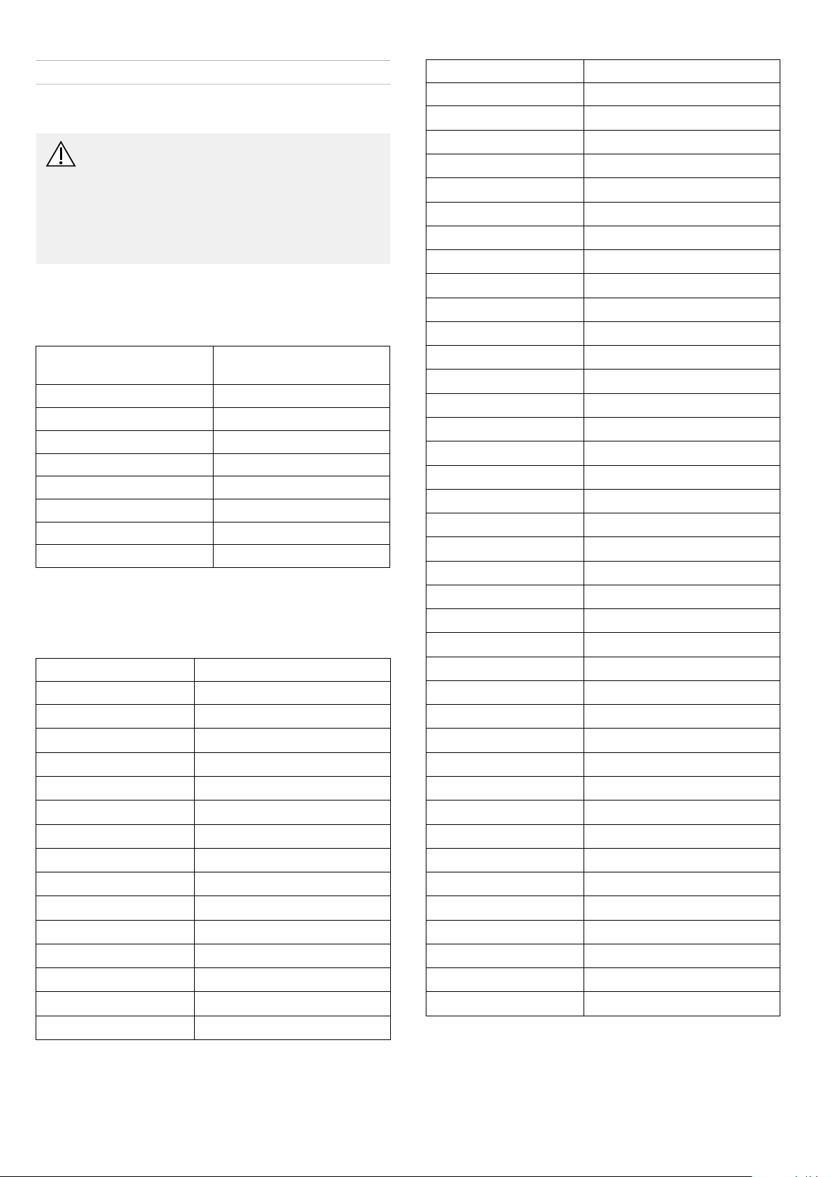
DLX-REM500
•T ouchscreeninterface
tofacilitate:
–Multipledrive
functions
–Multiplepowered
seatingfunctions
Twoormore
actuators
–Lightingfunction
•Multipurposebuttons
•3.5mmjacksockets
DLX-REM211
•Drivefunction
•Poweredseating
function
Twoormoreactuators
DLX-REM215
•Drivefunction
•Poweredseating
function
Uptotwoactuators
•Lightingfunction
DLX-REM216
•Drivefunction
•Poweredseating
function
Twoormoreactuators
•Lightingfunction
Secondaryremotemodules
DLX-CR400
CompactRemote
•On/Offbutton
•Menubutton
•Displayfordrive,
seatingand
connectivityfunctions
DLX-CR400LF
CompactRemoteLowForce
•Ascompactremote
•Withlowforcejoystick
DLX-ACU200
AttendantControlUnit
•On/Offrespectively
Selectbutton
•Menubutton
•Displayfordriveand
seatingfunctionsand
"who'sincharge"
indication
DLX-REM050
•Attendantcontrolunit
withdrivefunction
1605129-C
7
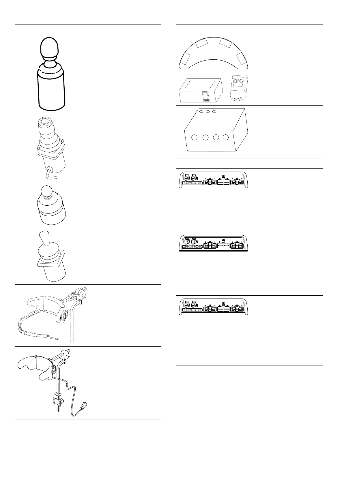
Invacare®LiNX
ASLcomponents
ASL138
ExtremityControlJoystick
ASL133
CompactSingleSwitch
Joystick
ASL130
MicroExtremityControl
Joystick
ASL132
CompactJoystick
ASL109
SipandPuffHeadArray
ASL104/ASL104P
HeadArray
ASLcomponents
ASL106
FourSwitchProximityArray
ASL504
RemoteStopSwitch
WirelessAccessoriesfor
ATOM:
•WirelessMouse
EmulatorASL558
•WirelessTripleSwitch
ReceiverASL557-3
Powermodules
DLX-PM60
•63Amaximumcurrent
•2xbussockets
•DynamicLoad
Compensation
•AdaptiveLoad
Compensation
•Utilityport
•Real-timeclock
DLX-PM75
•78Amaximumcurrent
•2xbussockets
•DynamicLoad
Compensation
•AdaptiveLoad
Compensation
•Utilityport
•Real-timeclock
DLX-PM120
•120Amaximum
current
•2xbussockets
•DynamicLoad
Compensation
•AdaptiveLoad
Compensation
•Utilityport
•Real-timeclock
81605129-C
Assembly
Powermodules
DLX-PM75AL
•78Amaximumcurrent
•2xbussockets
•DynamicLoad
Compensation
•AdaptiveLoad
Compensation
•Utilityport
•2xactuators
•3xlights
•Real-timeclock
DLX-PM120AL
•120Amaximum
current
•2xbussockets
•DynamicLoad
Compensation
•AdaptiveLoad
Compensation
•Utilityport
•2xactuators
•3xlights
•Real-timeclock
LiNXseatingmodulesandinterfaces
DLX-ACT200
•2xactuatorchannels
•2xbusports
•1x6–pingeneral
purposeinput(GPI)
port
•ModulestatusLED
•Actuatorpower
providedthroughthe
bus
DLX-ACT400
•4xactuatorchannels
•2xbusports
•1x6–pingeneral
purposeinput(GPI)
port
•ModulestatusLED
•Actuatorpower
providedthroughthe
bus
GLM-CONX4
4–wayconnector
•Expansionblockto
connecttoadditional,
multiplemodulesina
LiNXsystem
LiNXseatingmodulesandinterfaces
DLX-IN500
Inputmodule
•DB9connectorfor
proportionaland
switchedinputs
•12V(200mA)power
supply
•Sipandpuffnozzle
•Jackinput(stereo)
•2xLiNXbusconnector
•Activityindicator
displayinginput
demands
Buscable;lengthfrom300
upto2500mm
Extensionloom;length640
and900mm
Poweredseatingaccessories
ASL300
Eggswitch
•Momentaryswitch
•Normallyopen
•Monojack
Stereobuttonswitch
•2switches
•Stereojack
Stereotoggleswitch
•T oggleswitch
•Normallyopen
•Stereojack
4–waybuttonswitch
•4switches
•DB9connector
4–waytoggleswitch
•4toggledirections
•DB9connector
1605129-C9

Invacare®LiNX
Poweredseatingaccessories
10wayswitch
•Hardware-onlymodule
thatprovidessimple,
directaccessto
poweredseating
functions
DLX-FKEY01
•Forsystemswithone
physicalactuator
•Poweredseating
controlthroughegg
switch,stereobutton
switchorstereotoggle
switch
DLX-FKEY02
•Forsystemswithtwoor
morephysicalactuators
•Poweredseating
controlthrough4–way
buttonswitchor4–way
toggleswitch
Correctmounting
DLX-GYR100
LiNXG-Tracmodule
•stabilizeswheelchair’s
drivingbehavior
DLX-USB02
LiNXUSBcharger
•2USBchargerports
•1Achargingcurrent
perport
•Protectiverubber
bungs
3.4Powermodulemounting
Themountingorientationofthepowermodulethatis
speciedbyInvacareperwheelchairmodelmustbekept.
Dimensionsofthepowermodules
DLX-PM60,DLX-PM75,DLX-PM120
Rear
A
Connectors
B
Top
C
Base
D
Thepowermodulescanbeplacedonitssideoratanangle.
Whenplacingthepowermodulesatanangle,ensurethat
theconnectorsBfacingdownwards,sothattheconnector
recesseswillnotcollectorretainforeignmatterorliquids.
Incorrectmounting
DLX-PM75AL,DLX-PM120AL
101605129-C
Assembly
Rear
A
Connectors
B
Top
C
Base
D
Testing
TheLiNXsystemmustbefullytestedafterallmodulesand
cableshavebeeninstalled.
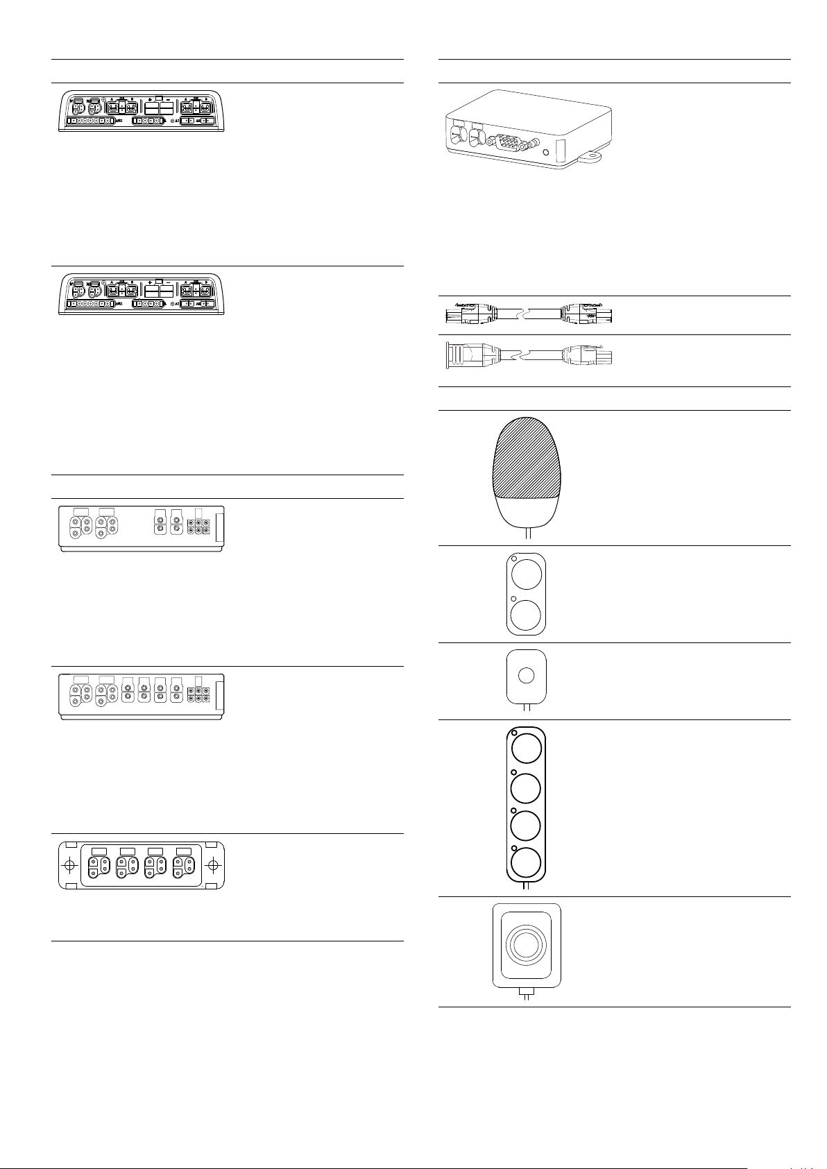
3.5Mountingpositionsonwheelchairs
ThepositionsofthepowermodulesAandDLX-ACT200/400Bdependingonwheelchairmodeland—congurationare
showninthetablebelow.Forfurtherinformationaboutaccesstothecomponents,refertotheServicemanualof
theparticularwheelchairmodel.
RearWheelDriveCenterWheelDrive
Fox
Kite,KiteHD
TDXSP2,TDXSP2narrow
base,TDXSP2widebasewith
Moduliteseat
TDXSP2narrowbaseand
TDXSP2widebasewithUltra
LowMaxxseat
Bora/SpectraXTR,Spectra
XTRHDw/olifter/tiltmodule
Bora/SpectraXTR,Spectra
XTRHDwlifter/tiltmodule
4
Storm
,Storm
4
Storm
1
4
X-plore,
1
Max
noDLX-ACT200/400onStorm
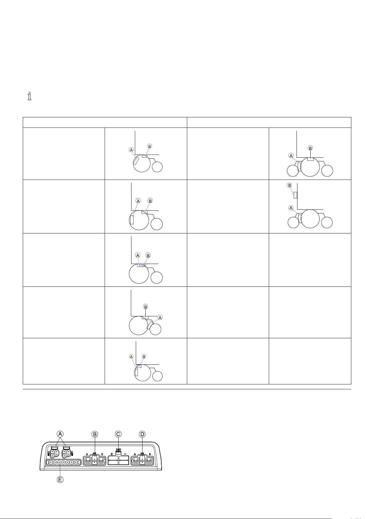
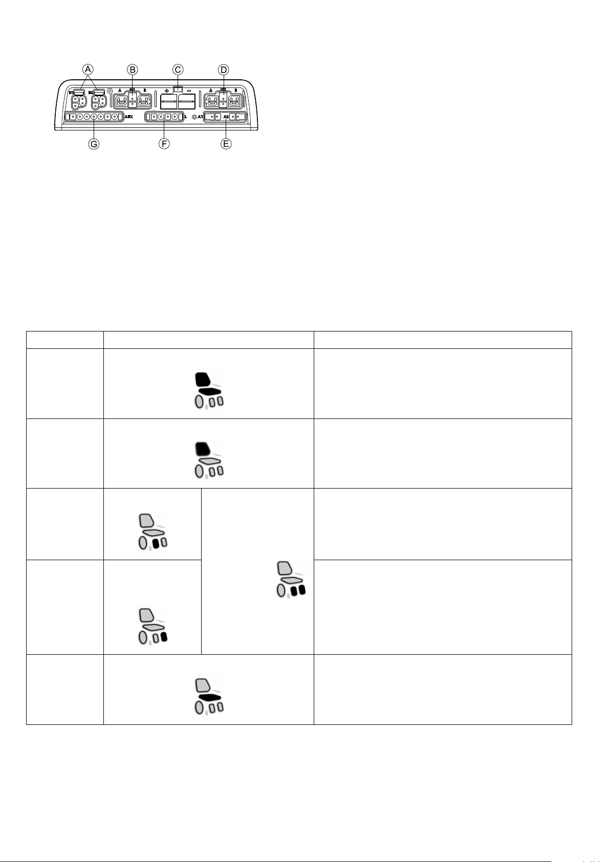
3.6Portpin-outs
DLX-PM60,DLX-PM75,DLX-PM120
4
Max
LiNXcommunicationbus
A
B
Motor/parkbrakeportM1
Batteryport
C
D
Motor/parkbrakeportM2
Utilityport
E
1605129-C
11
Invacare®LiNX
DLX-PM75AL,DLX-PM120AL
3.7Portcongurations(Factoryset-up)
Actuatorports,propertiesandbehaviorperactuatorare
denedbyInvacare.Youcanchangespeed,directionand
operationmode.Thisisdoneindifferentmenus,referto
7.5Modifyingseatingparameters,page62.
Seatingmotion
Theseatingmovementiscalledseatingmotion.Theseating
motiondenestheicondisplayedontheuserinterface,
LiNXcommunicationbus
A
B
Motor/parkbrakeportM1
Batteryport
C
D
Motor/parkbrakeportM2
Actuatorports
E
Lightingport
F
Utilityport
G
overallspeed,theindividualactuatorsandtheirspeeds.A
seatingmotioncancontroloneormoreactuators.Thereare
sixseatingmotionsdenedinthefactoryset-up.
Seatingfunction
Theseatingfunctionistheuserinputanddeneshowthe
motionisoperated.
The“AL”powermodulesthatfeatureactuatorsand
lights,havetwoactuatorports.Ifrequired,thesystemis
completedwiththeDLX-ACT200orDLX-ACT400,basedon
theconguration.Thefollowingchaptersdetailtheport
set-uppermodule/conguration.
3.7.1PortcongurationsforsystemswithDLX-REM2xx(EU-VersionwithModuliteseat)
Channel
A
Seatingmotion(Icon)Seatingfunction(Operation)
Tilt
ProportionalFWD/REV
B
C
Recline
Rightleg
ProportionalFWD/REV
ProportionalFWD/REV
Bothlegs
D
Leftleg/
ProportionalFWD/REV
Center-mounted
legrest
E
Lifter
ProportionalFWD/REV
12
1605129-C
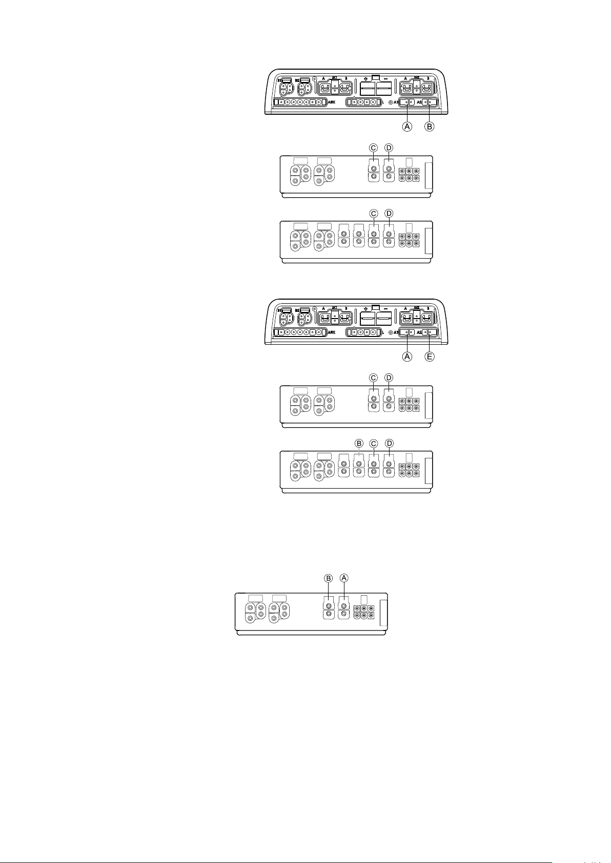
Portcongurationwithoutlifter
Powermodule
DLX-ACT200
DLX-ACT400
Portcongurationwithlifer
Powermodule
Assembly
DLX-ACT200
DLX-ACT400
3.7.2Portcongurationfornon-expandablesystems(USversion)
Non-expandablesystemsarettedwithexternalswitchesandafunctionkey ,tocontrolthepoweredseatingfunctions.For
moreinformationaboutfunctionkeys,refertochapter3.7.4Portcongurationsforfunctionkeys,page15.
Singleactuatorsystems
1605129-C13
Invacare®LiNX
Channel
A
B
B
Twoactuatorsystems
Channel
A
Seatingmotion(Icon)Seatingfunction(Operation)
Reclineonly
Tiltonly
LNXonly
Seatingmotion
(Icon)
Seatingmotion
(Icon)
Seatingmotion
(Icon)
Seatingmotion
(Icon)
ProportionalFWD/REV
ProportionalFWD/REV
ProportionalFWD/REV
Seatingmotion
(Icon)
Seating
function
(Operation)
Tilt
TiltReclineLeftlegReclineProportional
FWD/REV
B
Lifter
LNXLNX
RightlegTiltProportional
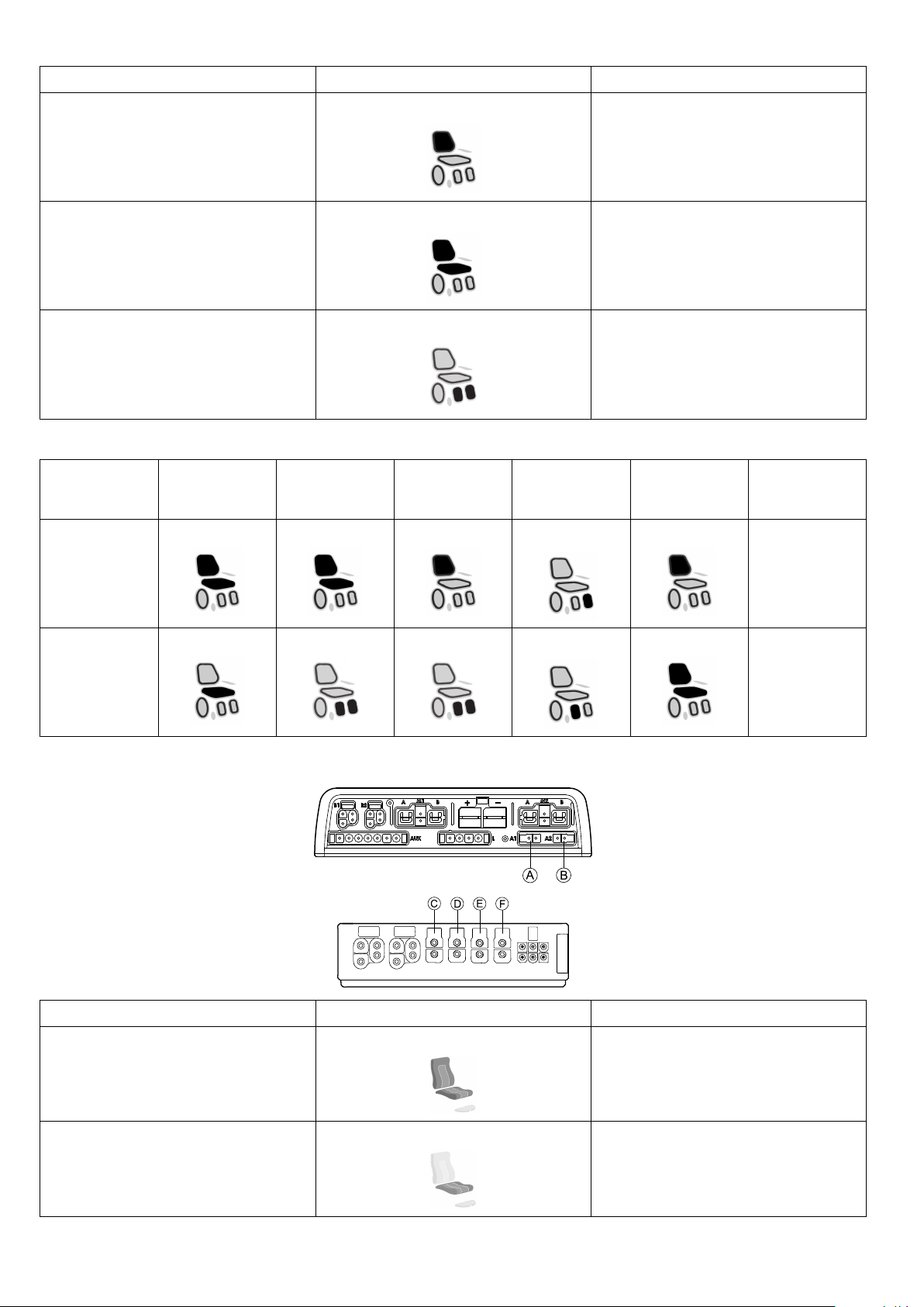
3.7.3PortcongurationforsystemswithDLX-REM400andDLX-REM500(withUltraLowMaxxseat)
Channel
A
Seatingmotion(Icon)Seatingfunction(Operation)
Tilt
ProportionalFWD/REV
FWD/REV
B
14
Lifter
ProportionalFWD/REV
1605129-C
Assembly
Channel
C
D
E
F
3.7.4Portcongurationsforfunctionkeys
Seatingmotion(Icon)Seatingfunction(Operation)
Legrestright
Legrestleft
LNX
Recline
ProportionalFWD/REV
ProportionalFWD/REV
ProportionalFWD/REV
ProportionalFWD/REV
Ifthesystemisttedwithanexternalswitch,tocontrolthepoweredseatingfunctions(excepta10wayswitch),afunctionkey
isrequiredtointerfacetheswitches.Therearefourdifferentcongurationsoffunctionkeys.Thetypeoffunctionkeydetermines
thebehaviorofthesysteminregardstothecontrolofactuators.
Type1:SingleActuatorSystem(SAS)
Thisfunctionkeyisforsystemswithonephysicalactuator.Itisavailableintwodifferentcongurations:
•FKEY01:actuatorcontrolthroughswitchesonly
•FKEY01TDC:actuatorcontrolthroughswitchesandjoystick
IndependentoftypeFKEY01orFKEY01TDCtheexternalswitchestocontrolthepoweredseatingfunctions,mustbeplugged
intotheJacksockets,seetablebelow.
A
B
Monojacktoconnecteggswitch
Stereojacktoconnectstereobuttonswitchorstereotoggleswitch
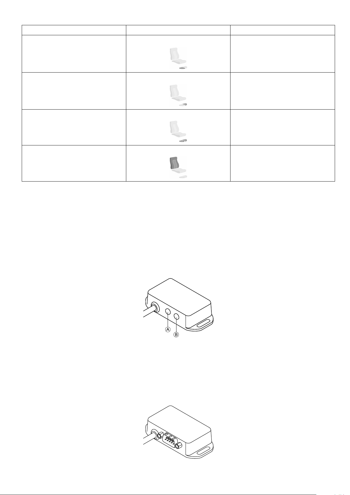
Type2:Multi-ActuatorSystem(MAC)
Thisfunctionkeyisforsystemswithtwoormorephysicalactuators.Itisavailableintwodifferentcongurations:
•FKEY02:actuatorcontrolthroughswitchesonly
•FKEY02TDC:actuatorcontrolthroughswitchesandjoystick
1605129-C15
Invacare®LiNX
IndependentoftypeFKEY02orFKEY02TDCthe4–waybuttonswitchorthe4–waytoggleswitchmustbepluggedintothe
DB9socket.
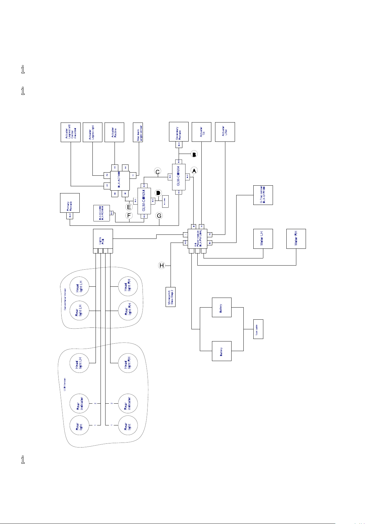
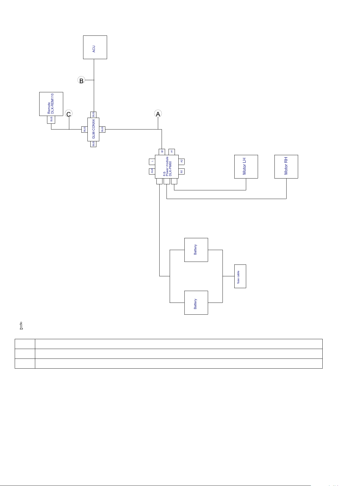
3.8Wiringdiagrams
Thefollowingdiagramsshowthewiringforawheelchairinacomplexcongurationincludingmultipleactuators,
lightsandattendantcontrolunit.
Toidentifytherequiredcablelength,seetablesbelowormeasurethecableafterremovingit.
WiringforcongurationsofModuliteseatwithlifter,tilt,recline,poweredelevatinglegrests,lights,attendantcontrolunit,
secondaryremote,DLX-ACT400andUSBcharger
Cablelengthmayvarydependingonmountingpositionsofprimaryandsecondaryremotesandof4–wayconnector
GLM-CONX4.
161605129-C
Assembly
Model
Kite
Spectra
XTR
A
A A
•2500
mm
•1700
2
HD,
mm
B
B B
•1500
mm
•1700
mm
C
C C
•300
mm
•300
mm
D
D D
•700
mm
•700
mm
E
E E
•700
mm
•700
mm
F
F F
•1500
mm
•1200
mm
G
G G
•1700
H
H H
•700
mm
•1500
•700
mm
Bora/SpectraXTR
Standard
TDXSP2•1500
4
Storm
,
4
Storm
mm
•1500
mm
•1200
mm
•1200
mm
•300
mm
•300
mm
•300
mm
•500
mm
•700
mm
•300
mm
•1000
mm
•1200
mm
•1200
•300
mm
•1500
•300
mm
X-plore
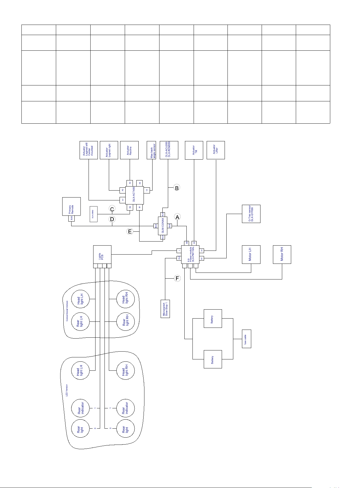
WiringforcongurationsofModuliteseatwithlifter,tilt,recline,poweredelevatinglegrests,lights,attendantcontrol
unit,DLX-ACT400andUSBcharger
mm
mm
mm
mm
1605129-C
17
Invacare®LiNX
Cablelengthmayvarydependingonmountingpositionsofprimaryandsecondaryremotesandof4–wayconnector
GLM-CONX4.
Model
Kite
Spectra
XTR
A
A A
B
B B
•2500mm•1500mm•700mm•1700mm•700mm•700mm
•1700mm•1200mm•700mm•1500mm•700mm•700mm
2
HD,
C
C C
D
D D
E
E E
F
F F
Bora/Spectra
XTRStandard
TDXSP2•1500mm•1000mm•300mm•1500mm•700mm•300mm
4
Storm
,Storm
4
•1500mm•1200mm•500mm•1500mm•300mm•300mm
X-plore
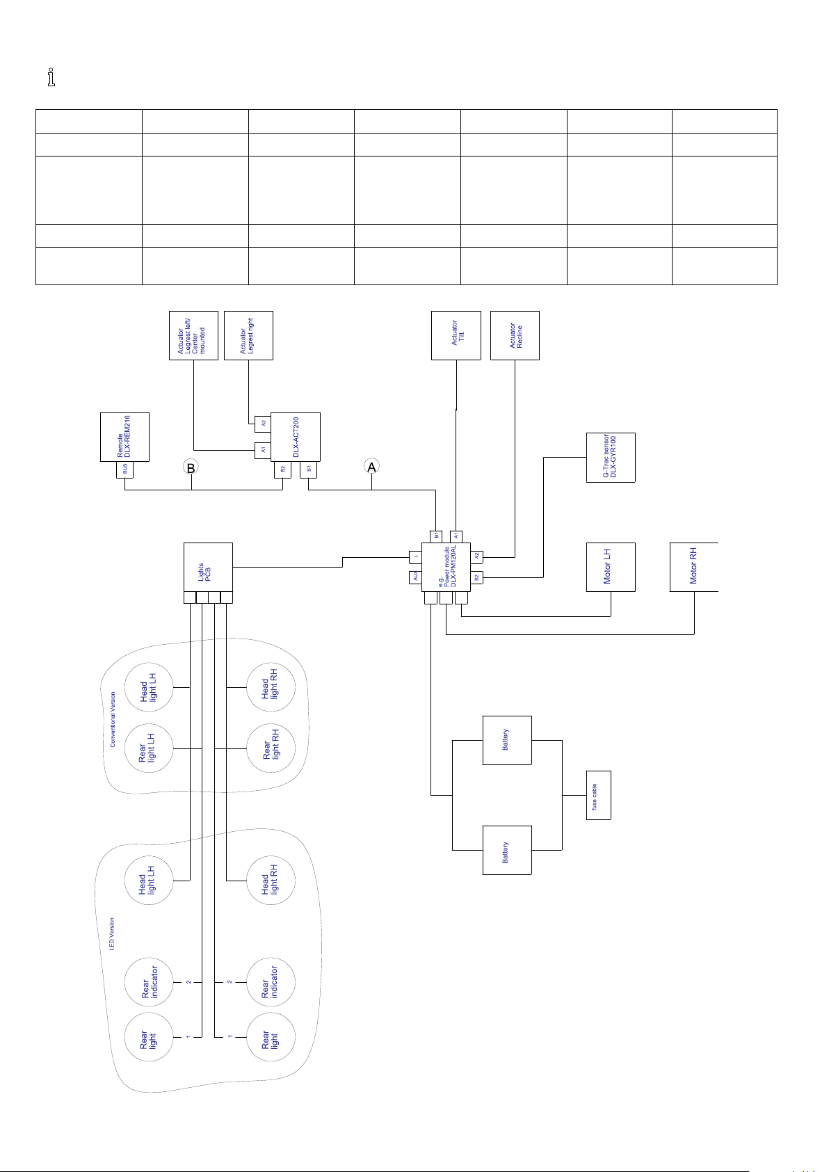
WiringforcongurationsofModuliteseatwithtilt,recline,poweredelevatinglegrests,lightsandDLX-ACT200
181605129-C
Cablelengthmayvarydependingonmountingpositionsofprimaryandsecondaryremotes.
Assembly
Model
Kite
SpectraXTR
2
HD,Bora/SpectraXTR
A
A A
B
B B
•1500mm•1500mm
•1500mm•1500mm
Standard
TDXSP2•1700mm•1000mm
4
Storm
,Storm
4
X-plore
•1200mm•1500mm
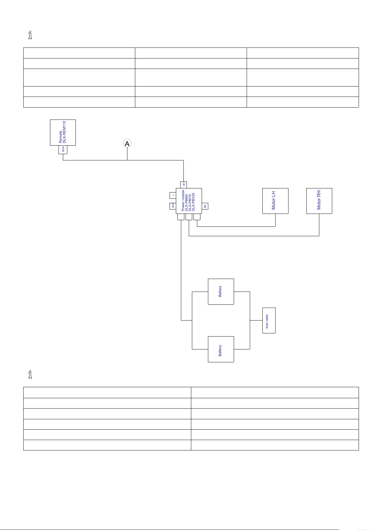
WiringforDriveonlycongurationofModuliteseat
Cablelengthmayvarydependingonmountingpositionsofprimaryremote.
Model
Kite
SpectraXTR
2
HD,Bora/SpectraXTRStandard
A
A A
•2000mm
•2000mm
TDXSP2•1500mm
4
Storm
,Storm
Fox
1605129-C19
4
X-plore
•2000mm
•300mm+640mmextensionloom
Invacare®LiNX
WiringforFoxwithModuliteDriveonlywithACU
Cablelengthmayvarydependingonmountingpositionsofprimaryandsecondaryremotesandof4–wayconnector
GLM-CONX4.
A
B
C
201605129-C
•1000mm
•1200mm
•1000mm
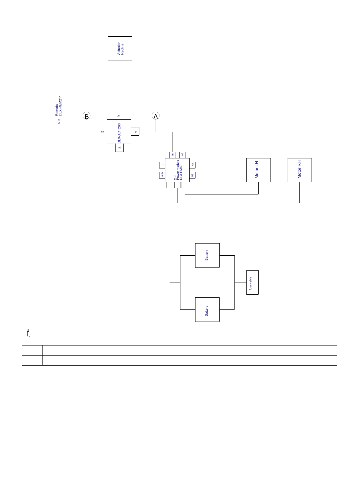
WiringforFoxwithModuliteReclineonly
Assembly
Cablelengthmayvarydependingonmountingpositionsofprimaryremote.
A
B
1605129-C
•1000mm
•1000mm
21
Invacare®LiNX
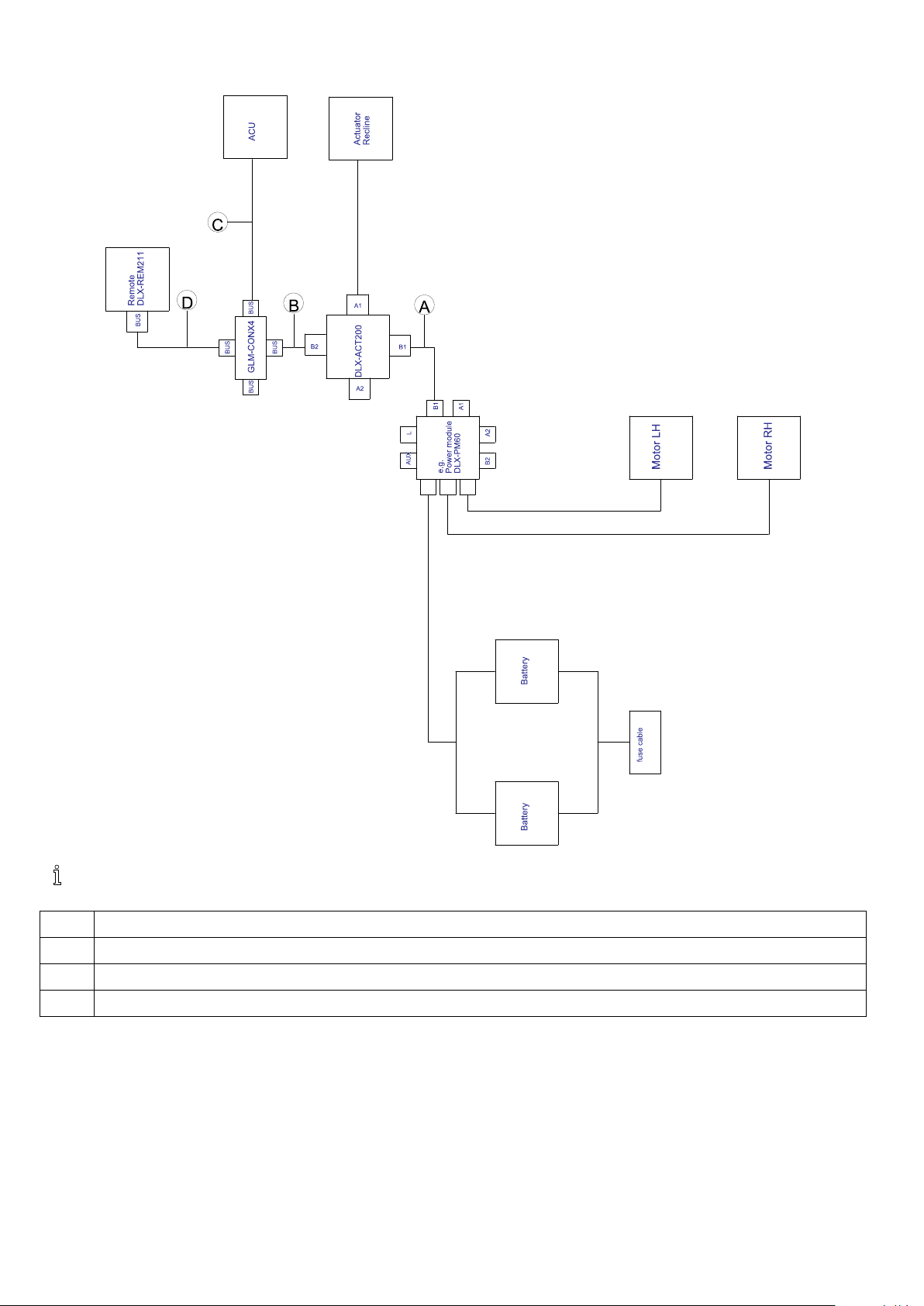
WiringforFoxwithModuliteReclineonlyandACU
Cablelengthmayvarydependingonmountingpositionsofprimaryandsecondaryremotesandof4–wayconnector
GLM-CONX4.
A
B
C
D
22
•1000mm
•300mm
•1200mm
•1000mm
1605129-C
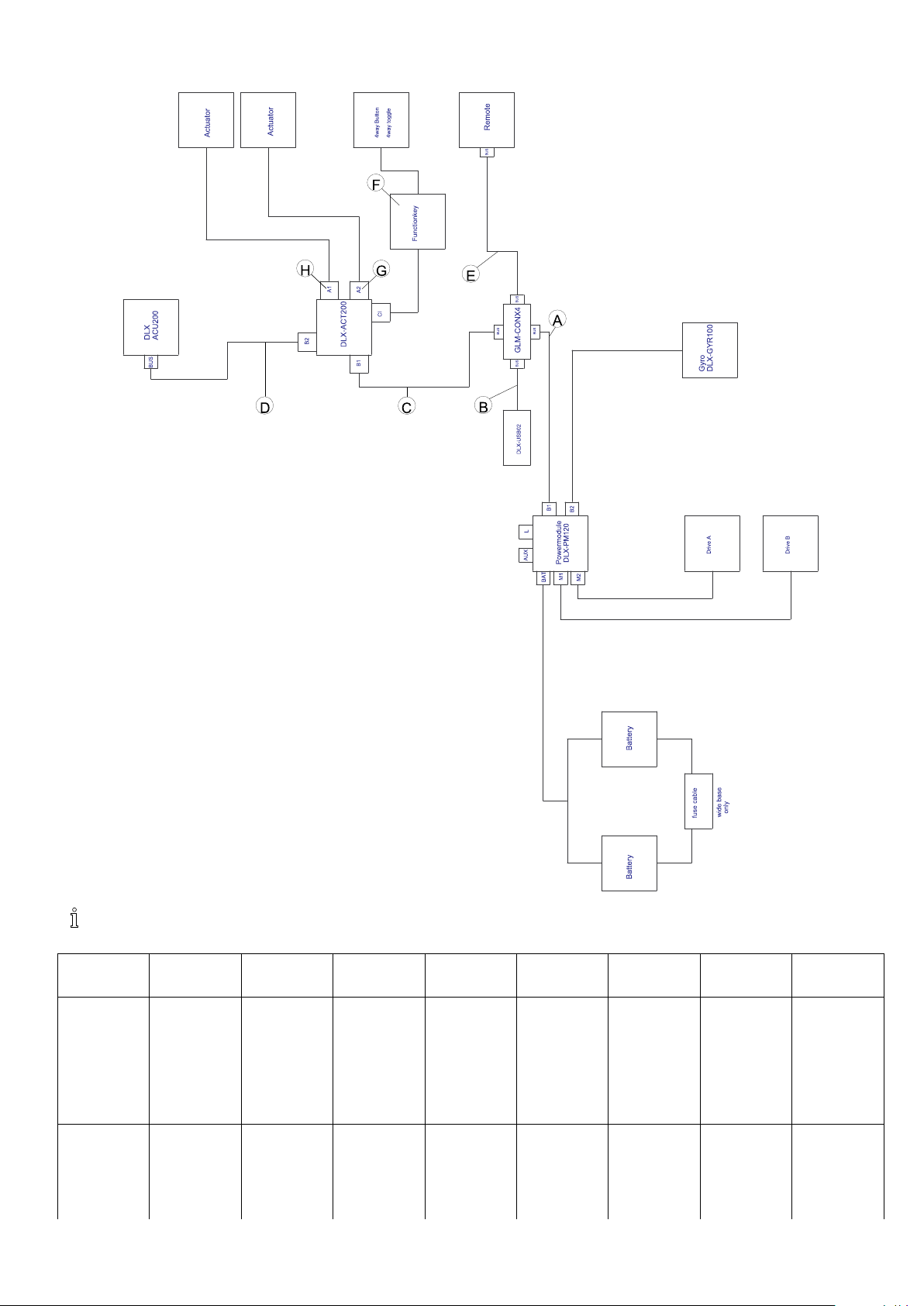
WiringforNonexpandablesystemswithUltraLowMaxxseat(USonly)
Assembly
Cablelengthmayvarydependingonmountingpositionsofprimaryandsecondaryremotesandof4–wayconnector
GLM-CONX4.
Congura-
A
A A
B
B B
C
C C
D
D D
E
E E
F
F F
G
G G
H
H H
tion
Reclineonly
•1200
mm
•300
mm
•700
mm
•300
mm
•1500
mm
•Functionkey
•not
used
•Recline
connected
FKEY01/FKEY01
TDC
Tilt/Recline
•1200
mm
•300
mm
•700
mm
•300
mm
•1500
mm
•Functionkey
•Tilt
connected
•Recline
connected
FKEY02/F-
1605129-C23

Invacare®LiNX
Conguration
LNXonly
Tiltonly
Duallegs
Recline/LNX
Tilt/LNX
Tilt/Lifter
A
A A
B
B B
C
C C
D
D D
E
E E
F
F F
G
G G
H
H H
KEY02
TDC
•1200
mm
•300
mm
•1200
mm
•300
mm
•1500
mm
•Functionkey
•LNX
connected
•not
used
FKEY01/FKEY01
TDC
•1200
mm
•300
mm
•1200
mm
•300
mm
•1500
mm
•Functionkey
•Tilt
connected
•not
used
FKEY01/FKEY01
TDC
•1200
mm
•300
mm
•1200
mm
•300
mm
•1500
mm
•Functionkey
FKEY-
•Legrest
right
connected
•Legrest
left
connected
02/FKEY02
TDC
•1200
mm
•300
mm
•1200
mm
•300
mm
•1500
mm
•Functionkey
•LNX
connected
•Recline
connected
FKEY02/FKEY02
TDC
•1200
mm
•300
mm
•1200
mm
•300
mm
•1500
mm
•Functionkey
•LNX
connected
•Tilt
connected
FKEY02/FKEY02
TDC
•1200
mm
•300
mm
•1200
mm
•300
mm
•1500
mm
•Functionkey
•Lifter
•Tilt
connected
con-
nected
FKEY02/FKEY02
TDC
24
1605129-C

WiringforcongurationswithUltraLowMaxxseat
Assembly
Cablelengthmayvarydependingonmountingpositionsofprimaryandsecondaryremotesandof4–wayconnector
GLM-CONX4.
Dependingonconguration,theEggswitchASL300canbeconnectedtotheprimaryremote.
1605129-C25
Invacare®LiNX
Conguration
A
B
C
D
1
E
F
G
H
I
J
K
1
BusporteitherforDLX-CR400orforRemoteStopSwitch.Cannotbecombined.
wtilt,wrecline,w/o
lifter
wtilt,w/orecline,
w/olifter
•1200mm•1200mm•1500mm•1500mm
•1500mm•1700mm•1700mm•1700mm
•700mm•1200mm•700mm•1200mm
•300mm•300mm•300mm•300mm
•1700mm•1200mm•1200mm•1200mm
•300mm•300mm•300mm•300mm
•300mm•300mm•300mm•300mm
•300mm•300mm•300mm•300mm
•300mm•300mm•300mm•300mm
•300mm•300mm•300mm•300mm
•300mm•300mm•300mm•300mm
3.9Mountingtheprimaryremotes
Formoreinformationabouthowremoteholders
aremountedtothewheelchair ,refertotheservice
manualoftheseatingsystem.
wtilt,wrecline,w
lifter
Swingawayremoteholder
•4mmAllenkey
•3mmAllenkey
•8mmwrench
•10mmwrench
wtilt,w/orecline,w
lifter
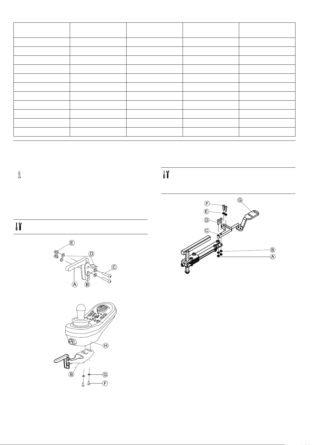
3.9.1MountingDLX-REM1XXandDLX-REM2XXfor Modulite
Standardremoteholder
•3mmAllenkey
•8mmwrench
1.
MountjoystickholderAtoremoteadapterBwith
screwsC,washersDandnutsE.
2.
1.PullscrewsDthroughbracketC,remoteholderand
washersB.
2.TightenscrewswithnutsA.
MountremoteHtoremoteadapterBwithscrewsF
andwashersG.
261605129-C

Assembly
3.PullscrewsFthroughwashersE,bracketCand
bracketGandtightenscrews.
4.
TightenremoteHwithscrewsJandwashersTto
bracketG.
Remoteholderforattendant
Theremoteisttedtothewheelchairusingabracketonthe
pushhandleorthepushbar.
•4mmAllenkey
•3mmAllenkey
1.PullscrewsAthroughwashersB,mountingplateC
andbottomsideofbracketD.
2.Tightenbottomsideofthebrackettopushbarwiththe
topsideofthebracketEandnutsF.
3.
FixremotetobracketIwithscrewsGandwashersH.
Formountingpositions,referto3.10.3Mountingthe
DLX-REM050,page33.
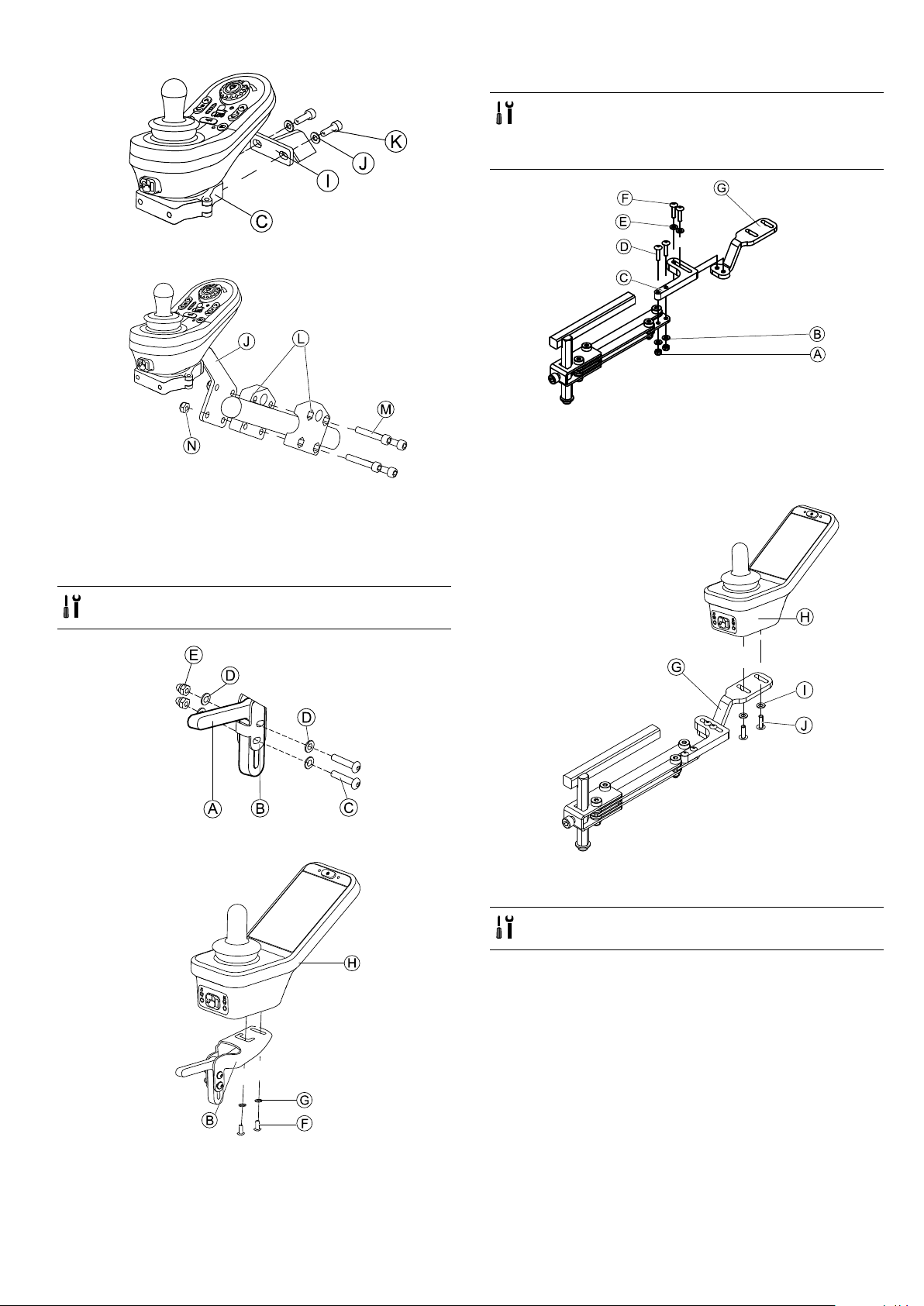
3.9.2MountingDLX-REM2XXforUltraLowMaxx
Standardremoteholder
•3mmAllenkey
•8mmwrench
1.
MountjoystickholderAtoremoteadapterBwith
screwsC,washersDandnutsE.
2.
MountremoteHtoremoteadapterBwithscrewsF
andwashersG.
Swingawayremoteholder
•3mmAllenkey
•4mmAllenkey
•8mmwrench
•10mmwrench
1605129-C
27

Invacare®LiNX
1.PullscrewsDthroughbracketC,remoteholderand
washersB.
2.TightenscrewswithnutsA.
3.PullscrewsFthroughwashersE,bracketCand
bracketGandtightenscrews.
4.
1.MountLiNXremoteadapterBwithscrewsAtoremote
C.
TheLiNXremoteadaptercanbeturned90°right
orleftformoreadjustmentoptions.
2.MountremotetoQuadLinkFwithscrewD,Nord-Lock
washerEandserratedlockwasherG.
TightenscrewDwithamaximumtorqueof25
Nm.
Remoteholderforattendant
Theremoteisttedtothewheelchairusingabracketonthe
pushhandleorthepushbar.
•3mmAllenkey
•5mmAllenkey
•8mmwrench
1.
TightenremoteHwithscrewsJandwashersTto
bracketG.
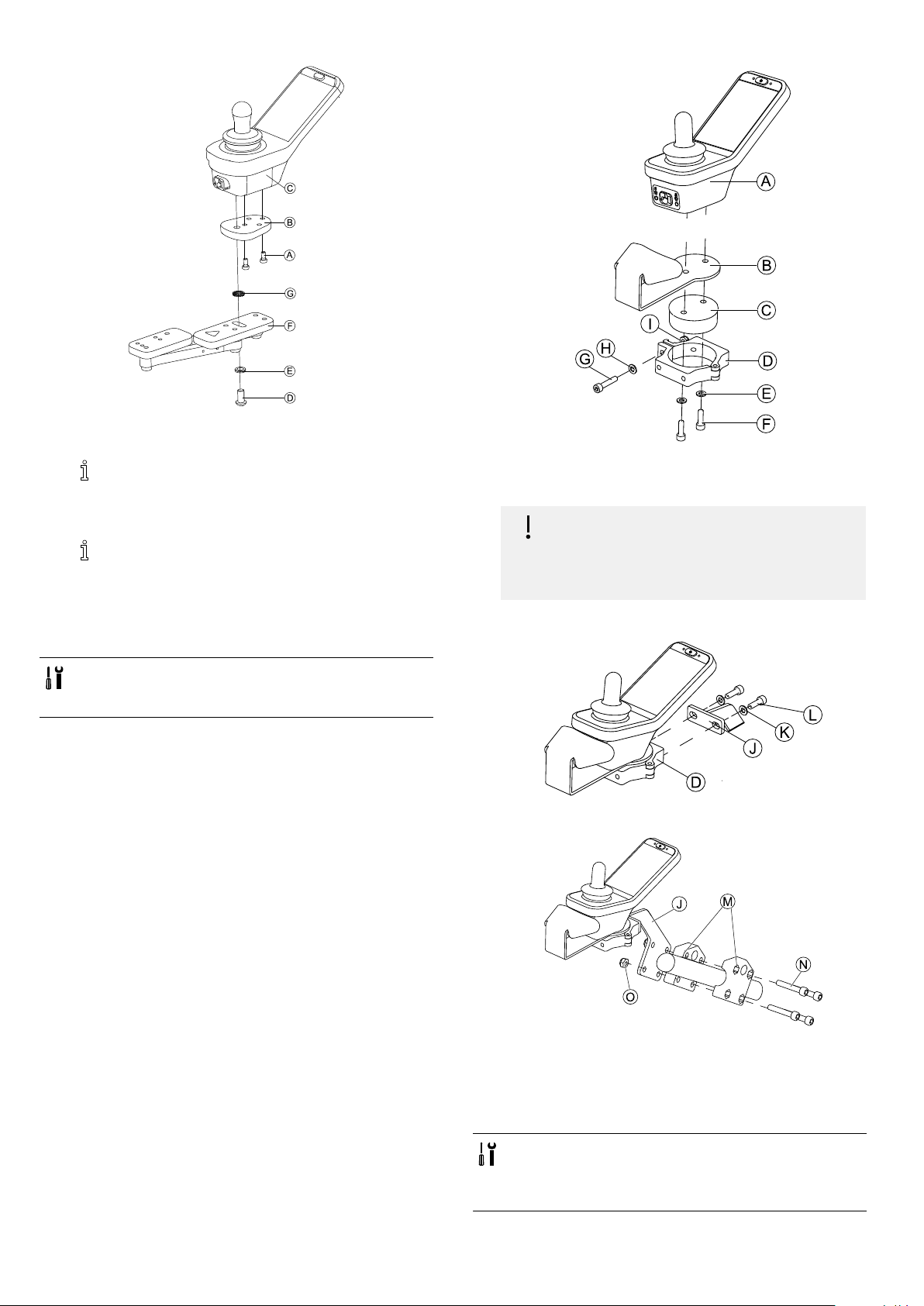
QuadLinkremoteholder
•3mmAllenkey
•5mmAllenkey
MountremoteAwithandsupportdrumBtoclampC
withscrewsEandwashersD.
2.
Riskofdamagetotheremote
Themaximumtorquetotightenthescrew
is1Nm.
–Donotexceedthisratingasitmaydamage
theremote.
FixsupportdrumBinclampCwithscrewF,washer
GandnutH.
281605129-C
Assembly
3.
AttachclampCtobracketIwithscrewsKand
washersJ.
4.
AttachbracketItogripperclampLwithscrewsM
andnutsN.
Swingawayremoteholder
•4mmAllenkey
•3mmAllenkey
•8mmwrench
•10mmwrench
1.PullscrewsDthroughbracketC,remoteholderand
washersB.
2.TightenscrewswithnutsA.
3.PullscrewsFthroughwashersE,bracketCand
bracketGandtightenscrews.
4.
3.9.3MountingtheDLX-REM400
Standardremoteholder
•3mmAllenkey
•8mmwrench
1.
MountjoystickholderAtoremoteadapterBwith
screwsC,washersDandnutsE.
2.
TightenremotewithscrewsAtobracketG.
QuadLinkremoteholder
•3mmAllenkey
•5mmAllenkey
MountremoteHtoremoteadapterBwithscrewsF
andwashersG.
1605129-C29
Invacare®LiNX
1.MountLiNXremoteadapterBwithscrewsAtoremote
C.
TheLiNXremoteadaptercanbeturned90°right
orleftformoreadjustmentoptions.
2.MountremotetoQuadLinkFwithscrewD,Nord-Lock
washerEandserratedlockwasherG.
TightenscrewDwithamaximumtorqueof25
Nm.
Remoteholderforattendant
Theremoteisttedtothewheelchairusingabracketonthe
pushhandleorthepushbar.
•3mmAllenkey
•5mmAllenkey
•8mmwrench
1.
MountremoteAwithsupportBandsupportdrumC
toclampDwithscrewsFandwashersE.
2.
Riskofdamagetotheremote
Themaximumtorquetotightenthescrew
is1Nm.
–Donotexceedthisratingasitmaydamage
theremote.
FixsupportdrumCinclampDwithscrewG,washer
HandnutI.
3.
AttachclampDtobracketJwithscrewsLand
washersK.
4.
AttachbracketJtogripperclampMwithscrewsN
andnutsO.
3.9.4MountingtheDLX-REM500
Swingawayremoteholder
•3mmAllenkey
•4mmAllenkey
•Medium-strengththread-lockinguid,e.g.
Loctite243
301605129-C
 Loading...