

Invacare Hydra C650PW Owner's Manual

1
Invacare Australia Pty Ltd
ACN 074676378
1 Lenton Place
(PO Box 5002)
North Rocks NSW 2151
Ph: +61 2 8839 5333
Fax: +61 2 8839 5353
sales@invacare.com.au
August 2004
Hydra
C650PW Folding Power Wheelchair
2
WARNING !
DO NOT OPERATE THIS ELECTRIC WHEELCHAIR WITHOUT
FIRST READING AND UNDERSTANDING THIS MANUAL. IF YOU
ARE UNABLE TO UNDERSTAND THE WARNINGS AND
INSTRUCTIONS, CONTACT THE DISTRIBUTOR OR DEALER
WHERE YOUR ELECTRIC WHEELCHAIR PURCHASED BEFORE
ATTENPTING TO USE THIS EQUIPMENT OTHERWISE INJURY
OR DAMANGE MAY RESULT.
Chair User Classification
Model Max user
Weight
Everyday
Use
Indoor
Use
Outdoor
Use
C650PW Folding power wheel chair
100 KGS
X
X
X
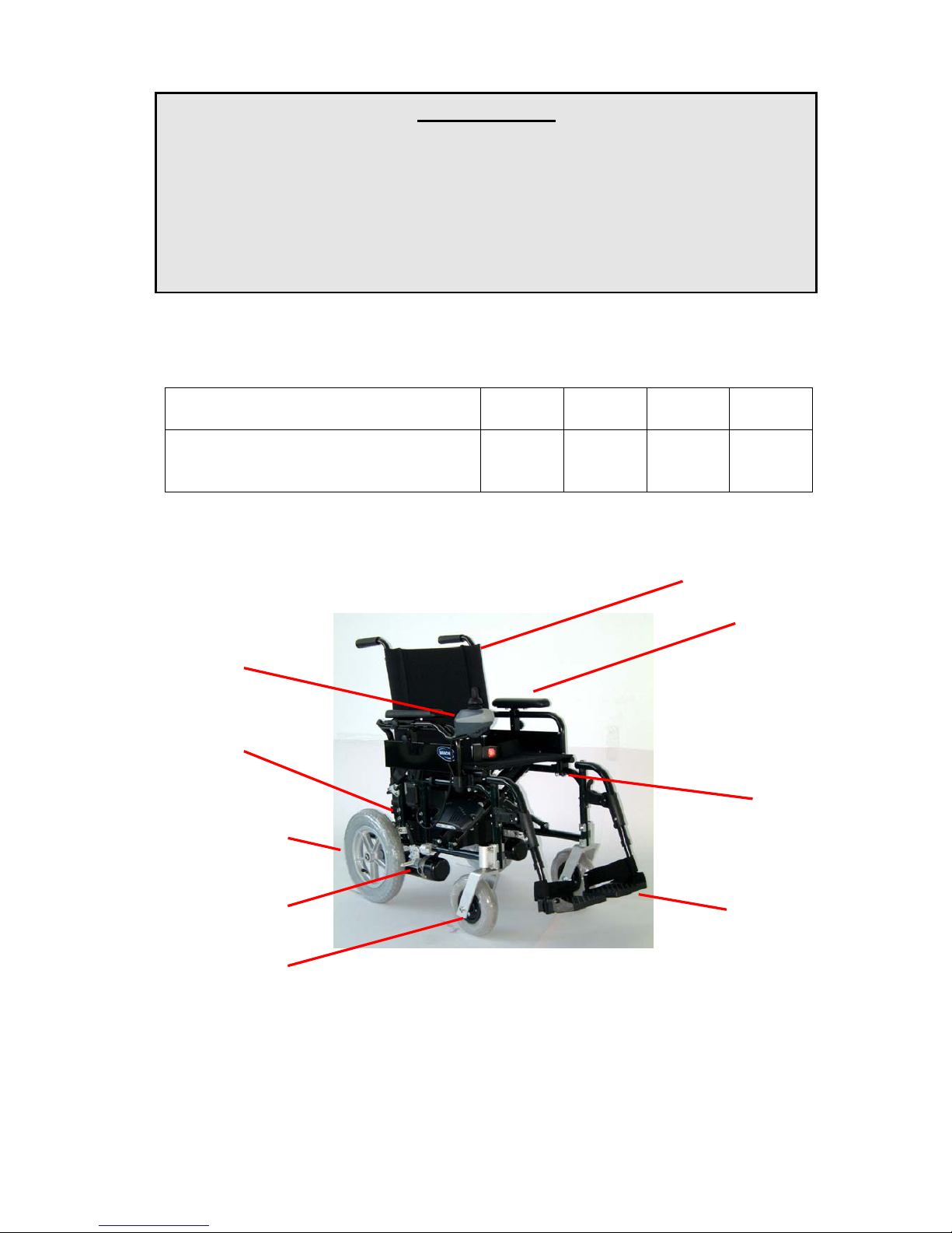
Back upholstery
Armrest
Controller
Batteries
Frame
Rear wheel set
Legrests
Casters & fork
Motor / gear box

3
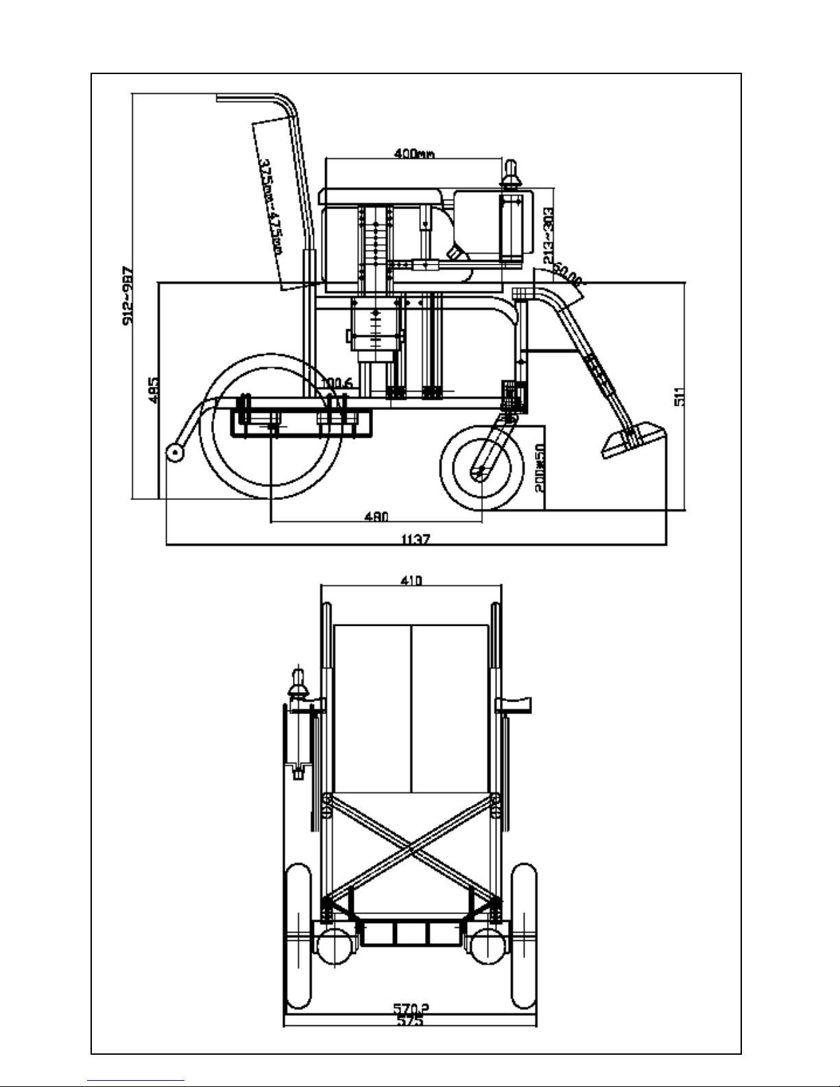
SPECIFICATION
No
Item Specification
1 Seat Width 406 mm (16 in) / 457 mm (18 in)
2 Seat Depth 406 mm (16 in) / 457 mm(18 in)
3 Seat Height front 513 mm (20 in) / rear 490 mm (19 in)
4 Back Rest
Back height (from seat to the top of
back upholstery)
8° bend
375 mm (14.5 in) ~ 475 mm (18.5 in ) height adjustable
5 Rear drive Wheels Dia. 325 mm(12.5 in) pneumatic tyre
6 Front Wheels Dia. 200mm (8 in) pneumatic tyre
7 Anti-tip Wheels Dia. 40 mm (1.5 in) wheels
8 Brake & wheel locks Electro-magnetic brake, and
BR-A550 alloy wheel lock
9 Manual Freewheel Yes, Easily accessible without disassembly
10 Adjustable Back Rest 8 degree bend, height adjustable
11 Adjustable Armrest Height adjustable from 213 mm (8.5 in) ~ 378 mm (15 in)
12 Battery MK-MU-1 Gel Battery 12 volt / 31 amp, 2 pcs
13 Battery Charger Off board. BAT - GC0822. 8 Amp.
14 Controller Shark Dynamic Controller
15 Drive Train 250W.Rear wheel drive with two motors,
permanent magnet commutator 24V DC motors.
16 Weight Capacity 100kg (220 lbs)
17 Max Speed 6.5 km/h (4 MPH)
18 Ground clearance to Batteries 135 mm (5.3 in)
19 Ground clearance to Anti-tip
Wheels
35 mm (1.4 in)
20 Turning Radius 965 mm (38 in)
21 Climbing Angle 10°
22 Range 24 km (15 miles)
(Varies with passenger weight, temperature, condition of batteries, ground surface, type
of charger & battery etc. )
23 Overall Length 1150 mm (45 in)
24 Overall Width
570 mm (16 in) seat width / 620 mm (18 in)
seat width
25 Overall Height Height adjustable from 911 mm (36 in) ~ 986 mm (39 in)
(from underground to push handle)
26 Weight - base incl. controller,
motors, legrests w/o anti-tipper,
seat cushion, batteries.
33 kg (72.6 lbs)
27 Battery weight 11 kg (24 lb) each. 2 pcs.
28 Warranty
(see details at the end of this
owner’s manual)
5 years for main frame.
1 year for controller / gear motor / main components
except exhaustive and wear and tear parts.

4
Table of Contents
Forward
Safety Instructions
Unpacking and Assembly
Special Features :
Freewheel levers
Armrest
Backrest
Seat
Legrest
Wheel lock
Safe Driving Techniques
Batteries
Tyre Pressures
Maintenance, Cleaning & Fault Finding
Limited Warranty

5
Forward
Thank you for your selection of this Invacare power wheelchair. This wheelchair is
manufactured from high quality 7000 series seamless aluminium tubing. The
advantage of using this high grade material is two fold, one, Invacare chairs
remain well within industry standards for strength and durability and two, Invacare
is able to build a high strength product at a minimum weight. Every component of
a Invacare chair is produced after extensive research and evaluation to ensure
durability, reliability and efficiency meet International Standards.
C650PW chair’s equipment: controllers and motor/gearbox combinations are
manufactured by industry leaders. Invacare Dealers throughout the nation can
assist you in maintaining your wheelchair to ensure it meets your satisfaction and
continues to offer you a well engineered health care product.
Safety Instructions
Safety is an important consideration when using a wheelchair. It is important that
you read and understand all the operating and safety instructions discussed in this
manual. Ensure that your power wheelchair is correctly fitted and adjusted by your
selling Dealer or by your attending therapist.
Be sure to engage the wheel locks before entering or leaving the chair. The wheel
locks are designed to prevent movement of the chair. It is preferable to ensure
that the front castors are in the forward position before transferring. With the
castors in the forward position the wheel base of the chair is increased therefore
offering more stability.
DO NOT move forward in the seat whilst leaning forward out of the chair. If an
object is to be picked up from the floor wheel or drive past it, then reverse so the
front castors are in the forward position, as the chair will then have it’s greatest
stability in this position.
To maintain lateral stability do not reach further than the length of your arm.
DO NOT lean out of the chair as this could cause instability.
When transferring DO NOT stand on the foot plates. Depending on the style of
foot plate either swing them away or fold them up before transferring.
When approaching a ramp be sure of your own ability and your limitations in terms
of strength and endurance. You and your carer should first consult a qualified
specialist as to the correct techniques for ramp negotiation.

6
Before attempting a ramp the following basic safety rules should be
considered:
1. Surface of the ramp: Is it too slippery ?
2. Degree of incline: Is it too steep to attempt alone ?
3. Length of ramp: Is it too long for your endurance ?
4. Obstacles: Are there any obstacles on the ramp that would
necessitate an attendants assistance ?
Assistance is always recommended when going up or down steep
inclines.
In order to prevent loss of steering control, or the possibility of tipping over backwards, an attendant is recommended when going up inclines greater than 10% (30
cm elevation on a 300 cm ramp).
If it becomes necessary to stop when going up an incline, special care must be
taken to avoid abrupt or sudden forward movement when you resume propelling
the chair so as to avoid forces which could tip the chair backwards.
Always keep the chair under control when going down a ramp or incline. Speed
should be controlled at all times.
When a chair is being attended by a carer and a kerb is encountered care should
be taken to prevent the user being thrown forward :
1. Go down the kerb rear wheels first, making sure that the user is square to
the kerb so that the rear wheels go down together.
2. Go up a kerb frontward with both front wheels up together.
3. Avoid going up multiple steps.
4. Avoid using escalators. Use the elevator.
NOTE : As with all adjustable wheelchairs, operation at the extremes
of adjustment may affect handling and performance.
7
Unpacking & Assembly
Unpacking
After removal your C650PW power chair from the carton please check that you
have been supplied with the following main parts as standard specification.
1. The main frame with motors /gearboxes front castors attached
2. Foot rigging : with swing away legrests
3. Rear drive wheels :12 1/2” x 2 1/4” rear wheel with pneumatic tyres
4. Batteries boxes : two pieces, for 31 AH batteries use one box for
a battery
5. Batteries : Rechargeable sealed lead-acid battery, 12V 31 AH and/or
smaller.
6. Battery Tray : Steel basket
7. Battery Charger: Off board.
8. Controller : Shark Dynamic Controller
9. Motors: 24V DC permanent magnet commutator motors
Assembly
Please assemble the main parts mentioned as per the following procedure and
check the assembly for normal operation.
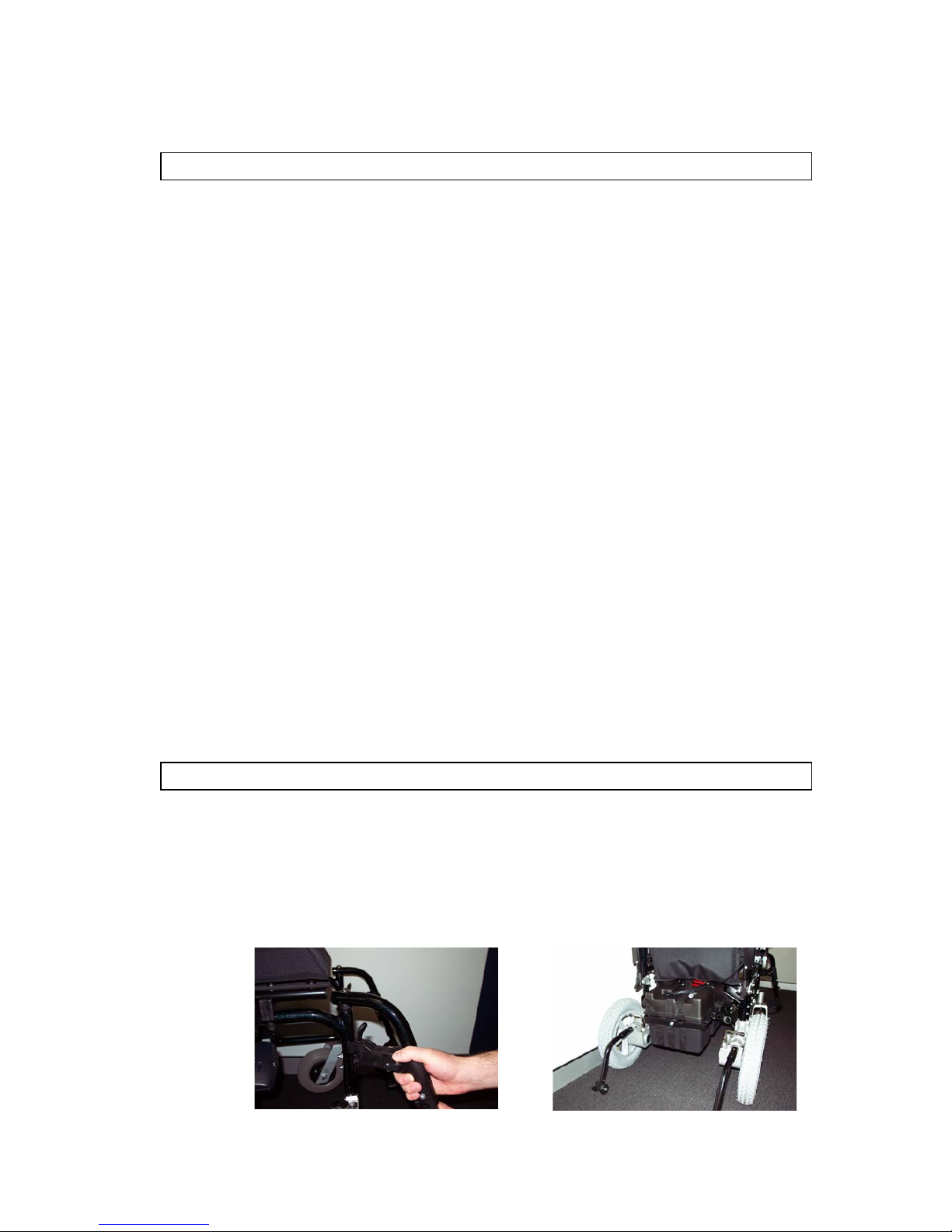
1. Mount the swing away legrests as shown in Fig 8.
2. Drive wheels, motor / gearbox assemblies are pre-installed as shows in
Fig 12.
Fig 12
Fig 8
8
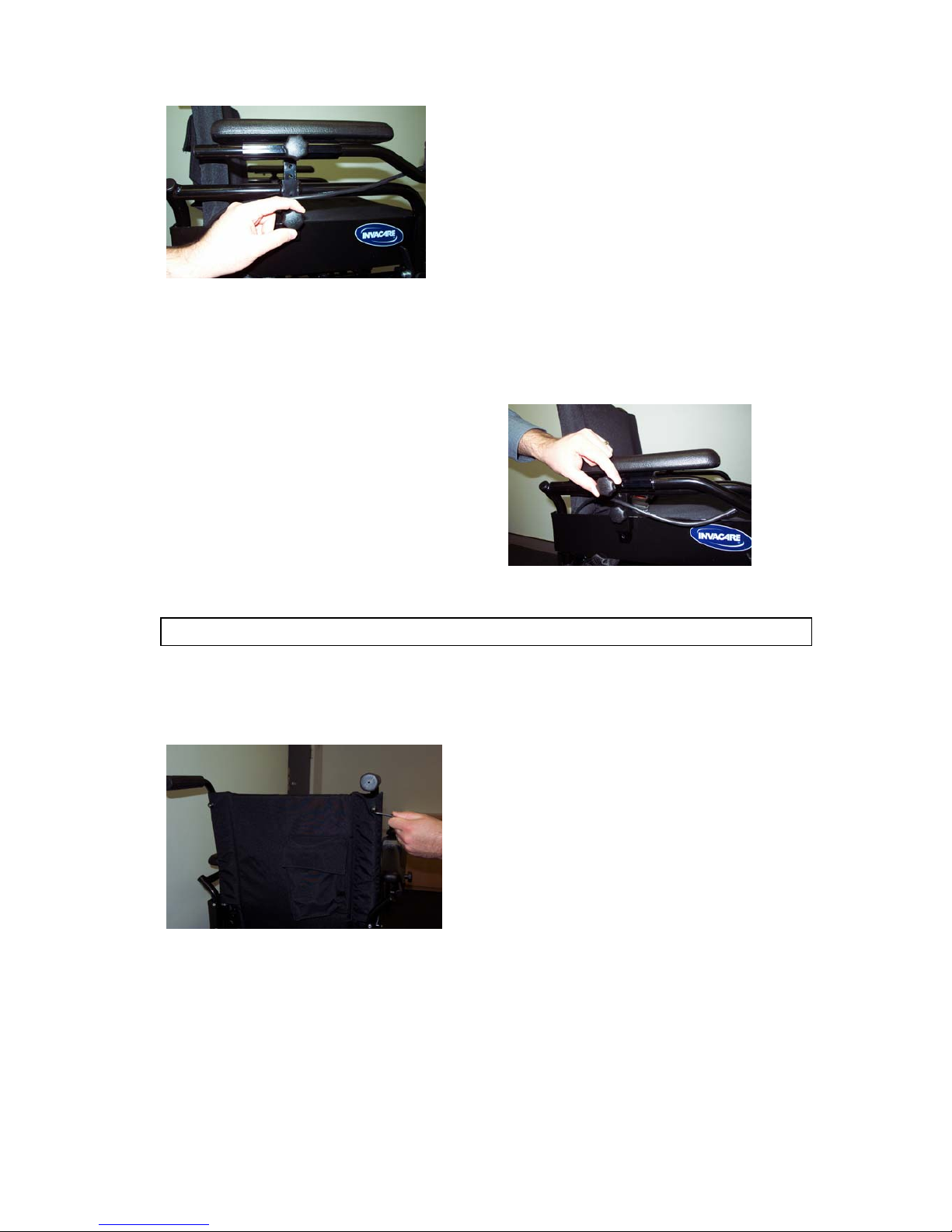
General Operation
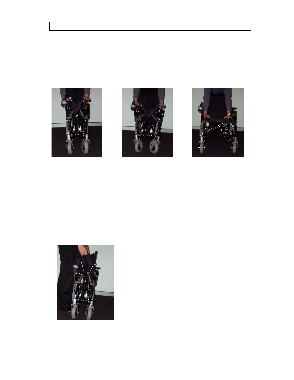
1. Ensure the cushion is not on the chair. Hold the two armrests with your
hands as Fig 13 shows.
2. Extend the armrests outwards as Fig 14 shows.
3. Push down on the seat rails to ensure the seat opens fully and locks into
the receivers on the wheelchair side frames as Fig 15 shows.
4. Swing the legrests around to the front of the chair and ensure that they lock
into place.
Fig 13 Fig 14 Fig 15
Fig 16
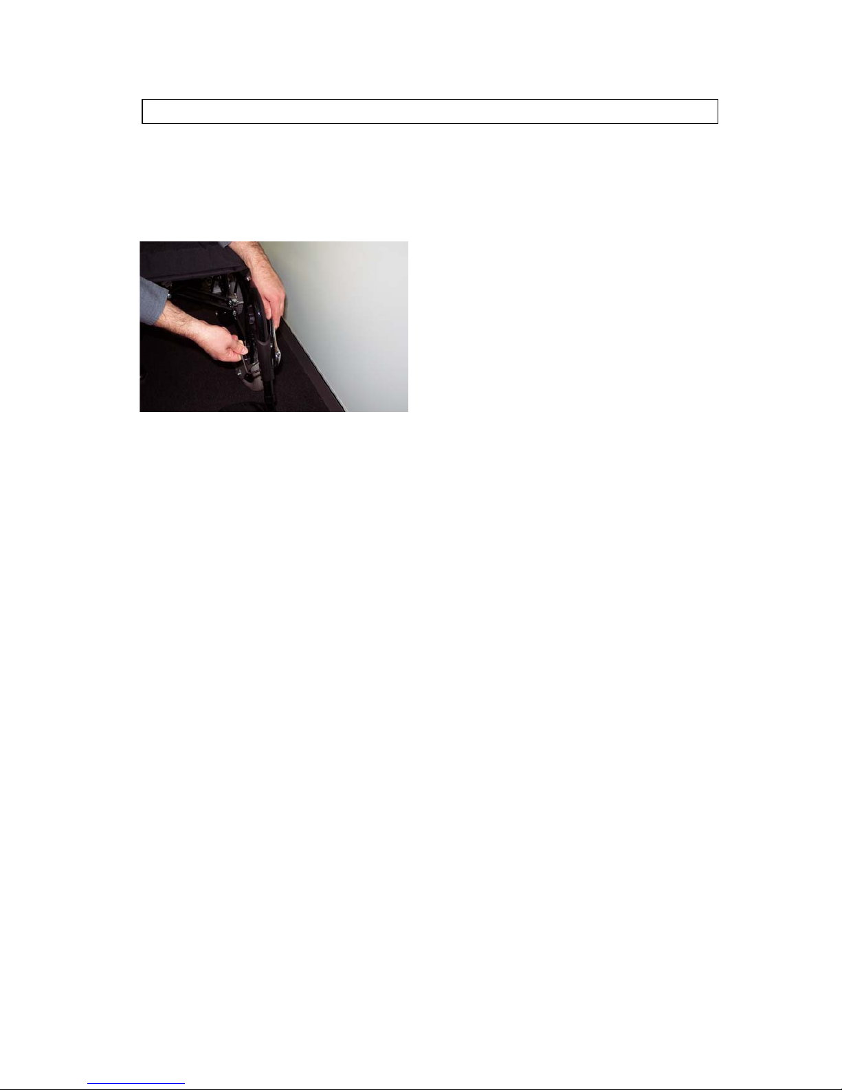
To fold the wheelchair for storage or transportation
1.
From the rear, release the battery box restraining strap. Unplug the rear battery box
and remove (red plugs). Unplug the front battery box from the main controller and remove
(see page 21 for more details).
2. Fold up the footplates and unlock the levers that position the legrests. Swing the
footplates and legrests away. Either leave the footplates in this position or remove them
completely by lifting each legrest vertically to clear the pivot bush as Fig 8 shows.
3. Take hold of the centre of the seat upholstery, one hand at the front and the other at
the rear. Pull up the seat upholstery vertically as Fig 16 shows.
9
After following all the steps in General Operation proceed with the following.
1. Insert the battery box with the external power connection towards the front
of the chair.
2. There are two batteries. Attach the wiring loom to each battery making sure
that the correct polarity is observed. Correct wiring is illustrated by a
placard, fixed in the battery box lid. Lift each battery with the lifting harness
attached into position, connect the power cables to the appropriate
plugs and ensure that the power cables are clear of obstacles when
replacing the battery box lid. Tighten the battery box securing strap.
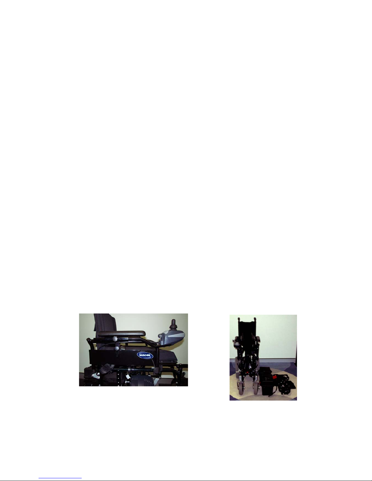
3. Slide the power control module into the mounting bracket under the armrest
and secure it into position. Your control module can be mounted either on
the left or right hand side of the chair. Should you wish to change the
mounting of the power module, your selling Dealer can assist as Fig 23
shows.
4. Ensure that all the power connections are correctly fitted.
Fig 23
Foldable frame, various quick
Release construction.
10
Special Features
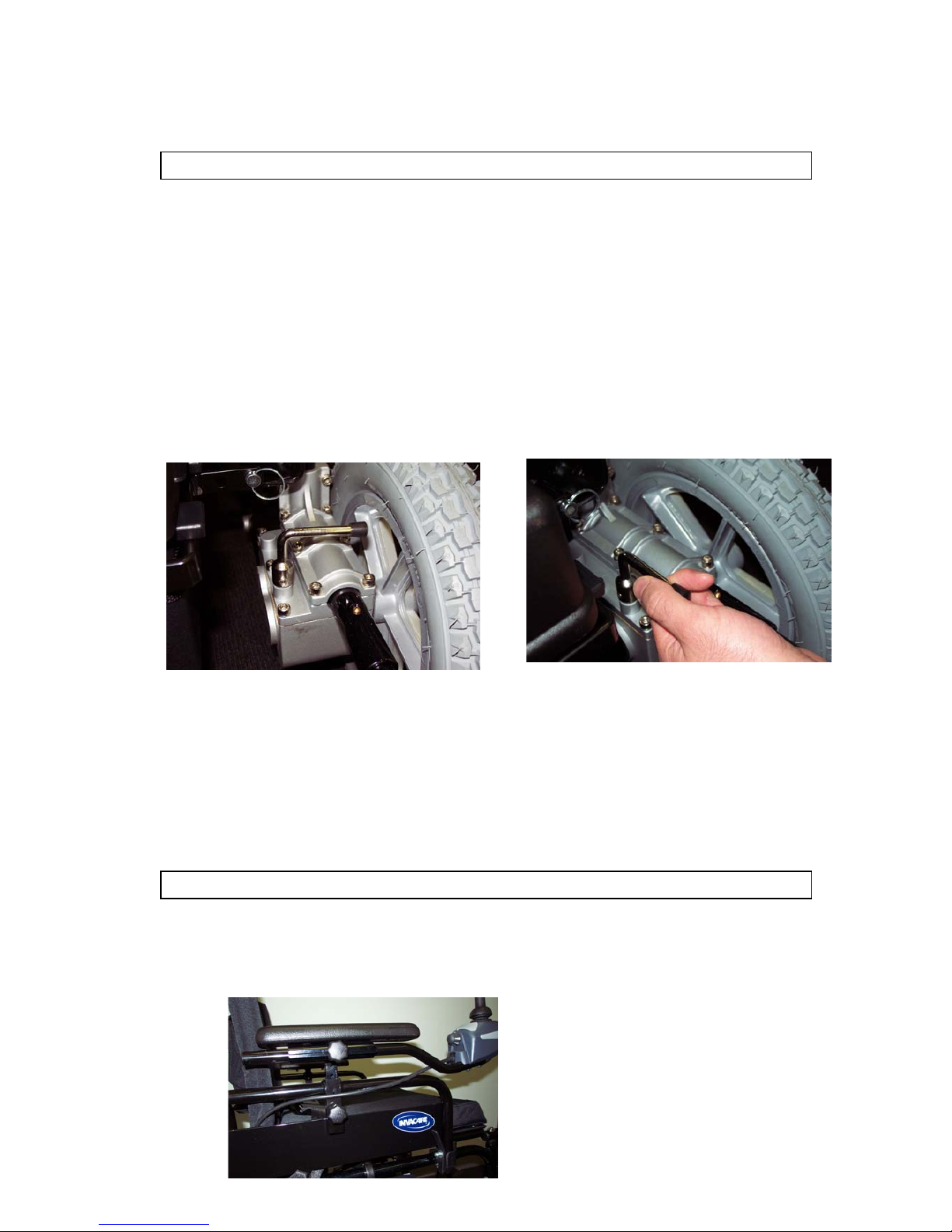
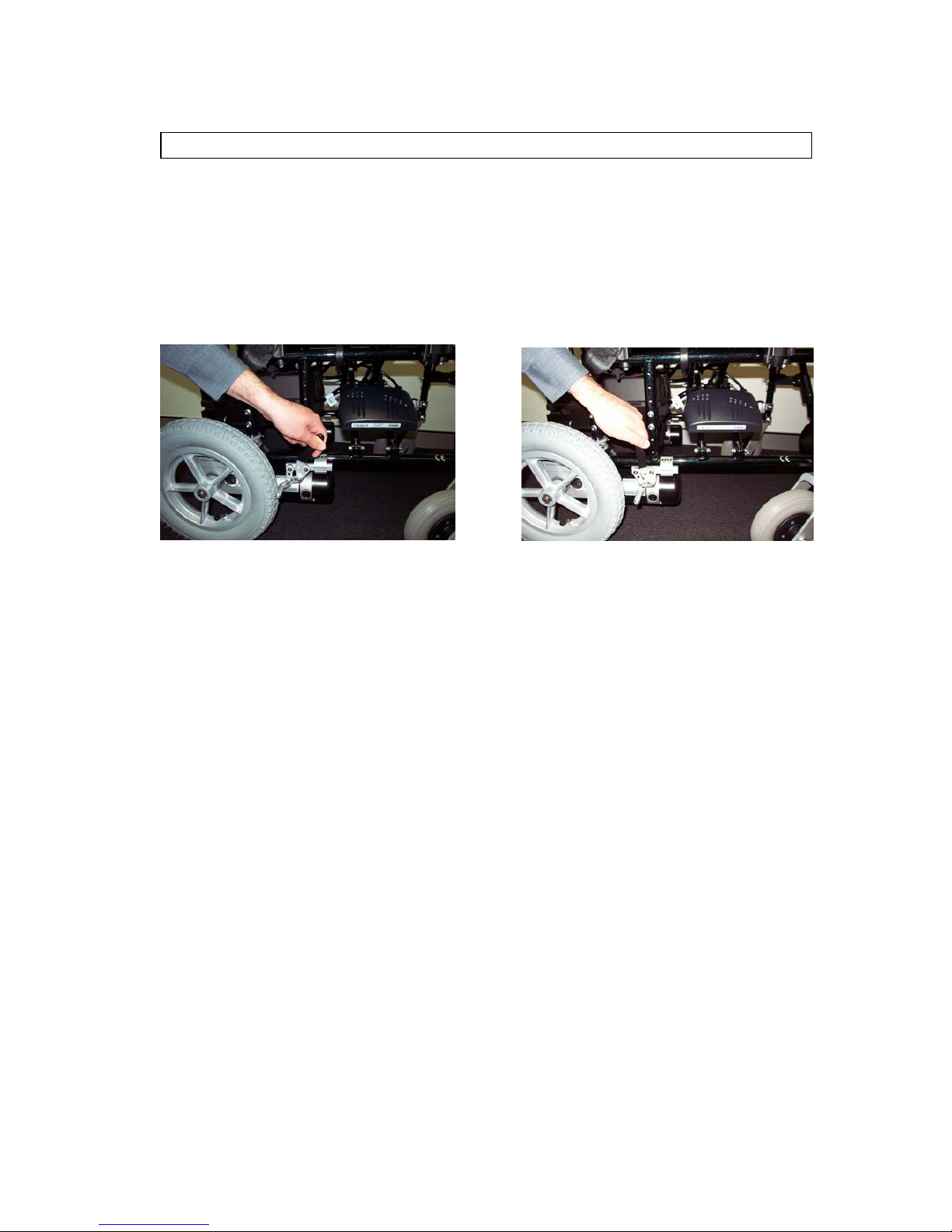
Freewheel levers
For your convenience, C650PW is equipped with two freewheel levers, see Fig
18 & 19. These levers allow you to disengage the drive motors and maneuver
the chair manually.
WARNING! DO NOT use you C650PW while the drive motors are disengaged
unless you are in the presence of an attendant! DO NOT disengage the drive
motors when your C650PW on an incline. The chair could roll down on its own,
causing injury !
To engage or disengage the freewheel feature:
1. Turn the freewheel levers outward to disengage the drive motors.
see Fig 18.
Fig 18 Driver disengaged Fig 19 Drive engaged
2. Turn the free wheel levers inward, to engage the drive motors, see Fig 19.
NOTE : It is important to remember that when your C650PW is in freewheel
mode, the braking system is disengaged.
Armrest
The height adjustable T-type armrest is provided as standard equipment on
C650PW power chairs, see Fig 3.
Fig 3
High adjustable armrest with
controller, various
ad
j
ustment function
11
Adjustment for the C650PW is facilitated by a screw as Fig 26 shows
Fig 26
Arm pad adjustable by levered screw
The controller unit can easily be adjusted to different position in order to meet
user’s demand. To adjust, turn the screw as Fig 25 shows.
.
Backrest
The backrest is adjustable by removing the four backrest cane securing screws
and selecting the required new height. The backrest canes are predrilled as Fig
32 shows.
Fig 32
WARNING! Replace worn or torn fabric immediately. Failure to do so may result
in a fall and severe injury to you.
12
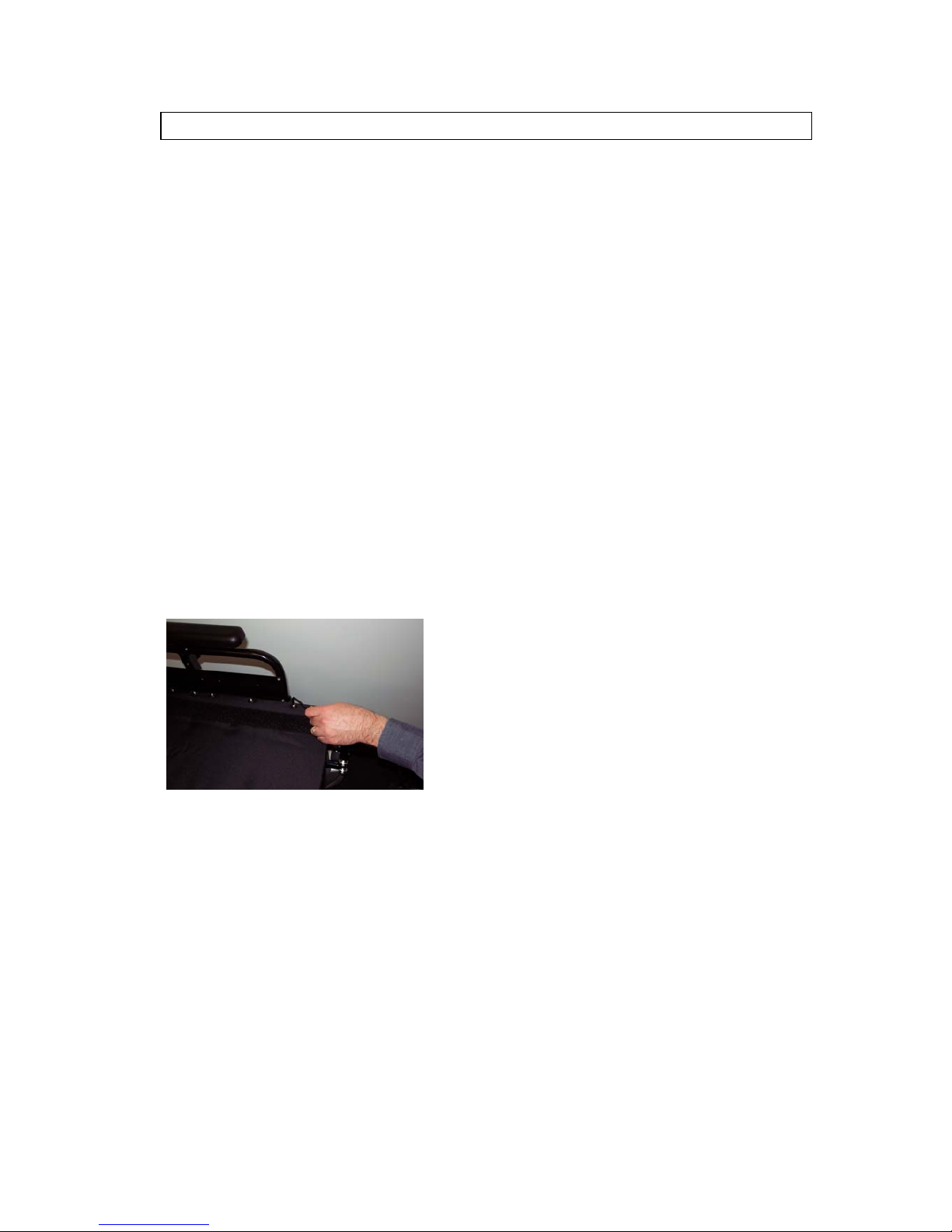
Seat
All Invacare chairs feature seat upholstery that can be tensioned. Whilst
there should be no adjustment necessary upon delivery of your new chair, over
time stretch could occur.
1. To re-tension the upholstery you must firstly remove all the locating screws
and washers from the chair seat rail on the side where the adjusting hook
and pile is located.
2. Slide out the aluminium pinch strip and adjust the hook and pile to increase
the upholstery tension.
3. Replace the pinch strip and using a punch or a similar tool, insert the tip
through the pinch strip and into a centre rivnut.
4. Lever the upholstery into position and secure a locating screw. If abnormal
pressure is required to align the locating screws then remove the upholstery
and readjust the hook and pile.
5. Repeat this operation until all the locating screws are in position. See Fig
29.
Fig 29
WARNING ! Replace worn or torn fabric immediately. Failure to do so may result
in a fall and severe injury to you.
13
Legrest
The C650PW standard equipment with swing-away & detachable legrest the footplate height adjustable. To adjust the height, remove the securing screws and
nuts from each side and slide the extension tube and foot plate up or down to the
desired height. Retighten the securing hardware as Fig 36 shows.
Fig 36
Swing away and detachable legrest
with extension tube
OPTIONS : There is elevating legrest as an option.
WARNING ! Never lift the wheelchair by the legrests. These parts are detachable
and will not bear the weight of this chair. Lift this chair ONLY by non-detachable
parts of the main frame.
14
Wheel Locks
Wheel locks are fitted to both drive wheels. Wheel locks should be engaged
whenever a transfer is made and / or when the wheelchair is stationary.
1. To apply the wheel locks pull the hand lever upward as Fig 39 shows.
2. To release the wheel locks push the hand lever downward as Fig 38 shows.
Fig 38 To release wheel lock Fig 39 To apply wheel lock
3. DO NOT use the wheel locks to slow the wheelchair whilst descending an
incline.
4. Wheel locks can be adjusted as tyre wear increases. To adjust, loosen the
frame mounting clamp and slide the wheel lock upward. Retighten the
clamp while wheel lock engages to correct position. Your selling dealer can
assist with adjustment.
Please note: When the chair’s motor gearbox is engaged the motor-gearbox will act as an
electronic magnetic brake.

15
Safe driving techniques
Driving your Chair
Before transferring to your chair from either the front or the side ensure that:
1. The chair is switched off.
2. The wheel locks are engaged.
3. Swing away the armrests and legrests if appropriate.
4. The battery charger is disconnected from both the chair and the mains.
After transferring make sure that you are comfortably positioned and that the
legrests and armrests have been adjusted to suit your needs. The position of the
joystick should be easy to reach so as to eliminate muscle fatigue during driving.
TO COMMENCE :
1. Set the speed control of the chair to SLOW as described in the
CONTROLLER CONTROL UNIT OWNER'S MANUAL following this manual.
2. Release the wheel locks.
3. Press the “on / off ” switch.
4. Allow two seconds to elapse before engaging the joystick. This is a safety
feature to prevent sudden starts.
5. Push the joystick gently forward applying a steady even pressure. The
further you push the joystick, the faster the chair will go. The chair will stop
when you return the joystick to the neutral or vertical position.
6. Directional control is achieved by gently swivelling the joystick in the
direction you wish to go. Pull back to reverse.
7. The controller can be programmed to give you the best feel for all driving
situations and only needs a light touch to respond.
In the case of an emergency, let the joystick go and the chair will come to a
stop.

16
Safe Driving
1. Never drive at a speed greater than your ability to safely control your chair.
Remember that wet or loose surfaces need greater care and control.
2. Always turn the chair off when transferring or while the chair is stationary for
long periods.
3. Avoid jerky stop / start motions as this will result in excessive current draw
from the batteries, increased tyre wear and the rapid wearing of the
gearbox and motors.
4. Keep your chair clean from sand and salt water.
5. Ensure that the tyres are correctly inflated.
Indoor / Outdoor Driving
When driving indoors keep the level of speed to a minimum to avoid the risk of
collision.
For outdoor driving be wary of wet surfaces, loose sand, large kerbs and potholes.
A little practice will ensure you understand the capabilities of your chair and enable
you to overcome the most common obstacles en-counted when driving.
If operating your chair on the roads please check with your local Police
Department regarding necessary identification and safety devices such as
reflectors.
Chair Operation on surfaces that require Special Care
When driving up or down ramps it is recommended that the user:
1. Visually checks to see if the angle of the slope is less than 15 degrees.
2. Checks to see that the ramp surface is roughened to prevent slippage.
3. Ensures that the ramp surface is correctly in line with the tyres and is wide
enough to allow the tyres to pass freely along the ramp.
If the ramp meets these conditions, it is recommended that the user drives the
wheelchair slowly up or down the ramp, ensuring that the chair is driven in the
centre of the ramp tracks. If possible, have an assistant monitor the chairs’
progress, and prevent tipping of the chair by holding the push handles at the back
of the seat.
If the ramp does not meet these conditions, it is recommended that
alternative methods for climbing and descending be found.

17
Chair Response
Should the chairs’ response not be to your satisfaction, ask your Dealer to adjust
the programme to a level at which you are comfortable. This programme can be
altered at anytime to either increase the response rates in line with your improved
motor skills or to lower the rates to level at which you feel comfortable and in
control.
Kerbs
For power chairs with microcellular (hard) front tyres it is recommended that before
the user attempts to climb or descend a kerb that the user visually checks the
height of the kerb to ensure that it does not exceed 35mm (1 1/2”) in height.
If the kerb height is less than 35mm, the user should approach the kerb at right
angles to the kerb line at a slow speed, climb or descend the kerb slowly so as to
keep the chair under control. If climbing the kerb the user may find it easier to
reverse the chair up the kerb.
If the kerb height is greater than 35mm, it is not recommended that the user climb
or descend the kerb. Should there be any doubt then an assistant should be
called to supervise the operation.
Steep Slopes
When the power wheelchair is to be operated up and down steep slopes, it is
recommended that the user:
1. Visually checks to see if the angle of the slope is less than 15 degrees.
2. Checks that the slope surface is roughened to prevent slippage.
If the slope meets these conditions, it is recommended that the user approaches
the slope at a slow speed, keeping the chair under control at all times. It may be
preferable to track across the slope so as to decrease the steepness of the
descent providing that the surface of the slope is wide enough and suitable to
prevent slippage.
If possible have an assistant monitor the chairs’ progress, and prevent tipping by
holding the push handles at the back of the chair.
WARNING : If the slope does not meet these conditions, it Is recommended that
the user does not climb or descend the slope.

18
Batteries and Charging
When your batteries are fully charged you should have sufficient power to give you
all the mobility required in a day - It is important that you understand how your
batteries and charger work.
Battery Maintenance
Batteries supplied are a Gel type battery, and require no maintenance with the
exception of maintaining a full charge. Do not partly charge the battery.
check the battery water level once a week and top up, if necessary, with distilled
water after charging, to cover the separator plates by 6mm (1/4”), no more.
If the batteries are the dry cell type there is no maintenance required.
Charging the Batteries
1. Batteries should be charged every night in a well ventilated room.
2. DO NOT place the power wheelchair near radiators or open fireplaces
whilst charging.
3. DO NOT smoke or permit naked flames in the immediate vercinity.
4. Turn the chair controller power off before charging.
5. It is advisable that the batteries be charged for a minimum of 10 hours per
night to ensure a full return to the batteries storage capacity. The battery
charger is an automatic current limiting device and will shut off when the
batteries are fully charged.
Charging the batteries :
1. Position C650PW power chair next to a standard wall outlet.
2. It is done by connecting the battery charger to the wheelchair input battery
charging socket.
3. Connecting the battery charger to a standard wall power outlet.
4. Switching the power on.

19
During the recharge:
1. Whilst the batteries are being recharged, a red light will appear on the
battery charger, indicating that the power is connected and charging is in
progress.
At the end of the recharge cycle:
1. A green light will appear on the charger. This indicates that the batteries
are fully charged and ready for use.
2. If fitted, the battery charge level indicator on the controller should also
show a full charge when switched on.
When do the batteries need recharging ?
When the batteries fall below 80% of the maximum charge level, the “on / off” lamp
on the controller will flash. This indicates that whilst you have some reserve
power, the batteries should be recharged.
Note:
1. Do not use batteries other than the recommended type for your chair and
never use a charger other than the one supplied for the purpose.
2. If the chair is not used for a long period of time (e.g., school holidays,
hospitalisation, or when vacationing) arrange to have the batteries charged
for at least one day (10 hours) every month, minimum.
3. Periodically, check the battery terminals are clean and the connections are
tight. Smear a thin film of petroleum jelly on the terminals to guard against
corrosion. Always wash your hands after handling batteries.
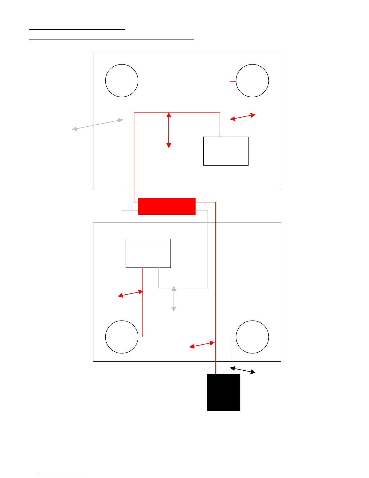
INVACARE – Wire diagram Date : August 20, 2004
C650PW(EA) power chair with Shark controller
Connector .Red
.
Black
+
+
-
+
+
White
Red
Red
Cut-out switch
Cut-out switch
Red
White
Red
Controller Lead .Black
.
Front

21
Replacing the batteries
CAUTION ! - if you have doubts about your ability to lift any components, it
is recommended that you seek assistance so as to avoid injury.
1. Turn the power off .
2. Disconnect the battery connection plug at the front of the battery tray.
3. Release the securing belt holding the battery box.
4. Disconnect the battery connection cables located in the battery box.
5. Lift the rear battery out of the battery box by using the lifting strap.
6. Slide the front battery to the rear of the battery box and remove the battery
as in step 4.
7. Undo the terminal lugs, noting the polarity of the lugs. Remove the wiring
loom.
8. Repeat step 6 for the other battery.
9. Inspect the terminals on the wiring loom and the lugs on the replacement
batteries to make sure they are clean. If they are not, clean with a warm
solution of bicarbonate of soda (one dessert spoon) and water (approximately five litres). It is important that you wash your hands afterwards.
10. Connect the terminal lugs on the wiring loom to the new batteries, observing
the polarity of the lugs as noted before.
11. Place the new batteries back into the battery box and rejoin the connectors.
12. Replace the battery box lid and secure the retaining belt.
13. Reconnect the power cable.
For maximum performance it is strongly recommended that you replace both
batteries at the same time.
22
Tyre and Tube
You should check the pneumatic tyres air pressure at least once per week. This
will prolong the life of your tyres as well as help ensure the perfect operation of
your chair. If you should have a flat tyre, you should replace the tube.
Replacement tyres and tubes are readily available at the dealer shop where you
purchased your C650PW.
Front wheels : C650PW come with 200x50mm pneumatic tyres, pressure 36
psi in each tyre as standard equipment.
OPTION: 200 x 50mm airless tyres.
Rear wheels : C650PW come with 12-1/2" x 2-1/4" pneumatic tyres.
Pressure 40 psi or 280 KPA in each tyre is standard equipment.
OPTION: 12-1/2" x 2-1/4" airless tyres.
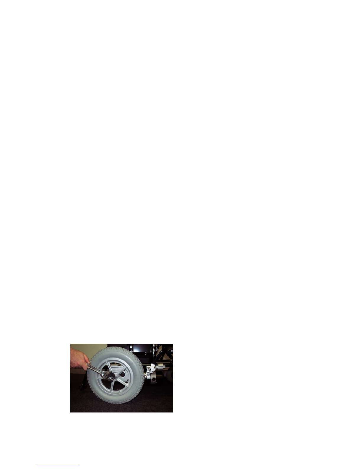
WARNING ! Make sure the tyre is completely deflated before attempting repair.
Follow these easy steps for a quick and safe repair:
1. Completely deflate the tyre if pneumatic.
2. Use an ratchet and socket to remove the drive wheel screw from the centre
hub of the wheel. See Fig 41.
3. Pull the wheel off of the axle.
4. Separate the tyre and tube from the rim.
5. Remove the old tube and/or tyre and replace it with a new tube and/or tyre.
6. Slide the wheel back onto the shaft.
7. Install the drive wheel nut into the centre hub and tighten.
8. Inflate the tyre pressure to maximum 36 psi for front wheel.
Inflate the tyre pressure to maximum 40 psi for rear wheel.
Fig 41 Rear drive wheel
Screw removal
Rear wheel fixing screw
Must be tightened by
1000 kgf .cm torsion
23
Maintenance, Cleaning & Fault finding
An electric wheelchair needs some basic attention to ensure it provides reliable
service. We recommend that the user ensures that the power wheelchair is
checked regularly for maintenance requirements and receives a thorough and
annual maintenance check up.
We recommend that the chair has at least one full service from an authorised
dealer once a year. If you notice any irregular aspect of your chair phone your
nearest authorised dealer for assistance. They will advise if the chair should be
returned for repairs. If the chair is to be returned, they will advise on the
availability of replacement units, and the required method of packing and shipping.
Annual Maintenance
We recommend that the chair has at least one full service per year from an
Authorised Dealer. This help ensure your power chair is functioning properly and
helps prevent future complications. This should include:
1. Checking the tyres and tubes.
2. Checking the batteries and terminals.
3. Checking the controller programme for the user’s needs.
4. Checking the wheelchair frame.
5. Checking the upholstery condition.
Regular Maintenance and Cleaning
1. Avoid knocking or bumping the controller, especially the joystick.
2. Avoid prolonged exposure of your power chair to extreme conditions, such
as heat, cold, or moisture.
3. Keep the controller clean.
4. Check all controller connectors are tight and secured properly.
5. Never hose off your power chair or place it in direct contact with water.
6. Keep the upholstery and frame clean by wiping with a soft cloth, particularly
after driving through wet, sandy or muddy conditions. Do not use harsh
abrasive materials when cleaning. Do not apply liquid cleaners or solvents
directly to the control box, battery charger or any electrical connections.
7. Keep wheels free from lint, hair, sand and carpet fibres.

24
8. Lightly oil axle pin, wheel axles and bearings once every three months.
9. Keep rear wheel tyres at correct inflation levels to maximum 40 psi, (or
275 KPA), if use pneumatic tyre in front inflation levels to maximum 36 psi.
10. Use only recommended batteries and have batteries changed only by
Qualified Dealers.
11. Charge batteries regularly. Make sure the charger lead plugs are engaged
properly in the sockets. Do not disconnect by pulling the cord.
12. With the controller turned off, check the joystick. Make sure it is not bent or
damaged and that it returns to centre when you release it. Check the
rubber boot around the base of the joystick for damage. Visually inspect
the boot. Do not handle or try to repair it. See authorized dealer if there is
any problem.
13. Visually inspect the controller harnesses. Make sure that they are not
frayed or cut or have any wires exposed. See authorized dealers if there is
a problem with any of these harnesses.
14. Ensure that all parts of the controller system are securely fastened to your
C650PW. Do not over tighten any screws.
Storage
Your wheelchair should be stored in a dry place free from temperature extremes.
When storing, disconnect the batteries from the power chair. See "Batteries and
Charging" in this manual. If you fail to store the unit under the above conditions,
the frame can rust, and the electronics can be damaged.

25
FAULT FINDING CHECK LIST :
Problem: The controller light flashes.
Action: If the lamp flashes immediately when the power is switched on and
the joystick is engaged, switch the power off, wait a few seconds,
then switch on again. Wait for two seconds before engaging the
joystick.
Problem: The controller lamp flashes slowly while driving.
Action: The slow flashing means that the battery charge level is low and
should be placed on charge as soon as practicable.
Problem: The controller lamp flashes continuously and the chair will not
operate.
Action: The continuous flashing of the lamp means there may be a major
problem. Switch the power off, disengage the wheel clutches and
seek assistance. Contact your Dealer and advise of the problem.
Problem: The red light on the battery charger fails to illuminate when the
power is connected to it.
Action: Check that all the leads have been properly connected and the
mains power is turned on. If this doesn’t cause the red light on the
charger to illuminate, turn the mains power off, disconnect the lead
from the mains to the battery charger. Contact your Dealer and
advise of the problem.
Problem: The chair is difficult to steer.
Action: First, check the tyre pressure of all the tyres. Second, check to see if
both the clutches are engaged correctly.
Note :
If you detect that there are problems with the motors, the battery charger, the
controller or damage to the power wheelchair frame, it is recommended that you
contact the nearest Authorised Service Agent or your Distributor.
If you notice any other irregular aspect of your chair or if it fails to respond after
making some of the above inspections, phone your nearest Authorised Service
Agent or Dealer for assistance. They will advise if the power wheelchair should be
returned for repairs. If the chair is to be returned, they will advise on the
availability of replacement units, and the required method of packing and shipping.

26
Limited Warranty
This is to certify that the Invacare C650PW power chair is guaranteed against
defects in materials and workmanship and free of fault, wear and tear excluded, as
follows :
There will be ONE YEAR limited warranty from the date of purchase for any
of below parts found, wear and tear excluded.
• Electric motors and battery charger
• Micro processor controller
• Foot rigging
• Manual brakes and hardware
• Armrests
• Cross braces
• Backrest canes
Warranty exceptions :
Motor-the commentator of the motor is not warranted if the damage is
caused by not replacing the motor brushes after heavy wear to the brushes.
Motor brushes are wear items and are not warranted.
The chair side frames are guaranteed for a period of FIVE YEARS from
date
of purchase.
Warranty exclusions:
• Batteries
• Tyres and tubes
• Upholstery and seating
• Repairs and/or modifications made to any part without specific prior
Written consent from Invacare Australia Pty Ltd
• Circumstances beyond the control of Invacare Australia Pty Ltd
• Labor, service calls, shipping, and other charges incurred for repair of
The product unless specifically authorized by sells dealers.
Damage caused by :
• Battery fluid spillage or leakage
• Abuse, misuse, accident, or negligence
• Improper operation, maintenance, or storage
• Commercial use, or use other than normal

27
This guarantee is subject to the following conditions :
1. This warranty is extended only to the original purchase/user of Invacare
products.
2. The Company will not accept responsibility if the fault was caused by
misuse or failure to observe the instructions in the User’s Manual.
3. If a fault develops, it is the responsibility of the owner to immediately
notify the company or the Distributor from whom the chair was
purchased.
4. All costs associated with the freight of the chair or any faulty components
are the responsibility of the owner.
5. Labor charge incurred in the installation or repair of the above-mentioned
parts plus all freight charges are not included in the warranty
6. Any parts found to be defective due to faulty workmanship and / or
materials will be renewed or repaired at the Company’s discretion
without charge to the owner of the chair.
7. The guarantee will be voided if any unauthorized repair service or parts
alteration has been made.
8. The company will not warranty the frame or any parts damaged when the
maximum weight limited of one hundred kilograms is exceeded.

28
Customer Service Support
Please contact nearest Invacare distributors for any queries concerning your
wheelchair and/or electric wheelchair.
Before calling:
Please fill in the following information. The details below will help us
assist you faster and ensure we provide you with the best advice
concerning your power wheelchair.
Series Number ..................................
Model ................................................
Date of purchase ...............................
NOTICE :
The information and specification of C650PW contained in this User’s
Manual is subject to change without prior notice.
No part of this document may be photocopied, reproduced, transmitted,
transcribed, stored in a retrieval system or translated to another language or
computer language, in any form or by any means, electronic, mechanical,
magnetic, optical, chemical, manual or otherwise without prior written consent of
Invacare Australia. All rights reserved.
Invacare recommends you use Invacare accessories and parts with Invacare
products. Replace any worn out parts immediately.
29
CONTROLLER CONTROL UNIT OWNER'S MANUAL
Hydra
Folding Power Wheelchair
September 2004. All prices quoted are GST exempt & exclude delivery. All information, including pricing and specifications, subject to change without prior
notice. Photographs are for illustration purposes only & may vary from product depiction.
Invacare
®
, and Yes, you can., are trademarks of Invacare Corporation. © 2001 Invacare Corporation.
Invacare Australia. 1 Lenton Place North Rocks NSW 2151 , Australia.
Phone (02) 8839 5333. Fax (02) 8839 5353
 Loading...