

Invacare HomeFillII AW Service Manual
Service Manual
0434
HomeFill® II AW
Compressor
NOTE: Compressor shown without cylinder attached.
DEALER: Keep this manual. The
procedures in this manual MUST be
performed by a qualified technician.
For more information regarding
Invacare products, parts, and services,
please visit www.invacare.com
REFERENCE DOCUMENTS
DANGER
Risk Of Death, Injury, Or Damage
Improper use of the product may cause death, injury or damage. This
manual contains important information for the safe operation and use
of this product.
- DO NOT use this product or any available optional equipment without
first completely reading and understanding these instructions and any
additional instructional material such as user manuals, service manuals
or instruction sheets supplied with this product or optional equipment.
- If you are unable to understand the warnings, cautions or instructions,
contact a healthcare professional, dealer or technical personnel before
attempting to use this equipment.
- THE PROCEDURES IN THIS SERVICE MANUAL MUST BE
PERFORMED BY A QUALIFIED TECHNICIAN.
REFERENCE DOCUMENTS
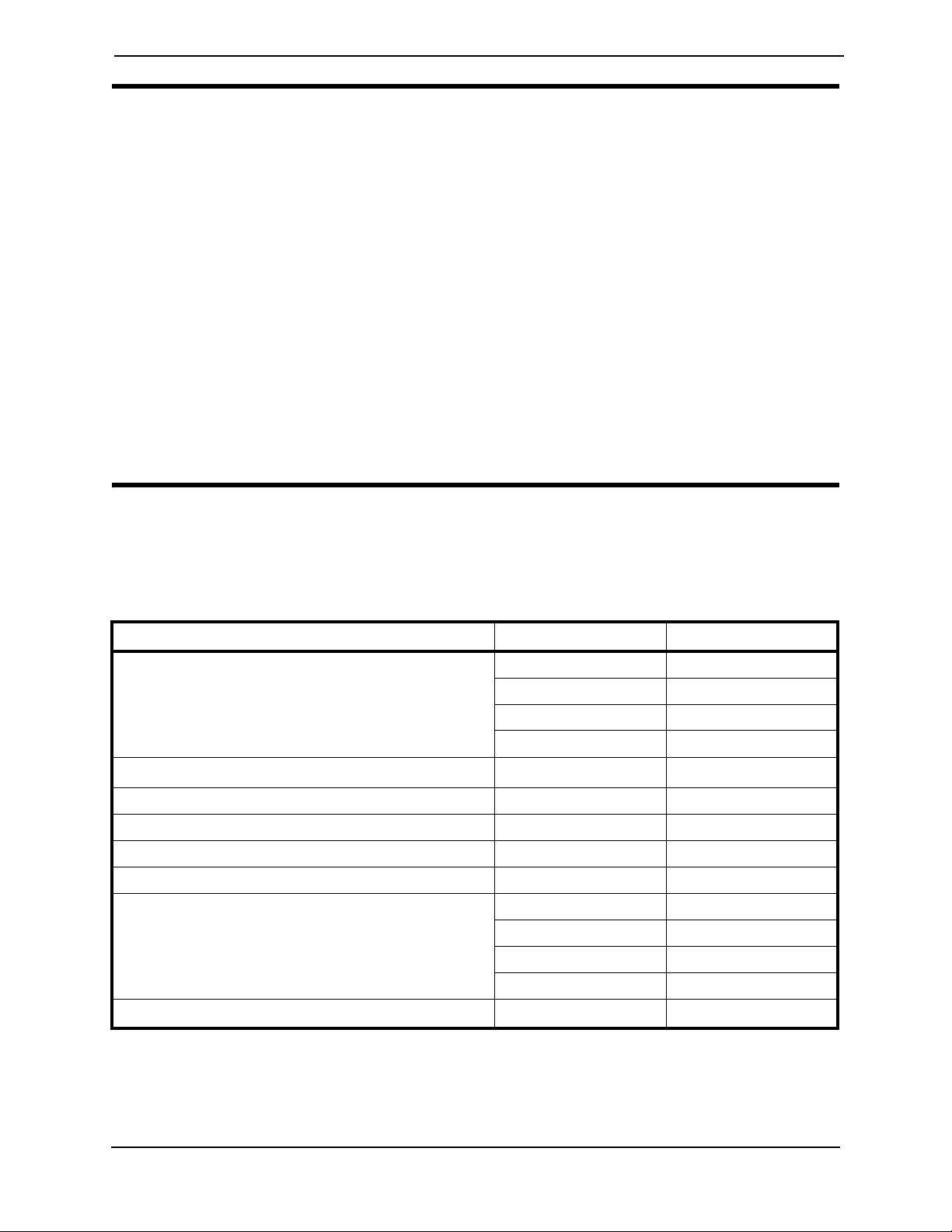
Refer to the following table for part numbers of additional documents which are
referenced in this manual.
MANUAL PART NUMBER LANGUAGES*
HomeFill AW Compressor User Manual 1116444 English
1145804 Northern
1145805 Southern
1145806 Scandinavian
®
Platinum
Platinum Concentrator Service Manual 1118396 English
Perfecto
™ AW & VAW Concentrator User Manual 1163145 Northern
2
Concentrator User Manual
1134866 English
1141491 Northern
1141492 Southern
1141493 Scandinavian
1163146 Southern
1163147 Scandinavian
1160877 English
Perfecto
Concentrator Service Manual 1154245 English
2
*NOTE: Northern languages include English, Czech, French, German, Italian and Polish.
Southern languages include English, Dutch, French, Greek, Italian, Portuguese and Spanish.
Scandinavian languages include English, Danish, Finnish, Norwegian and Swedish.
HomeFill® II AW Compressor 2 Part No 1154316

TABLE OF CONTENTS
TABLE OF CONTENTS
REFERENCE DOCUMENTS ................................................................. 2
SPECIAL NOTES ................................................................................ 6
TECHNICAL DATA ........................................................................... 7
LABEL LOCATIONS ........................................................................... 8
GENERAL ....................................................................................... 10
Symbols.................................................................................................................................................................................. 10
Symbols in the Manual ........................................................................................................................10
Symbols on the Product .....................................................................................................................10
Intended Use........................................................................................................................................................................ 11
SECTION 1: GENERAL GUIDELINES .................................................. 13
Operating Information......................................................................................................................................................13
Handling................................................................................................................................................................................. 14
EMC Information................................................................................................................................................................ 15
SECTION 2: CONCENTRATOR VERIFICATION AND
MAINTENANCE ............................................................................. 16
Performance Verification.................................................................................................................................................16
Connecting the Compressor to the Concentrator................................................................................................ 17
SECTION 3: CHECKLIST AND CYLINDER INSPECTION ...................... 18
Compressor Operation Checklist................................................................................................................................ 18
Cylinder Prefill Inspection................................................................................................................................................ 18
Hydrostatic Testing Date...................................................................................................................19
External Examination ..........................................................................................................................19
SECTION 4: COMPRESSOR OPERATION ........................................... 20
Connecting/Disconnecting Cylinder to/from Compressor..................................................................................20
Connecting the Cylinder to the Compressor...............................................................................20
Disconnecting Cylinder From Compressor ..................................................................................22
Turning the Compressor On and Off......................................................................................................................... 23
SECTION 5: CABINET ASSEMBLY .................................................... 25
Removing/Installing the Cabinet .................................................................................................................................... 25
Removing ...............................................................................................................................................25
Installing..................................................................................................................................................25
Removing/Installing the Cabinet Filter Grid............................................................................................................... 26
Removing ...............................................................................................................................................26
Installing..................................................................................................................................................26
Replacing Non-Skid Adhesive Back Pad...................................................................................................................... 27
Replacing Foam Gasket....................................................................................................................................................27
Part No 1154316 3 HomeFill® II AW Compressor

TABLE OF CONTENTS
TABLE OF CONTENTS
SECTION 6: PANEL ASSEMBLY ........................................................ 28
Replacing Exhaust Fan.......................................................................................................................................................28
Removing/Installing Control Panel................................................................................................................................29
Installing................................................................................................................................................................................. 29
Testing/Replacing the Power Switch............................................................................................................................ 31
Replacing Circuit Board ................................................................................................................................................... 32
Replacing Accumulator Assembly.................................................................................................................................33
SECTION 7: BASE COMPONENTS ..................................................... 34
Replacing the Fuse.............................................................................................................................................................. 34
Removing/Installing the Power Inlet............................................................................................................................. 35
Removing ...............................................................................................................................................35
Installing..................................................................................................................................................35
Replacing Hour Meter......................................................................................................................................................36
Replacing O2 Inlet Connector/Inlet Connector Dust Cap...................................................................................36
Replacing Transformer.....................................................................................................................................................37
Testing/Replacing Capacitor ........................................................................................................................................... 38
Testing ....................................................................................................................................................38
Replacing Capacitor.............................................................................................................................39
Removing Connector Fillport Dust Cover and Lanyard - Units Manufactured
Before 10/03/2005............................................................................................................................................................. 40
Removing ...............................................................................................................................................40
Removing/Installing Connector Fillport Dust Cover and Lanyard - Units Manufactured
After 10/02/2005................................................................................................................................................................ 41
Replacing the High Pressure Switch.............................................................................................................................42
Replacing Burst Disk Fitting............................................................................................................................................ 42
SECTION 8: BASE REPLACEMENT .................................................... 44
Disassembly.......................................................................................................................................................................... 44
Reassembly...........................................................................................................................................................................50
SECTION 9: MOTOR REPLACEMENT ................................................ 52
Disassembly...........................................................................................................................................52
Reassembly ............................................................................................................................................57
SECTION 10: COMPRESSOR REPLACEMENT ..................................... 59
HomeFill Units Manufactured Before 8/1/05 ............................................................................................................ 59
Disassembly...........................................................................................................................................59
Assembly of New Motor/Pump Assembly .....................................................................................64
Reassembly ............................................................................................................................................66
HomeFill Units Manufactured After 8/1/05............................................................................................................... 68
Disassembly of HomeFill Units.........................................................................................................68
Reassembly of HomeFill Units ..........................................................................................................73
HomeFill® II AW Compressor 4 Part No 1154316

TABLE OF CONTENTS
TABLE OF CONTENTS
SECTION 11: TIMING BELT REPLACEMENT ...................................... 75
Disassembly.......................................................................................................................................................................... 75
Reassembly...........................................................................................................................................................................80
SECTION 12: WIRING ASSEMBLIES ................................................... 81
Replacing Wiring Assemblies.......................................................................................................................................... 81
Full View of Wiring Harnesses .........................................................................................................81
Replacing Transformer Assembly.....................................................................................................81
Replacing Bleed Resistor Assemblies ..............................................................................................82
Replacing HFII Assembly Wire Harness.........................................................................................83
SECTION 13: TROUBLESHOOTING/CYLINDER FILL TIMES .................. 85
Indicator Light Explanation.............................................................................................................................................. 85
Troubleshooting .................................................................................................................................................................85
Cylinder Fill Times............................................................................................................................................................. 87
Leak Test............................................................................................................................................................................... 87
Cylinder Fill Test ................................................................................................................................................................88
HomeFill 2000 psi Switch/P.C.B. Shut Down Test.................................................................................................. 92
SECTION 14: MAINTENANCE .......................................................... 94
Wear and Tear.................................................................................................................................................................... 94
Service Life............................................................................................................................................................................ 94
Cleaning/Replacing the Cabinet Filter..........................................................................................................................95
Cleaning Cabinet ................................................................................................................................................................ 95
Verification Process - Invacare HomeFill Compressor..........................................................................................96
Function Test.......................................................................................................................................................................97
Verification Process - Invacare HomeFill Cylinder.................................................................................................. 98
Function Test.......................................................................................................................................................................99
SECTION 15: AFTER USE ............................................................... 100
Disposal...............................................................................................................................................................................100
CUSTOMER SERVICE AND WARRANTY INFORMATION ................. 103
Part No 1154316 5 HomeFill® II AW Compressor

SPECIAL NOTES
SPECIAL NOTES
DANGER
Risk Of Death, Injury Or Damage From Fire
Textiles, oil or petroleum substances, grease, greasy substances and other
combustibles are easily ignited and burn with great intensity in oxygen enriched air
and when in contact with oxygen under pressure. To avoid fire, death, injury or
damage:
- DO NOT SMOKE while using this device.
- DO NOT use near OPEN FLAME or IGNITION SOURCES.
- DO NOT use any lubricants on the compressor unless recommended by Invacare.
- NO SMOKING signs should be prominently displayed.
- Avoid creation of any spark near oxygen equipment. This includes sparks from
static electricity created by any type of friction.
- Keep all matches, lighted cigarettes, electronic cigarettes or other sources of
ignition out of the room in which this compressor is located and away from where
oxygen is being delivered.
- Keep the oxygen tubing, cord, and compressor out from under such items as
blankets, bed coverings, chair cushions, clothing, and away from heated or hot
surfaces including space heaters, stoves, and similar electrical appliances.
- DO NOT allow oil from your hands or other sources to come into contact with the
compressor coupling or cylinder fittings. These substances may become flammable
in the presence of oxygen and cause injury. Avoid touching the cylinder fitting
whenever possible. Example of items to avoid are hand creams or lotions, cooking
oils, suntan oils or sunblocks and similar oily products. If you use these types of
products Invacare suggests you wash your hands prior to using the HomeFill unit.
If the cylinder fitting should come in contact with such substances it should be
cleaned off with a damp cloth prior to connecting it to the compressor.
- NEVER oil or lubricate the compressor coupler or cylinder fittings. NEVER use any
penetrating oil or lubricant such as WD-40® or 3-in-1 Oil®. If connection difficulty
is experienced verify that the cylinder fitting is being inserted straight down into
the compressor coupler. If continued difficulty is experienced contact your supplier
for assistance.
ACCESSORIES WARNING
Risk of Serious Injury Or Damage
Use of non-Invacare accessories may result in serious injury or damage.
- Invacare products are specifically designed and manufactured for use in
conjunction with Invacare accessories. Accessories designed by other
manufacturers have not been tested by Invacare and are not recommended for use
with Invacare products.
- DO NOT use non-Invacare accessories.
- To obtain Invacare accessories, contact Invacare by phone or at www.invacare.com.
NOTE: The information contained in this document is subject to change without notice.
HomeFill® II AW Compressor 6 Part No 1154316
TECHNICAL DATA
SPECIFICATIONS
Regulatory Listings: EN/IEC 60601-1
EN/IEC 60601-1-2
Electrical Ratings: 230 V~, 1.0 A, 50 Hz
TECHNICAL DATA
Operating Environmental
Conditions:
Atmospheric Pressure: 700 to 1060 hPa
Storage and Transport:
Input Pressure Required:
Input Flow Required:
Input O2% Required:
Width:
Height:
Depth:
Weight:
Shipping Weight:
Max Applied Part
Temperature:
41 to 104° F (5 to 40° C) at 15 to 60% non-condensing humidity
-25 to 158° F (-23 to 70° C) at 15 to 95% non-condensing humidity
14 - 21 PSI (96.5-144.7 kPa)
2 L/min
>90% O
20 ¼ inches (51.44 cm)
15 inches (38.1 cm)
16 inches (40.64 cm)
33 lbs (14.97 kg)
39 lbs (17.69 kg)
122° F (50° C)
2
Part No 1154316 7 HomeFill® II AW Compressor
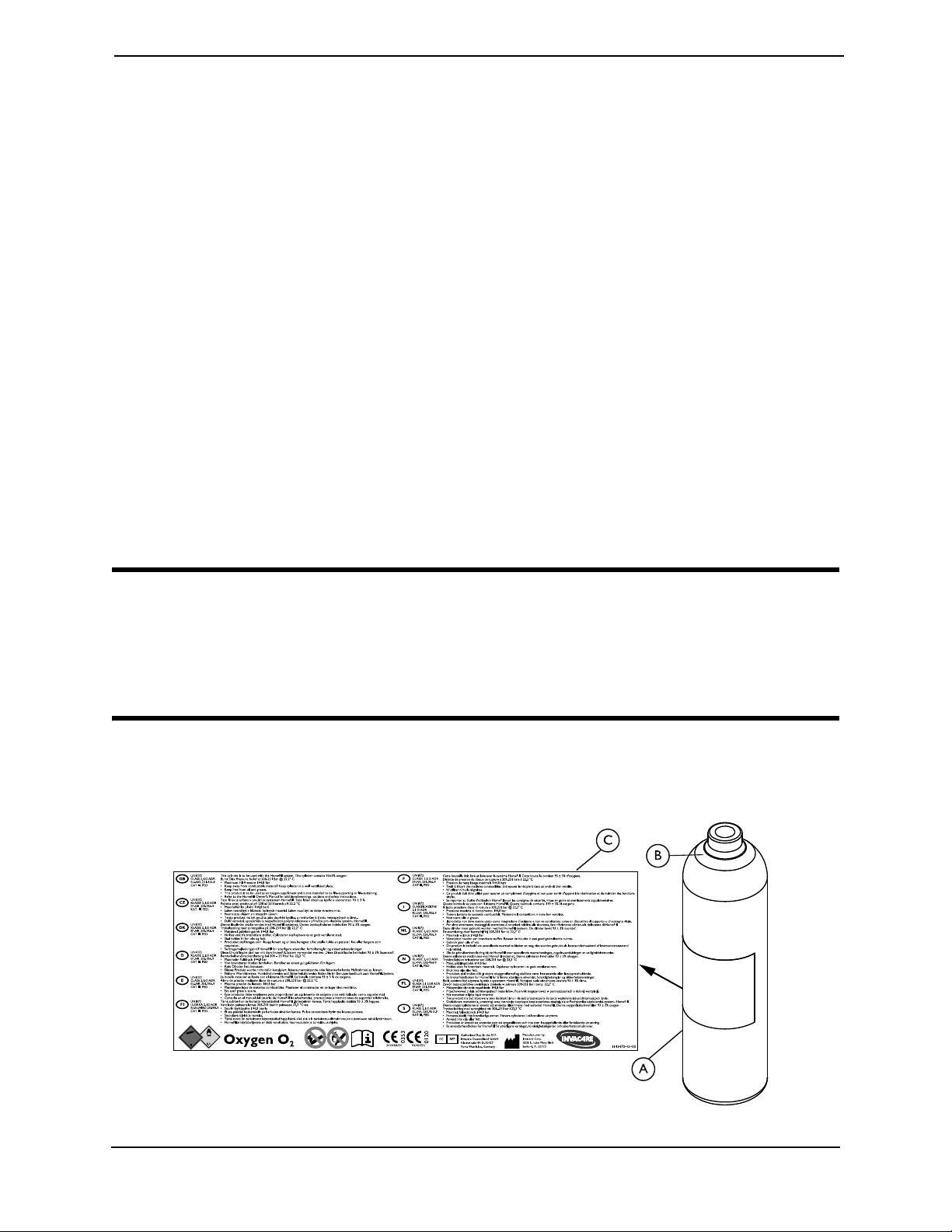
P/N 1145730-D-02
NOTE: Compressor
shown without
cylinder attached.
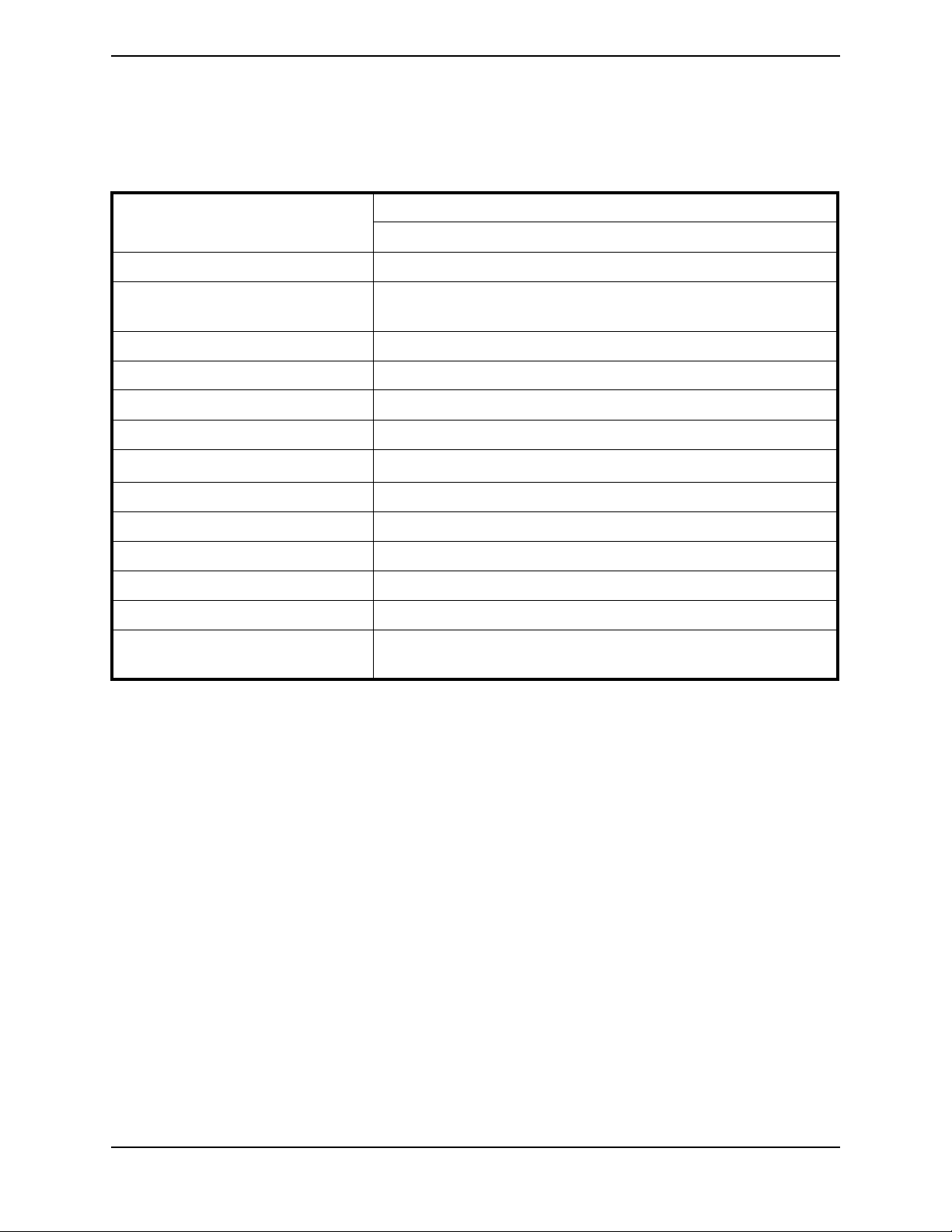
FRONT PANEL LABEL
A PART NUMBER
COMPOSITE LABEL B
PART NUMBER
LANGUAGE
1145730 1148080 English
1145734 1148081 Spanish
1145735 1148082 French
1145736 1148083 German
1145737 1148084 Portuguese
1145738 1148085 Norwegian
1145739 1148086 Finnish
1145740 1148087 Danish
1145741 1148088 Italian
1145742 1148089 Polish
1145743 1148090 Czech
1145744 1148091 Greek
1145745 1148092 Dutch
1145746 1148093 Swedish
1155844 1155847 Chinese
1163176 1163177 Estonian
1164884 1164885 Latvian
1167490 1167489 Lithuanian
A
B
LABEL LOCATIONS
LABEL LOCATIONS
HomeFill® II AW Compressor 8 Part No 1154316
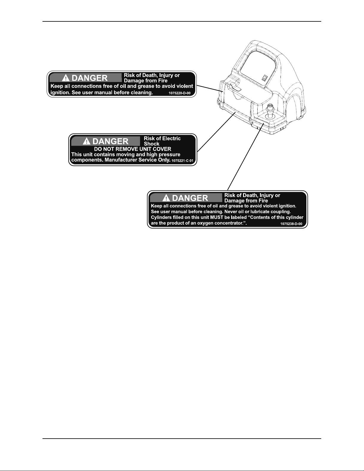
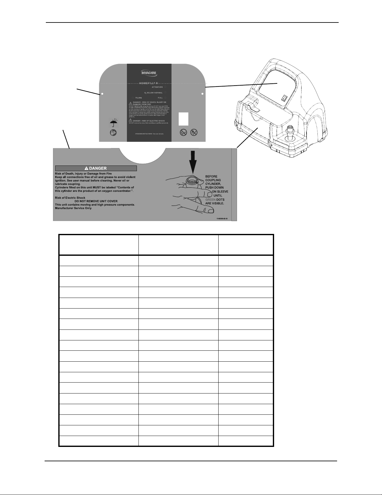
LABEL LOCATIONS
NOTE: Compressor shown without cylinder attached.
Part No 1154316 9 HomeFill® II AW Compressor
GENERAL
GENERAL
Symbols
Symbols in the Manual
Signal words are used in this manual and apply to hazards or unsafe practices which
could result in personal injury or property damage. Refer to the table below for
definitions of the signal words.
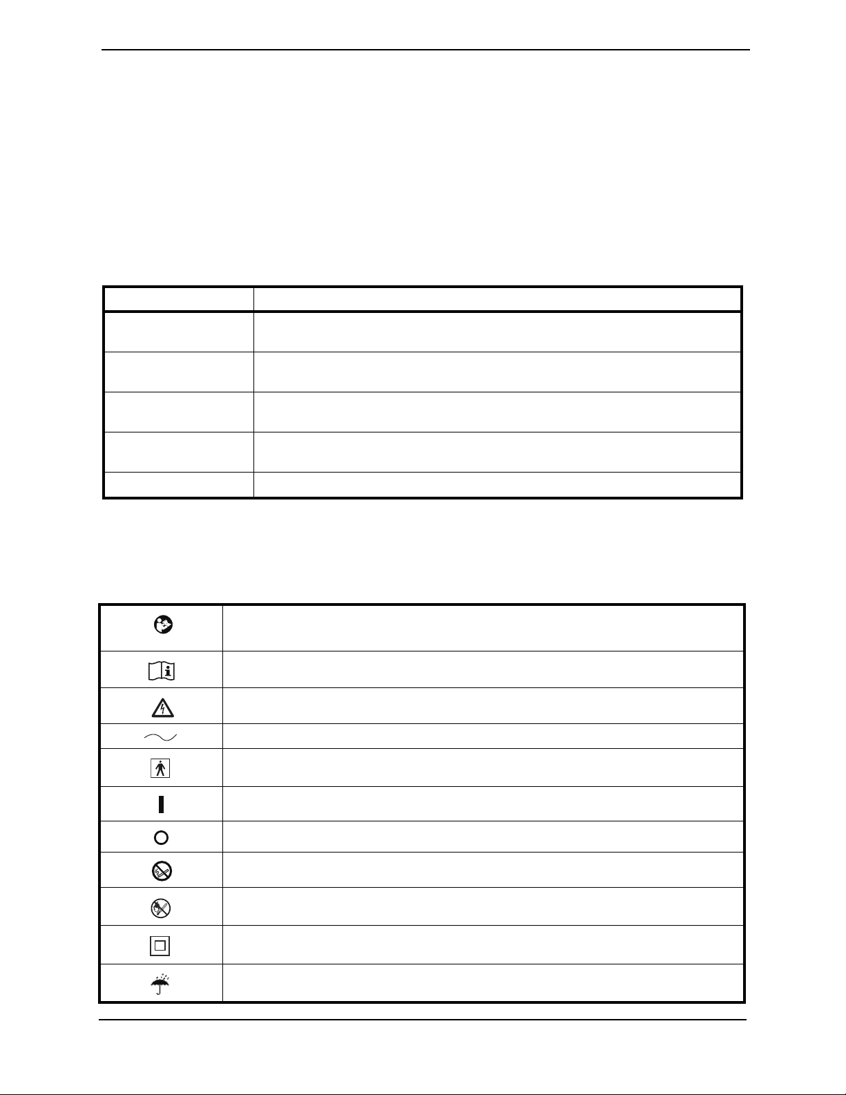
Signal Word Meaning
DANGER
WARNING
CAUTION
! IMPORTANT Indicates a hazardous situation that could result in damage to property if it is not
NOTE:
Danger indicates an imminently hazardous situation which, if not avoided, will result
in death or serious injury.
Warning indicates a potentially hazardous situation which, if not avoided, could result
in death or serious injury.
Caution indicates a potentially hazardous situation which, if not avoided, may result in
property damage or minor injury or both.
avoided.
Gives useful tips, recommendations and information for efficient, trouble-free use.
Symbols on the Product
The following symbols are found on the compressor, compressor packaging or the
oxygen cylinder.
Read the Manual (Compressor)
NOTE: The color of the symbol background is blue on product labels.
Read the Manual (Cylinder)
Electrical Hazard
Alternating Current
Type BF equipment - Applied Parts
Power switch “ON”
Power switch “OFF”
DO NOT smoke
No Open Flame
Class II, Double Insulation. Refer to Double Insulated Products in the Safety section of the manual.
Keep dry in transport or storage and during use
HomeFill® II AW Compressor 10 Part No 1154316

GENERAL
Fuse
Oxidizer
NOTE: The color of the symbol background is yellow on product labels.
Non-flammable gas, class 2 type (oxygen)
NOTE: The color of the symbol background is green on product labels.
Transport and Storage Temperature
Transport and Storage Humidity
Recycle this product. Refer to Disposal of Equipment and Accessories in the After Use section of the
manual.
This product complies with Directive 93/42/EEC concerning medical devices.
The launch date of this product is stated in the CE declaration of conformity.
European Representative
Manufacturer
Intended Use
WARNING
- The use of this device is limited to refilling a specific patient’s own oxygen cylinders.
The designated cylinders MUST be used ONLY by the specific oxygen patient and
are not to be distributed to any other individual for any purpose.
- No other use of this device is indicated.
WARNING
Risk of Death, Injury or Damage
The Invacare HomeFill compressor was designed to be used only with Invacare
oxygen concentrators. Use with other types of devices may cause injury, death or
property damage.
- DO NOT use the Invacare HomeFill compressor with anything other than an
Invacare oxygen concentrator.
- Use only with specially designed Invacare oxygen concentrators that are HomeFill
compatible.
Part No 1154316 11 HomeFill® II AW Compressor
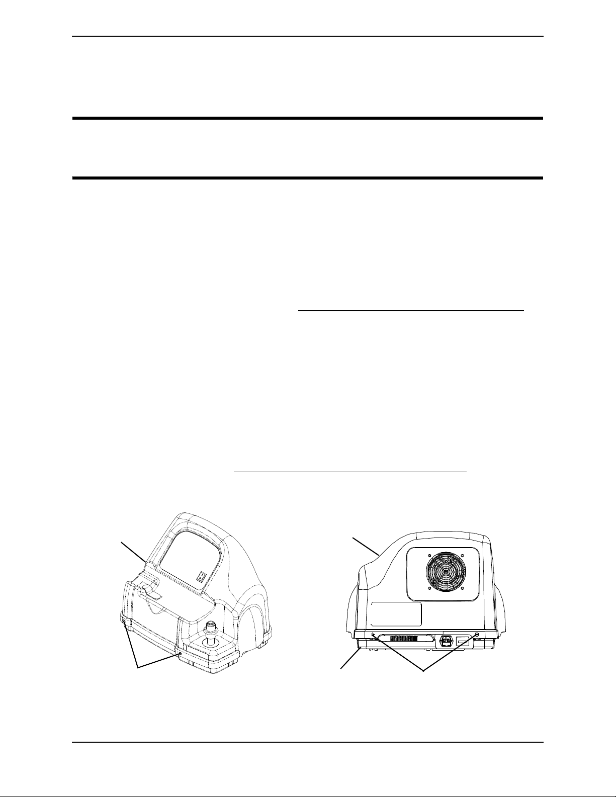
GENERAL
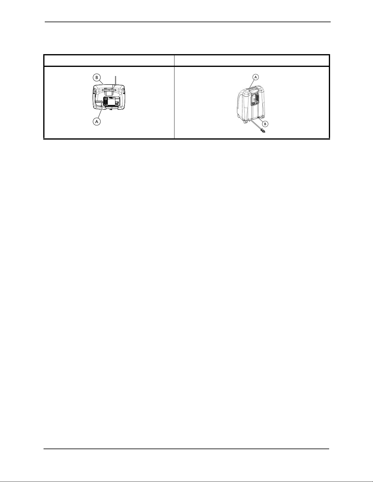
To determine if your oxygen concentrator is HomeFill compatible, examine the lower
right corner of the rear of the oxygen concentrator A for an outlet fitting B.
Platinum - Top View Perfecto2 - Rear View
The intended use of an Invacare HomeFill compressor is an accessory device to an
Invacare oxygen concentrator that enables the patient to refill custom portable oxygen
cylinders for personal use.
This product is intended for single patient use in the indoor homecare environment only
and is not to be used for bulk cylinder refilling.
No specific product knowledge or training is required, other than what is contained in
this manual, to operate the product.
It is not intended for supplying oxygen therapy during refilling.
This product is intended to be used by or under adult supervision only after reading and
understanding the instructions and warnings of this user manual.
HomeFill® II AW Compressor 12 Part No 1154316

SECTION 1—GENERAL GUIDELINES
SECTION 1—GENERAL GUIDELINES
DANGER
Risk Of Death, Injury Or Damage
Improper use of the product may cause death, injury or damage. This section
contains important information for the safe operation and use of this product.
- In order to ensure the safe installation, assembly and operation of the HomeFill
Compressor these instructions MUST be followed.
CAUTION
Federal (statutory) law restricts this device to sale by or on the order of a medical
practitioner licensed by a governmental agency where he/she practices.
- ONLY a licensed medical practitioner may order the purchase or use of this device.
Operating Information
WARNING
Risk of Injury or Damage
The HomeFill is equipped with a high pressure relief valve to ensure the user’s
safety. When activated, this safety feature will make an extremely loud noise. To
avoid injury or damage:
- If this noise occurs, turn the unit Off. DO NOT use. Service unit before use. Refer
to Replacing Burst Disk Fitting on page 42.
If improperly positioned and secured, the power cord and interconnect hose can
cause injury due to tripping and falling. Product damage may also occur.
- The power cord and interconnect hose MUST be routed and secured properly.
- Avoid positioning power cords across areas of high traffic.
- Before moving or repositioning either the compressor or concentrator, ALWAYS
disconnect the AC power cords and the interconnect hose between the
compressor and concentrator.
Blocking the air flow into and out of the compressor may cause injury or damage.
- NEVER block the air openings of the product or place it on a soft surface, such as a
bed or couch, where the air opening may be blocked.
- Keep the openings free from lint, hair and similar foreign items.
- NEVER drop or insert any object into any opening.
A damaged product may malfunction and cause injury or damage. To avoid injury
or damage:
- DO NOT get the compressor wet.
- If the compressor is not working properly, if it has been dropped or damaged, or
submersed in water, a qualified technician MUST examine and repair the unit
BEFORE it is given to the user.
Part No 1154316 13 HomeFill® II AW Compressor

SECTION 1—GENERAL GUIDELINES
WARNING
Risk of Injury or Damage
- If any leakage of the oxygen cylinder is detected, DO NOT attempt to use the
cylinder. Turn the flow selector knob on the regulator to “Off”. If leakage persists,
place the cylinder outdoors and notify your Home Health Care Provider or Service
Representative of this condition.
Risk of Injury
- ALWAYS keep hands and fingers clear of moving parts to avoid injury.
Handling
WARNING
Risk of Fire
- DO NOT store filled cylinder assemblies near a furnace, hot water tank, in the
trunk of a car or other high temperature area. Storage in areas such as this can
result in bursting of the cylinder assembly or fire.
Risk of Injury or Damage
- NEVER transport a compressor with a cylinder connected to or stored on the
compressor. Otherwise, injury or damage can occur.
CAUTION
Risk of Injury or Damage
To reduce the risk of injury or damage from dropped or impacted cylinder
assemblies:
- Use two hands when handling/transporting oxygen cylinders.
- Only use Invacare Corporation carrying bag.
- DO NOT allow cylinder assemblies to tip or fall. DO NOT drop cylinder assemblies.
- Secure gas cylinders so they cannot fall.
- Ensure cylinder is always in upright position when not connected to the HomeFill
compressor.
- DO NOT allow cylinder to impact inanimate objects.
HomeFill® II AW Compressor 14 Part No 1154316

SECTION 1—GENERAL GUIDELINES
EMC Information
WARNING
Risk of Injury or Damage
To reduce the risk of injury or product damage from interference with wireless
equipment:
- Keep the compressor at least 9.8 ft (3.0 m) away from wireless communication
equipment such as wireless home network devices, mobile phones, cordless phones
and base stations, walkie-talkies, etc.
Medical Electrical Equipment needs to be installed and used according to the EMC
information in this manual.
This equipment has been tested and found to comply with EMC limits specified by IEC/
EN 60601-1-2 for Type BF equipment. These limits are determined to provide reasonable
protection against electromagnetic interference in a typical home healthcare
environment. This equipment is not intended for use in a professional healthcare
environment.
Portable and mobile RF communications equipment can affect the operation of this
equipment. The compressor may be stacked on top on an Invacare HomeFill compatible
oxygen concentrator during setup. The compressor operation should be observed to
verify normal cylinder filling in either situation.
Other devices may experience interference from even the low levels of electromagnetic
emissions permitted by the above standard. To determine if the emissions from the
compressor are causing the interference, turn the compressor Off. If the interference with
the other device operation stops, then the compressor is causing the interference. In such
rare cases, interference may be reduced or corrected by one of the following measures:
• Reposition, relocate, or increase the separation between the devices.
• Connect either line powered device to a different electrical power circuit.
Contact Invacare for any additional EMC information or EMC tables for the device
environment.
Part No 1154316 15 HomeFill® II AW Compressor

SECTION 2—CONCENTRATOR VERIFICATION AND MAINTENANCE
SECTION 2— CONCENTRATOR VERIFICATION
AND MAINTENANCE
Performance Verification
NOTE: A dedicated concentrator should be used to test HomeFill compressors.
NOTE: The test concentrator MUST have its performance verified and documented prior to
testing HomeFill compressors.
NOTE: All performance verification and maintenance performed on the test concentrator MUST
be documented on a log sheet that is attached to the concentrator.
1. Turn On the concentrator and set the flow rate to 5 L/min.
2. Allow the concentrator to warm up for a minimum of 30 minutes.
3. After the 30 minute warm-up, check the oxygen concentration using a calibrated
oxygen analyzer.
NOTE: The oxygen concentration reading MUST be above 90% at 5 L/min.
4. Provided the oxygen concentration is 90% or higher at 5 L/min., record the following
on the repair statement and on the test concentrator maintenance log:
A. Date of the performance test and when any service is performed.
B. Hour meter reading.
C. Oxygen concentration.
D. If service is performed, record all details of repair, including preventative
maintenance.
E. Record all parts replaced, and list all detailed performance results.
NOTE: A new entry MUST be made for each performance test, or when any service type items are
performed.
5. Turn the concentrator flow rate down to 2.5 L/min.
6. Connect the test concentrator to the HomeFill compressor to be tested. Refer to
Connecting the Compressor to the Concentrator on page 17.
7. Test the HomeFill compressor. Refer to Troubleshooting/Cylinder Fill Times on
page 85.
HomeFill® II AW Compressor 16 Part No 1154316
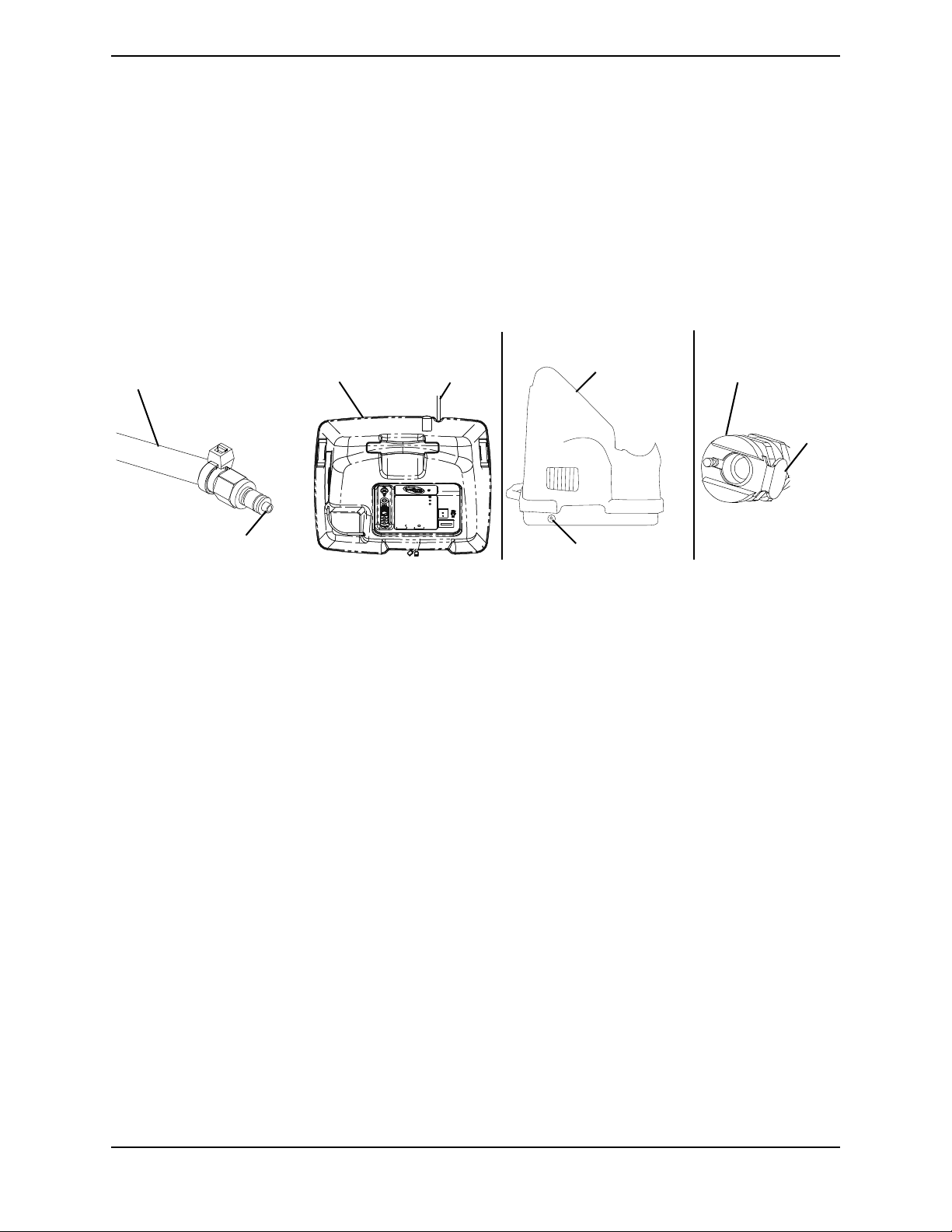
SECTION 2—CONCENTRATOR VERIFICATION AND MAINTENANCE
Insert End of
Interconnect Hose into
Inlet/Outlet Fitting
Inlet/Outlet Fitting
Metal
Tab
Interconnect
Hose (or
Coiled tubing)
Compressor
Inlet Fitting
Power
Cord
Outlet Fitting
CONCENTRATOR
TOP VIEW
DETAIL “A”
DETAIL “C”
DETAIL “B”
Connecting the Compressor to the Concentrator
NOTE: For this procedure, refer to FIGURE 2.1 on page 17.
1. Insert one end of the interconnect hose into the outlet fitting on the back of the
concentrator (Detail “A”).
2. Insert the opposite end of the interconnect hose into the inlet fitting on the side of the
compressor (Detail “B”).
NOTE: The metal tabs on the concentrator outlet fitting and the compressor inlet fitting will pop
out with an audible “click” when the end of the interconnect hose is properly installed (Detail “C”).
3. For models that DO NOT have coiled tubing, loop any excess interconnect hose and
secure to the back of the concentrator with the fastening straps.
FIGURE 2.1 Concentrator Verification and Maintenance
Part No 1154316 17 HomeFill® II AW Compressor
SECTION 3—CHECKLIST AND CYLINDER INSPECTION
SECTION 3—CHECKLIST AND CYLINDER
INSPECTION
Compressor Operation Checklist
Each time the HomeFill Compressor is used to fill a cylinder, complete the following
checklist:
❑ Ensure the concentrator has been on for at least 30 minutes. Refer to the concentrator
User Manual.
❑ Perform the prefill inspection on the cylinder.
❑ Connect the cylinder to the compressor.
❑ Turn the compressor On.
❑ Examine the indicator lights on the control panel.
❑ Disconnect and remove the full cylinder.
❑ Turn the compressor Off.
❑ If filling another cylinder, repeat this checklist.
Cylinder Prefill Inspection
WARNING
Use only cylinders that have the Invacare HomeFill II connection and the HomeFill
II label as shown in FIGURE 3.1 on page 18.
All cylinders MUST be inspected before attempting to fill. Otherwise, injury or
damage may occur.
NOTE: For this procedure, refer to FIGURE 3.1 on page 18.
To identify a HomeFill II compatible cylinder A, look for a black stripe B on the top of the
cylinder and look for the HomeFill II label C.
FIGURE 3.1 Cylinder Prefill Inspection
HomeFill® II AW Compressor 18 Part No 1154316

SECTION 3—CHECKLIST AND CYLINDER INSPECTION
Hydrostatic Testing Date
Aluminum cylinders MUST undergo testing every ten years.
WARNING
Risk of Injury
To reduce the risk of injury:
- DO NOT fill cylinders that have not been tested in the past ten years. Otherwise,
serious personal injury may result. Contact your dealer/Home Care equipment
provider for replacement.
External Examination
1. Examine the outside of the cylinder for the following conditions, and replace the
cylinder if they exist:
• Dents or dings
• Arc burns
• Oil or grease
• Any other signs of damage that might cause a cylinder to be unacceptable or
unsafe for use.
2. Examine the cylinder for evidence of fire or thermal damage. Evidence includes
charring or blistering of the paint, or other protective coating or heat sensitive
indicator. If fire or thermal damage is found, replace the cylinder.
3. Inspect the Invacare valve for the following and replace if found:
• Debris, oil or grease
• Noticeable signs of damage
• Signs of corrosion inside the valve
• Signs of excessive heat or fire damage
Part No 1154316 19 HomeFill® II AW Compressor
SECTION 4—COMPRESSOR OPERATION
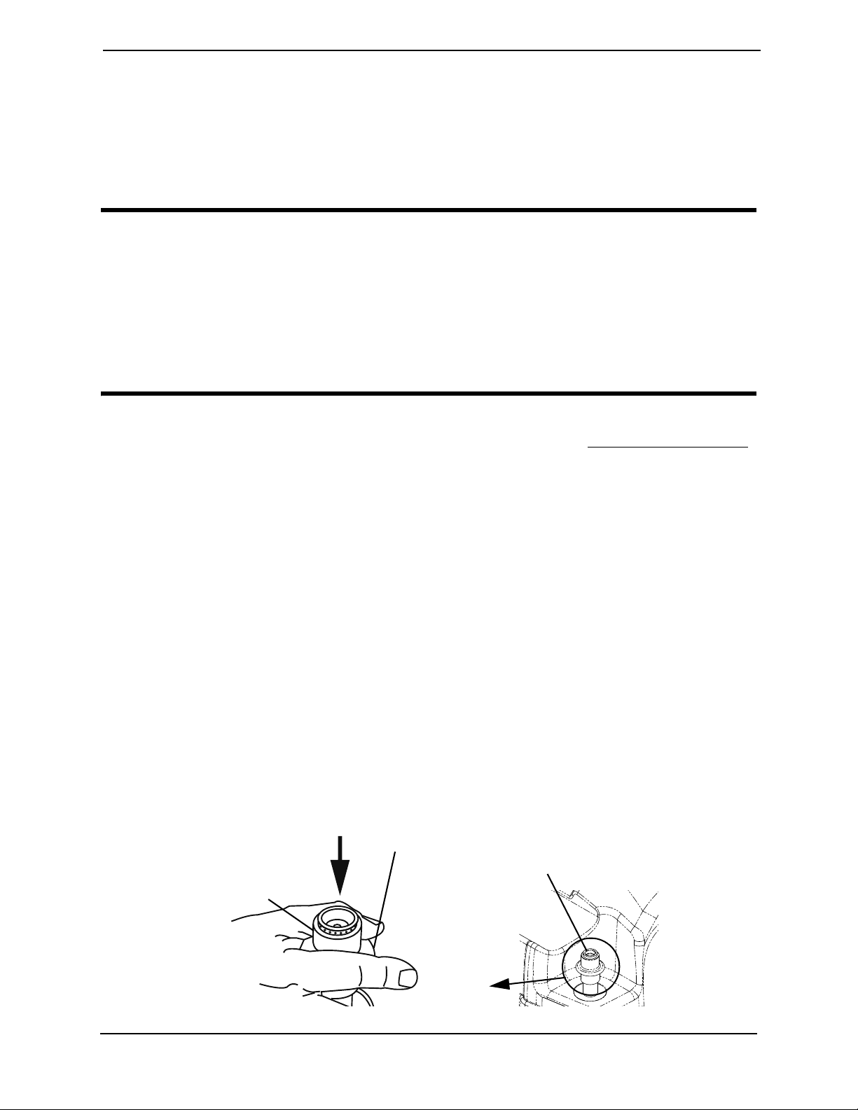
BEFORE
COUPLING
CYLINDER,
PUSH DOWN
ON SLEEVE
UNTIL
GREEN DOTS
Connector Fillport
Outer Ring (Sleeve)
PUSH
DOWN
GREEN Dots
SECTION 4—COMPRESSOR OPERATION
Connecting/Disconnecting Cylinder to/from Compressor
Connecting the Cylinder to the Compressor
WARNING
DO NOT modify any connections on the HomeFill compressor.
NEVER use tools of any kind to connect/disconnect the cylinder and the
compressor. Otherwise, severe injury and/or damage may occur.
DO NOT drop oxygen cylinders. Use two hands when handling/transporting oxygen
cylinders. Otherwise, injury or damage may occur.
DO NOT use a liquid leak detector to test for leaks.
NOTE: For this procedure, refer to FIGURE 4.1 on page 20 and FIGURE 4.2 on page 21.
1. Prior to each use, inspect product for visible damage. Refer to External Examination
on page 19. DO NOT use if any damage is found.
NOTE: If for any reason, any label becomes illegible or lost, contact your dealer/Home Care
equipment provider.
2. Examine the cylinder gauge. If the cylinder pressure is less than 1500 psig. (10342 kPa),
proceed to STEP 2.
NOTE: For location of the cylinder gauge, refer to the cylinder user manual. If the cylinder
pressure is greater than 1500 psig (10342 kPa), DO NOT attempt to top off the cylinder. It may
not fill. Bleed the cylinder or select another cylinder.
3. Set the regulator flow dial on the cylinder to Off (Detail “B” of FIGURE 4.2). Refer to
the cylinder user manual.
4. Remove the cylinder and connector fillport covers (if present).
NOTE: On older models, the green dots do not exist.
5. To reset the connector, momentarily push down on the outer ring (sleeve) of the
connector fillport until GREEN dots are visible (FIGURE 4.1).
NOTE: If the outer ring (sleeve) is in the up position (GREEN dots not visible), the connector
fillport will not be able to accept the cylinder fillport. Pushing down momentarily will reset the
connector fillport (GREEN dots visible) to accept the cylinder fillport.
HomeFill® II AW Compressor 20 Part No 1154316
FIGURE 4.1 Resetting Connector Fillport
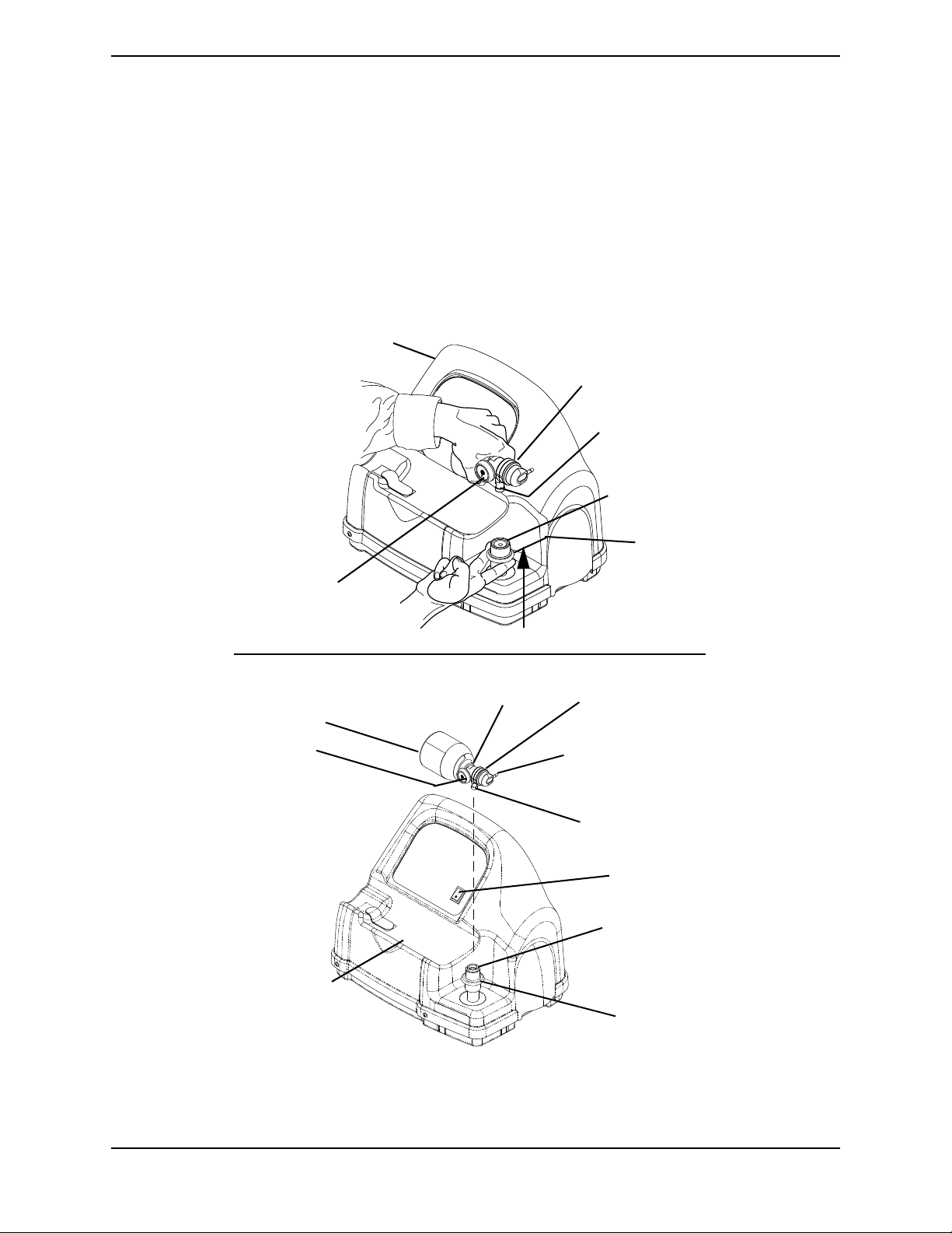
SECTION 4—COMPRESSOR OPERATION
Cylinder/Regulator
Assembly
Compressor
Cylinder
Gauge
Cylinder
Fillport
Connector
Fillport
PULL UP
Cylinder
Compressor
Cradle
Cylinder
Gauge
Regulator
Flow Dial
Cylinder Fillport
Outer Ring
(Sleeve)
Connector
Fillport
NOTE: Fillport covers not shown for clarity.
Outlet (Cannula)
Connection
Power
Switch
Regulator
Outer Ring
(Sleeve)
DETAIL “A”
DETAIL “B”
6. Grasp the cylinder/regulator assembly in the area behind the cylinder gauge in
FIGURE 4.2 on page 21.
7. Position the cylinder in the compressor cradle (Detail “A” of FIGURE 4.2).
8. Align the cylinder fillport with the connector fillport (Detail “B” of FIGURE 4.2).
9. Pull up on the outer ring (sleeve) of the connector fillport while pushing down on the
cylinder/regulator assembly to couple the cylinder fillport into the connector fillport
(Detail “A” of FIGURE 4.2).
NOTE: The cylinder is properly connected when an audible “click” is heard.
FIGURE 4.2 Connecting the Cylinder to the Compressor
Part No 1154316 21 HomeFill® II AW Compressor
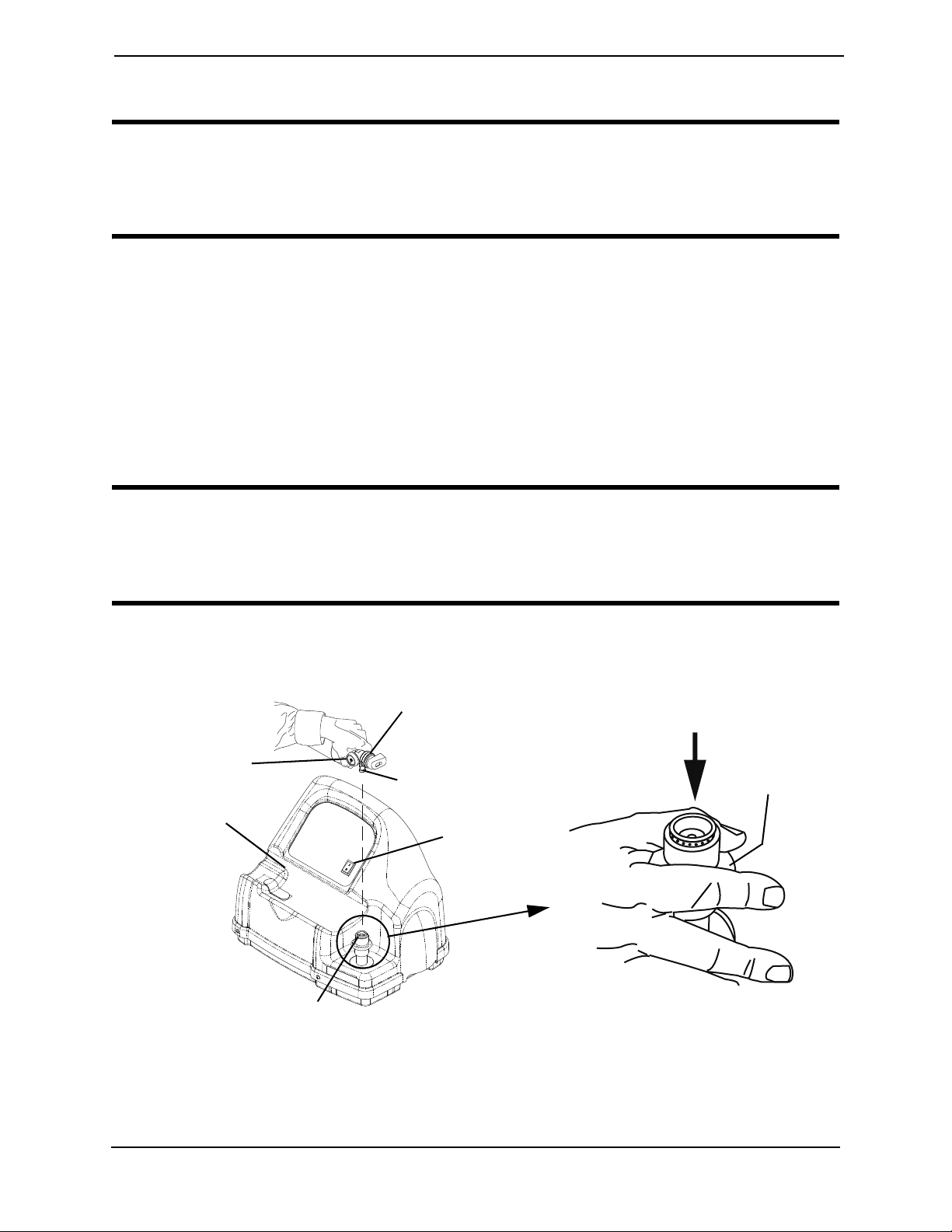
SECTION 4—COMPRESSOR OPERATION
Cylinder/Regulator
Assembly
Compressor
Cradle
Cylinder Gauge
Cylinder
Fillport
Connector Fillport
Outer Ring
(Sleeve)
PUSH DOWN
Power Switch
Disconnecting Cylinder From Compressor
WARNING
DO NOT modify any connections on the HomeFill compressor. NEVER use tools of
any kind to connect/disconnect the cylinder and the compressor. Otherwise, severe
injury and/or damage may occur.
NOTE: For this procedure, refer to FIGURE 4.3 on page 22.
1. Press the compressor power switch to the Off (O) position.
2. Grasp the cylinder/regulator assembly in the area behind the cylinder gauge.
3. With the other hand, grasp the outer ring (sleeve) of the connector fillport and push
down.
4. Lift up on the cylinder/regulator assembly to remove from the connector fillport.
5. When the cylinder fillport is disconnected from the connector fillport, release the
outer ring (sleeve) of the connector fillport and use two hands to remove the cylinder
from the compressor cradle.
WARNING
- The fillport cover on the connector fillport and the cylinder fillport MUST be
replaced after filling and whenever not in use. If either of the fillport covers are
missing replace these parts before using or returning to the user.
6. Place the fillport covers onto the connector and cylinder fillports.
NOTE: The fillport covers should be used whenever cylinders are not being filled.
FIGURE 4.3 Disconnecting Cylinder From Compressor
HomeFill® II AW Compressor 22 Part No 1154316

SECTION 4—COMPRESSOR OPERATION
Turning the Compressor On and Off
NOTE: For this procedure, refer to FIGURE 4.4 on page 24.
1. Make sure the concentrator is On and runs a minimum of 30 minutes.
CAUTION
The concentrator flow rate to the patient MUST be set at maximum: 2.5 L/min. or
less for Platinum 5, Platinum S, Perfecto2 and 5 L/min. for Platinum 9. Otherwise,
the oxygen level to the compressor will be <90% and the compressor will not fill the
cylinder.
2. Set the concentrator flow rate to the patient to 2.5 L/min. or less for Platinum 5,
Platinum S, Perfecto2 and 5 L/min. for Platinum 9.
3. Make sure the cylinder is connected to the compressor. Refer to Connecting the
Cylinder to the Compressor on page 20.
4. Push the power switch on the control panel to the On position.
5. Perform one of the following:
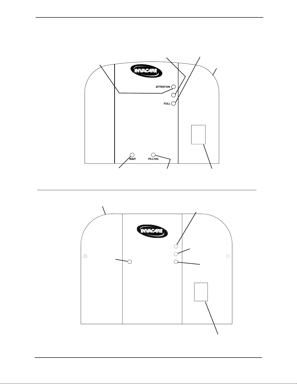
A. For HomeFill units manufactured before 02/02/06 - Examine the control panel. The
following sequence of events should occur:
• 0-3 minutes - The WAIT (YELLOW) light will be lit while the compressor
warms up.
•After three minutes - The FILLING (GREEN) light will be on while the cylinder
is filling.
•The FULL (GREEN) light will be on when the cylinder is finished filling. Proceed
to STEP 6.
B. For HomeFill units manufactured after 02/02/06 - Examine the control panel. The
following sequence of events should occur:
• 0-3 minutes - The O
Below Normal (YELLOW) light will be lit while the
2
compressor warms up.
• After three minutes - The FILLING (GREEN) light will be on while the cylinder
is filling.
• The FULL (GREEN) light will be on when the cylinder is finished filling.
Proceed to STEP 6.
NOTE: The O
BELOW NORMAL (YELLOW) light may come on if the oxygen level from the
2
concentrator has not yet reached or drops below 90%. The compressor will begin or resume filling
when the oxygen level reaches 90%. If light does not go Off within 10 minutes, refer to
Troubleshooting on page 85.
NOTE: If the ATTENTION (RED) light and audible alarm are on, refer to Troubleshooting
on
page 85.
6. Remove the full cylinder. Refer to Disconnecting Cylinder From Compressor on
page 22.
Part No 1154316 23 HomeFill® II AW Compressor
SECTION 4—COMPRESSOR OPERATION
USE NO OIL
I
O
O2 BELOW NORMAL
ATTENTION
(RED Light and
Audible Alarm)
O
2
BELOW
NORMAL
(YELLOW Light)
FULL
(GREEN Light)
Control
Panel
WAIT
(YELLOW Light)
FILLING
(GREEN Light)
Power Switch
For HomeFill units manufactured before 02/02/06
I
O
Attention (RED light and
Audible Alarm)
O
2
below normal
(YELLOW light)
Full
(GREEN Light)
Control Panel
Power Switch
Filling
(GREEN
Light)
ATTENTION
O2 BELOW NORMAL
FULL
FILLING
For HomeFill units manufactured after 02/02/06
FIGURE 4.4 Turning the Compressor On and Off
HomeFill® II AW Compressor 24 Part No 1154316
SECTION 5—CABINET ASSEMBLY
Mounting Screws
Cabinet
REAR VIEW
Mounting Screws
Base Assembly
Cabinet
SECTION 5—CABINET ASSEMBLY
Removing/Installing the Cabinet
DANGER
To prevent electrical shock, ALWAYS disconnect HomeFill from electrical outlet
before servicing.
NOTE: For this procedure, refer to FIGURE 5.1.
Tools required for this procedure are:
• Phillips screwdriver
Removing
1. Unplug the power cord from the electrical outlet.
2. Remove cylinder (if attached). Refer to Disconnecting Cylinder From Compressor on
page 22.
3. Remove the four mounting screws that secure the cabinet assembly to the base
assembly.
4. Lift the cabinet straight up off of the base assembly.
Installing
1. Position the cabinet on the base assembly as shown.
2. Secure the cabinet to the base assembly with four mounting screws. Securely tighten.
3. Reattach cylinder. Refer to Connecting the Cylinder to the Compressor on page 20.
4. Plug power cord into electrical outlet.
FIGURE 5.1 Removing/Installing the Cabinet
Part No 1154316 25 HomeFill® II AW Compressor
SECTION 5—CABINET ASSEMBLY
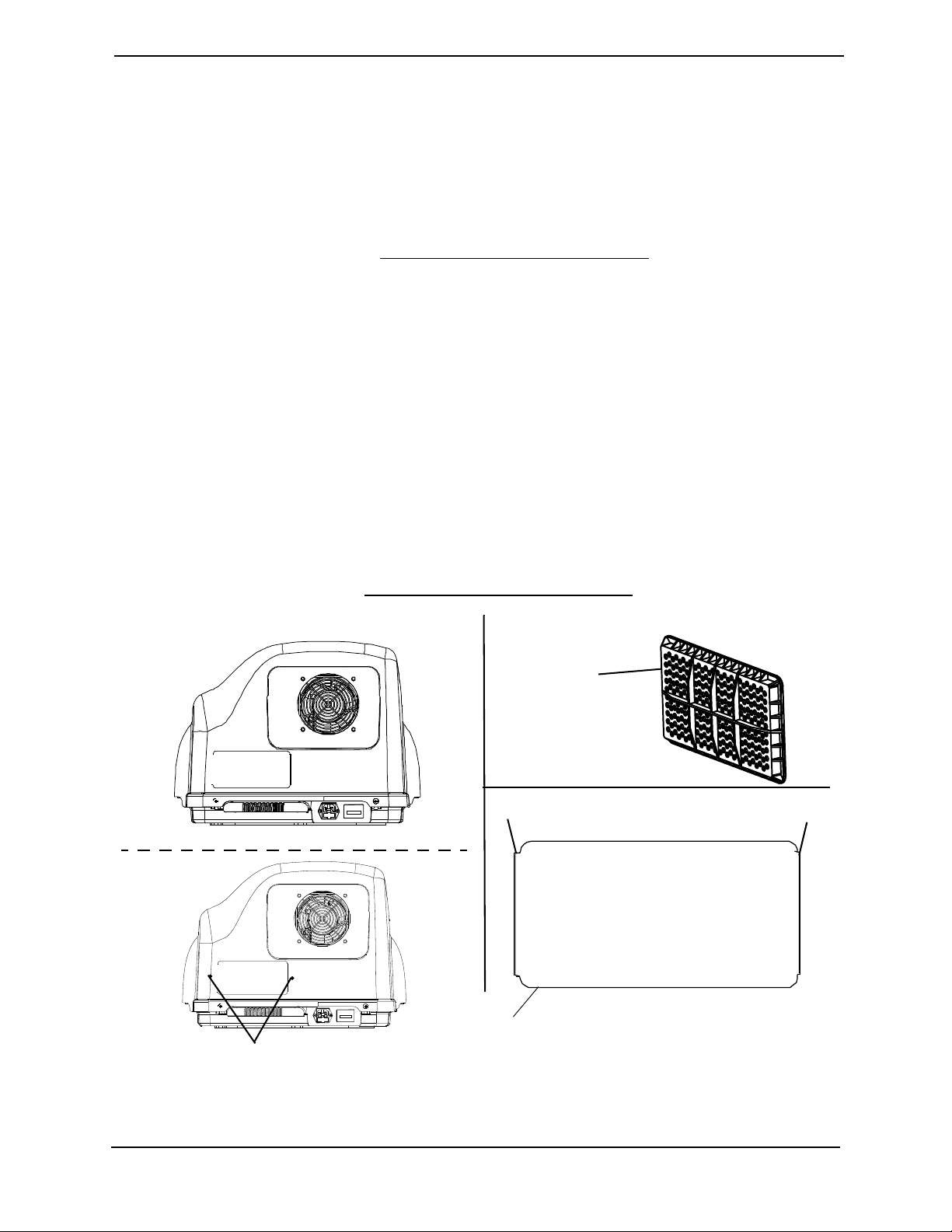
DETAIL “A”
DETAIL “B”
Cabinet Filter
Grid
DETAIL “C”
NOTE: Lip of the filter grid MUST
be on the outside of the cabinet to
secure the filter grid in place.
Lip
Lip
Plastic Rivets
Filter Grid
Removing/Installing the Cabinet Filter Grid
NOTE: For this procedure, refer to FIGURE 5.2.
Tools required: Flat head screwdriver and .09 mm drill bit
Removing
1. Remove the cabinet. Refer to Removing/Installing the Cabinet on page 25.
2. Perform one of the following:
• For units that have plastic rivets, remove the plastic rivets by pushing the rivets
from the inside out with a .09 mm drill bit, proceed to STEP 3.
• For units without plastic rivets, proceed to STEP 3.
3. Using the flat head screwdriver, pry the lip of the cabinet filter grid out of the cabinet
(Detail “C”).
Installing
NOTE: For units that have plastic rivets, the cabinet MUST be replaced to use the new filter grid.
1. Install the cabinet filter grid (Detail “B”) to the inside of the cabinet. Ensure that the
lip of the cabinet filter grid is on the outside of the cabinet.
2. Install the cabinet. Refer to Removing/Installing the Cabinet on page 25.
FIGURE 5.2 Removing/Installing the Cabinet Filter Grid
HomeFill® II AW Compressor 26 Part No 1154316
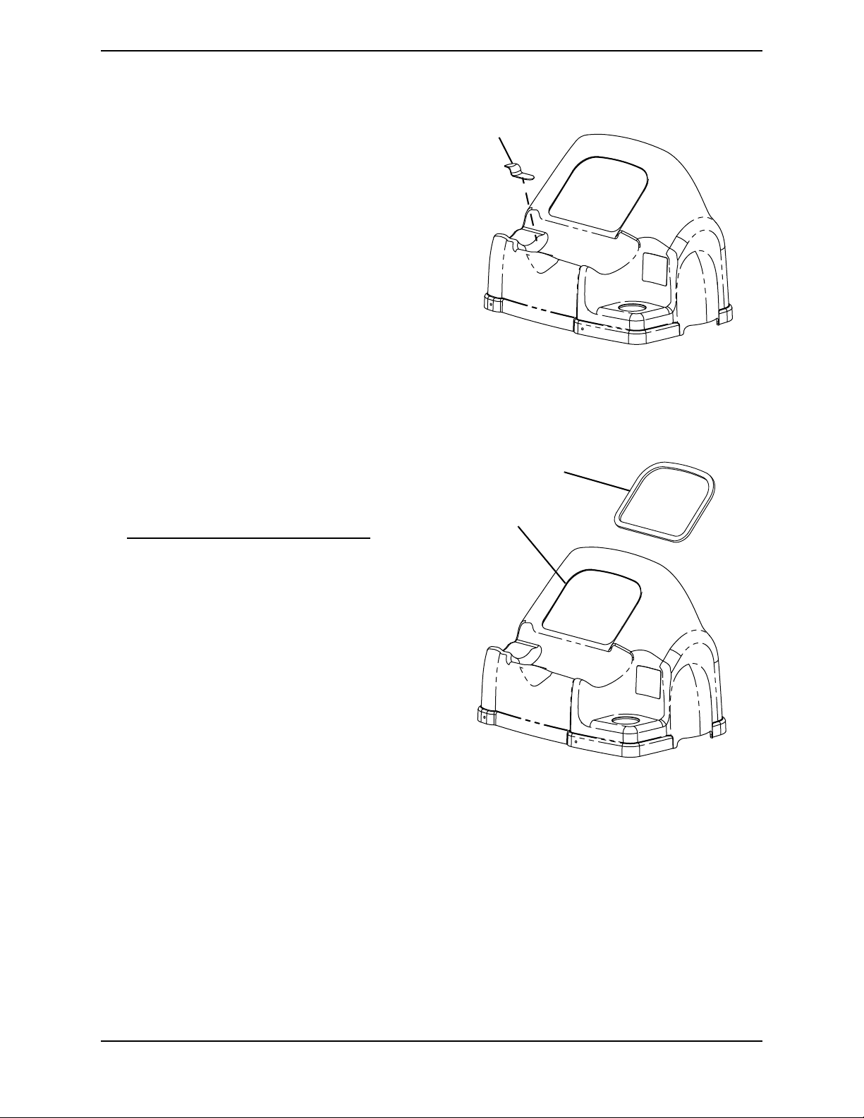
SECTION 5—CABINET ASSEMBLY
Pad
Control Panel
Opening
Foam Gasket
Replacing Non-Skid Adhesive Back Pad
NOTE: For this procedure, refer to
FIGURE 5.3.
1. Peel the existing pad from the cabinet
and discard.
2. Peel the backing from the new pad.
3. Attach the new pad to the cabinet.
FIGURE 5.3 Replacing Non-Skid Adhesive
Replacing Foam Gasket
Back Pad
NOTE: For this procedure, refer to
FIGURE 5.4.
1. Remove the cabinet. Refer to
Removing/Installing the Cabinet on
page 25.
2. Peel the existing foam gasket from the
inside of the control panel opening and
discard.
3. Peel the backing from the new foam
gasket.
4. Attach the new foam gasket to the
inside of control panel opening.
FIGURE 5.4 Replacing Foam Gasket
Part No 1154316 27 HomeFill® II AW Compressor
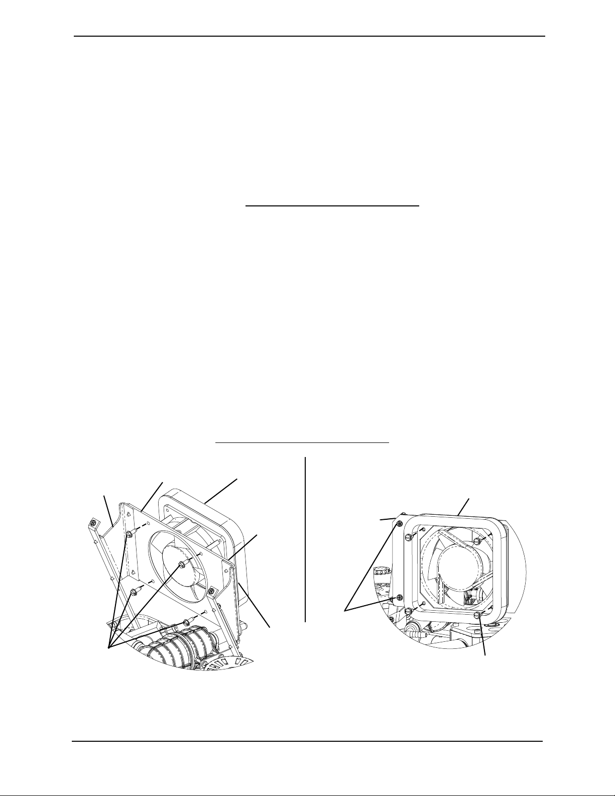
SECTION 6—PANEL ASSEMBLY
Mounting Screw
Fan Inlet Seal
DETAIL “A”
DETAIL “B”
Mounting
Screws
Isolator Plate
Fan Mounting
Bracket
Mounting
Screws
Isolator Plate
Wire
Connectors
(Not shown)
Exhaust Fan
Airflow
Arrow points
to back of
unit
SECTION 6—PANEL ASSEMBLY
Replacing Exhaust Fan
NOTE: For this procedure, refer to FIGURE 6.1.
Tools required for this procedure are:
• Phillips screwdriver
• Torque Wrench
1. Remove the cabinet. Refer to Removing/Installing the Cabinet on page 25.
2. Note the wire orientation of the two wires located on the exhaust fan.
3. Disconnect the two wires from exhaust fan wire connectors.
4. Remove the four mounting screws securing the fan inlet seal to the exhaust fan (Detail
“B”).
5. Set the fan inlet seal aside for re-use.
6. Remove the four mounting screws securing the exhaust fan to the isolator plate.
NOTE: Before securing exhaust fan in place, ensure airflow arrow (molded into the side of the fan)
points toward the back and out of the unit.
7. Secure the exhaust fan to the isolator plate with four mounting screws. The mounting
screws MUST be torqued to 20–30 in-lbs (2.26-3.39 Nm).
8. Secure the fan inlet seal to the exhaust fan with four mounting screws. The mounting
screws MUST be torqued to 20–30 in-lbs (2.26-3.39 Nm).
9. Connect the two wires to the exhaust fan in the orientation previously noted.
10. Install cabinet. Refer to Removing/Installing the Cabinet
on page 25.
FIGURE 6.1 Replacing Exhaust Fan
HomeFill® II AW Compressor 28 Part No 1154316

Removing/Installing Control Panel
NOTE: For this procedure, refer to FIGURE 6.2.
Tools required for this procedure are:
• Phillips screwdriver
SECTION 6—PANEL ASSEMBLY
1. Remove the cabinet. Refer to Removing/Installing the Cabinet
2. Remove the two mounting screws securing the top of the control panel (Detail “A”).
3. Loosen the two mounting screws securing the bottom of the control panel (Detail “A”).
4. Slowly pull the control panel back to expose the circuit board and its connections.
5. Disconnect the three wiring harnesses from the three connectors on the circuit board
(Detail “B”).
on page 25.
CAUTION
DO NOT disconnect the opaque oxygen sensor tube from the sensor as this may
damage the circuit board.
6. Disconnect the opaque oxygen sensor tube from the barbed fitting opposite the sensor
(Detail “B”).
7. Note the location of the two wire connectors of the power switch for later replacement.
8. Disconnect the two wire connectors from the power switch (Detail “B”).
9. Disconnect bleed resistor from the control panel (Detail “C”).
10. Remove the control panel.
Installing
1. Connect bleed resistor to the control panel (Detail “C”).
2. Connect the two wire connectors to the power switch (Detail “B”) in the orientation
noted previously.
3. Connect the opaque oxygen sensor tube to the barbed fitting on the opposite end of
the sensor (Detail “B”).
4. Connect the three wiring harnesses to the three connectors on the circuit board (Detail
“B”).
5. Secure the bottom of the control panel with two mounting screws. Securely tighten.
6. Secure the top of the control panel with two mounting screws. Securely tighten.
7. Install the cabinet. Refer to Removing/Installing the Cabinet on page 25.
Part No 1154316 29 HomeFill® II AW Compressor
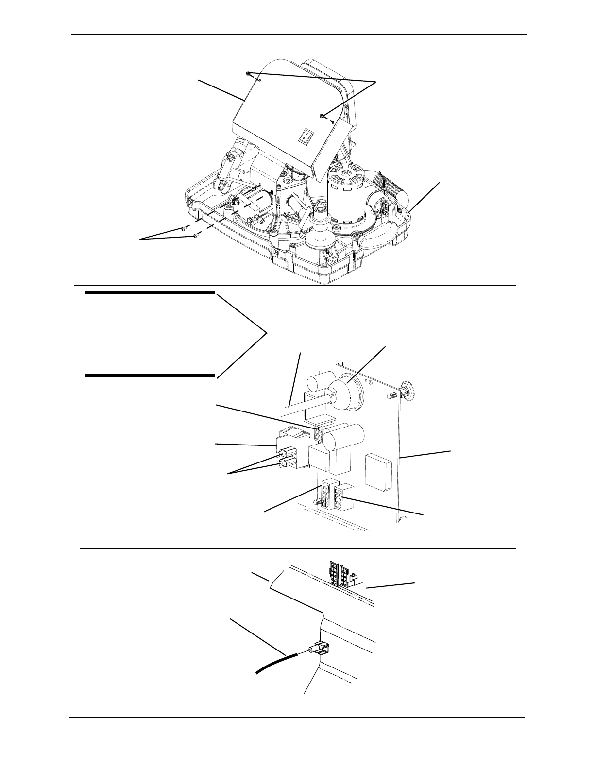
Mounting
Screws
Mounting
Screws
Control Panel
Base Assembly
Opaque Oxygen
Sensor Tube
Sensor
Wiring Harness
Connection
Wiring Harness
Connection
Wiring Harness
Connection
Circuit
Board
Wire Connectors
Power Switch
Bleed Resistor
Assembly 2
Control Panel
DETAIL “A”
CAUTION
DO NOT disconnect
the opaque oxygen
sensor tube from the
sensor.
Partial View of
Circuit Board
SECTION 6—PANEL ASSEMBLY
FIGURE 6.2 Removing/Installing Control Panel
HomeFill® II AW Compressor 30 Part No 1154316
 Loading...