

Invacare HomeFill II Service Manual

Service Manual
HomeFill™II Compressor
NOTE: Compressor shown without cylinder attached.
NOT FOR GENERAL DISTRIBUTION - DO NOT COPY
DEALER: Keep this manual. The
procedures in this manual MUST be
performed by a qualified technician.
For more information regarding
Invacare products, parts, and services,
please visit www.invacare.com

REFERENCE DOCUMENTS
WARNING
THE PROCEDURES IN THIS SERVICE MANUAL MUST BE PERFORMED BY A QUALIFIED TECHNICIAN.
DO NOT SERVICE OR OPERATE THIS EQUIPMENT WITHOUT
FIRST READING AND UNDERSTANDING (1) THE OWNER’S
OPERATOR AND MAINTENANCE MANUAL AND (2) THE SERVICE
MANUAL. IF YOU ARE UNABLE TO UNDERSTAND THE
WARNINGS, CAUTIONS AND INSTRUCTIONS, CONTACT
INVACARE TECHNICAL SUPPORT BEFORE ATTEMPTING TO
SERVICE OR OPERATE THIS EQUIPMENT - OTHERWISE, INJURY
OR DAMAGE MAY RESULT.
REFERENCE DOCUMENTS
Refer to the following table for part numbers of additional documents which are referenced in this manual.
MANUAL PART NUMBER
HomeFill II Compressor Operator’s Manual 1100873
Platinum Concentrator Owner’s Manual 1118353
Platinum Concentrator Service Manual 1110538
NOTE: Updated versions of this manual are available on www.invacare.com.
HomeFill™II Compressor 2 Part No 1141487

TABLE OF CONTENTS
TABLE OF CONTENTS
REFERENCE DOCUMENTS ................................................................. 2
SPECIAL NOTES ................................................................................ 6
TYPICAL PRODUCT PARAMETERS .................................................... 7
LABEL LOCATION ............................................................................ 8
SECTION 1—GENERAL GUIDELINES ................................................... 9
Operating Information...............................................................................................................................9
Handling ......................................................................................................................................................10
Maintenance...............................................................................................................................................10
Radio Frequency Interference ...............................................................................................................10
To Reduce the Risk of Burns, Electrocution, Fire or Injury to Persons......................................10
SECTION 2— CONCENTRATOR VERIFICATION AND
MAINTENANCE ............................................................................. 12
Performance Verification........................................................................................................................12
Connecting the Compressor to the Concentrator..........................................................................12
SECTION 3—CHECKLIST AND CYLINDER INSPECTION ..................... 14
Compressor Operation Checklist........................................................................................................14
Cylinder Prefill Inspection ......................................................................................................................14
Hydrostatic Testing Date...................................................................................................................14
External Examination ..........................................................................................................................15
SECTION 4—COMPRESSOR OPERATION .......................................... 16
Connecting/Disconnecting Cylinder to/from Compressor............................................................16
Connecting the Cylinder to the Compressor...............................................................................16
Disconnecting Cylinder From Compressor ..................................................................................18
Turning the Compressor On.................................................................................................................19
SECTION 5—CABINET ASSEMBLY .................................................... 21
Removing/Installing the Cabinet............................................................................................................21
Removing ...............................................................................................................................................21
Installing..................................................................................................................................................21
Removing/Installing the Cabinet Filter Grid .......................................................................................22
Removing ...............................................................................................................................................22
Installing..................................................................................................................................................22
Replacing Non-Skid Adhesive Back Pad ..............................................................................................23
Replacing Foam Gasket ...........................................................................................................................23
Part No 1141487 3 HomeFill™II Compressor

TABLE OF CONTENTS
TABLE OF CONTENTS
SECTION 6—PANEL ASSEMBLY ....................................................... 24
Replacing Exhaust Fan..............................................................................................................................24
Removing/Installing Control Panel........................................................................................................25
Installing ......................................................................................................................................................25
Testing/Replacing the Power Switch....................................................................................................27
Replacing Circuit Board ..........................................................................................................................28
Replacing/Rebuilding Compressor Assembly.....................................................................................29
Replacing Accumulator Assembly.........................................................................................................29
Units manufactured before 10/03/05 ..............................................................................................29
Units manufactured after 10/02/05..................................................................................................30
Installing Accumulator Assembly......................................................................................................30
SECTION 7—BASE COMPONENTS .................................................... 32
Replacing Fuse ...........................................................................................................................................32
Removing/Installing the Power Inlet.....................................................................................................33
Removing ...............................................................................................................................................33
Installing..................................................................................................................................................33
Replacing Hour Meter.............................................................................................................................34
Replacing O2 Inlet Connector/Inlet Connector Dust Cap.............................................................34
Replacing Transformer............................................................................................................................35
Testing/Replacing Capacitor...................................................................................................................36
Testing ....................................................................................................................................................36
Replacing Capacitor.............................................................................................................................37
Removing Connector Fillport Dust Cover and Lanyard - Units Manufactured
Before 10/03/2005....................................................................................................................................38
Removing ...............................................................................................................................................38
Removing/Installing Connector Fillport Dust Cover and Lanyard - Units Manufactured
After 10/02/2005 ......................................................................................................................................39
High Pressure Switch Replacement......................................................................................................40
Replacing Burst Disk Fitting ...................................................................................................................41
SECTION 8—WIRING ASSEMBLIES .................................................... 43
Replacing Wiring Assemblies.................................................................................................................43
Full View of Wiring Harnesses .........................................................................................................43
Replacing Transformer Assembly.....................................................................................................43
Replacing Bleed Resistor Assemblies ..............................................................................................44
Replacing HFII Assembly Wire Harness.........................................................................................45
HomeFill™II Compressor 4 Part No 1141487

SECTION 9—TROUBLESHOOTING/CYLINDER FILL TIMES ................... 47
Indicator Light Explanation.....................................................................................................................47
Troubleshooting........................................................................................................................................47
Cylinder Fill Times ...................................................................................................................................49
Leak Test ....................................................................................................................................................49
Cylinder Fill Test ......................................................................................................................................50
HomeFill II 2000 psi Switch/P.C.B. Shut Down Test........................................................................53
SECTION 10—MAINTENANCE ......................................................... 55
Cleaning/Replacing the Cabinet Filter..................................................................................................55
Cleaning Cabinet.......................................................................................................................................55
Verification Process - Invacare HomeFill II Compressor................................................................56
Function Test.............................................................................................................................................56
......................................................................................................................................................................57
Verification Process - Invacare HomeFill II Cylinder .......................................................................57
Function Test.............................................................................................................................................58
LIMITED WARRANTY ..................................................................... 59
Part No 1141487 5 HomeFill™II Compressor
SPECIAL NOTES
SPECIAL NOTES
Signal words are used in this manual and apply to hazards or unsafe practices which could result in personal injury or property damage. Refer to the table below for definitions of the signal words.
SIGNAL WORD MEANING
DANGER
WARNING
CAUTION
Danger indicates an imminently hazardous situation which, if not avoided, will result in death or serious injury.
Warning indicates a potentially hazardous situation which, if not avoided, could result in death or serious injury.
Caution indicates a potentially hazardous situation which, if not avoided, may result in property damage.
NOTICE
THE INFORMATION CONTAINED IN THIS DOCUMENT IS SUBJECT TO CHANGE WITHOUT NOTICE.
DANGER
Users MUST not smoke while using this device. Keep all matches, lighted cigarettes
or other sources of ignition out of the room in which this product is located. NO
SMOKING signs should be prominently displayed. Textiles and other materials that
normally would not burn are easily ignited and burn with great intensity in oxygen
enriched air. Failure to observe this warning can result in severe fire, property
damage, and cause physical injury or death.
WARNING
Invacare products are specifically designed and manufactured for use in conjunction with Invacare accessories. Accessories designed by other manufacturers have not been tested by Invacare and are not recommended for use with Invacare products.
HomeFill™II Compressor 6 Part No 1141487

TYPICAL PRODUCT PARAMETERS
TYPICAL PRODUCT PARAMETERS
REGULATORY LISTING: Double Insulated Product
ETL Certified Complying with UL1431, UL1097 (US)
ETL Certified Complying with CAN/CSA C22.2 No. 68 (Canada)
OPERATING TEMPERATURE: 50 to 95° F (10 to 35° C) @ 20 to 60% non-condensing humidity
STORAGE TEMPERATURE: -10 to 150° F (-23 to 65° C) @ 15 to 95% humidity
INPUT PRESSURE REQUIRED: 14 - 21 psi
INPUT FLOW REQUIRED: 2 L/min
INPUT O
WIDTH: 20 ¼ inches
HEIGHT: 15 inches
DEPTH: 16 inches
WEIGHT: 33 lbs
SHIPPING WEIGHT: 39 lbs
% REQUIRED: >90% O
2
2
Part No 1141487 7 HomeFill™II Compressor
LABEL LOCATION
LABEL LOCATION
WARNING
Keep all connections free of oil and grease to avoid violent
ignition. See Owner's Manual before cleaning.
This unit contains moving and high pressure
components. Manufacturer Service Only.
NOTE: Compressor shown without cylinder attached.
!
!
WARNING
DO NOT REMOVE UNIT COVER
Cylinders filled on this unit must be labeled "Contents of
this cylinder are the product of an oxygen concentrator."
P/N 1075220 Rev C - 10/04
P/N 1075221
Rev B - 10/04
!
Keep all connections free of oil and grease.
See Owner's Manual before cleaning.
WARNING
P/N 1075238
Rev B - 10/04
HomeFill™II Compressor 8 Part No 1141487

SECTION 1—GENERAL GUIDELINES
SECTION 1—GENERAL GUIDELINES
WARNING
GENERAL GUIDELINES contains important information for the safe operation and
use of this product. DO NOT use this product or any available optional equipment
without first completely reading and understanding these instructions and any
additional instructional material such as Owner’s Manuals, Service Manuals or
Instruction Sheets supplied with this product or optional equipment. If you are
unable to understand the Warnings, Cautions or Instructions, contact a healthcare
professional, dealer or technical personnel before attempting to use this equipment
- otherwise, injury or damage may occur.
In order to ensure the safe installation, assembly, and operation of the HomeFill II Compressor, these instructions MUST be followed.
CAUTION
Federal law restricts this device to sale by or on the order of a physician, or any other practitioner licensed by the law of the state in which he/she practices to use or order the use of this device.
Operating Information
The use of this device is limited to the oxygen patient. Cylinders MUST be used only by the oxygen patient and are not to be distributed to any other individual for any purpose.
The use of oxygen therapy requires that special care be taken to reduce the risk of fire. Any
materials that will burn in air, and some that will not, are easily ignited and burn rapidly
in high concentrations of oxygen. For safety concerns, keep all sources of ignition out of
the room in which this product is located and away from areas where oxygen is being
delivered. Textiles, oil and other combustibles are easily ignited and will burn with great
intensity in oxygen-enriched air. NO SMOKING signs should be prominently displayed.
A spontaneous and violent ignition may occur if oil, grease or greasy substances come in
contact with oxygen under pressure. These substances MUST be kept away from the
oxygen concentrator, tubing and connections, and all other oxygen equipment. DO NOT
use any lubricants unless recommended by Invacare.
DO NOT allow oil from your hands or other source to come in contact with the regulator or cylinder valve connection. These solutions may be flammable and cause injury.
The HomeFill II is equipped with a High Pressure Relief Valve to ensure the user’s safety.
When activated, this safety feature will make an extremely loud noise. If this noise occurs,
turn the unit Off. DO NOT use. Service unit before use. Refer to Replacing Burst Disk
Fitting on page 41.
Before moving or repositioning either the compressor or the concentrator, ALWAYS disconnect the AC power cords and the interconnect hose between the compressor and concentrator. Failure to do so may result in damage to the unit or personal injury.
Keep the oxygen tubing, cord, and unit away from heated or hot surfaces, including space heaters, electric blankets, stoves and similar electrical appliances.
Part No 1141487 9 HomeFill™II Compressor

SECTION 1—GENERAL GUIDELINES
NEVER drop or insert any object into any opening.
NEVER block the air openings of the product or place it on a soft surface, such as a bed or couch, where the air opening may be blocked. Keep the openings free from lint, hair and the like.
NEVER use near any type of flame or flammable/explosive substances, vapors or atmosphere.
ALWAYS keep hands and fingers clear of moving parts to avoid injury.
If the compressor has a damaged cord or plug, if it is not working properly, if it has been dropped or damaged, or submersed in water, call a qualified technician for examination and repair.
If any leakage of the oxygen cylinder is detected, DO NOT attempt to use the cylinder.
Turn the flow selector knob on the regulator to “Off”. If leakage persists, place the
cylinder outdoors and notify your Home Health Care Provider or Service Representative
of this condition.
Handling
Use extreme care when handling and filling an oxygen cylinder. Full oxygen cylinders are under pressure and can become projectiles if dropped or mishandled.
NEVER transport a compressor with a cylinder connected to or stored on the compressor. Otherwise, injury or damage can occur.
DO NOT store filled oxygen bottles near a furnace, hot water tank, in the trunk of a car or other high temperature area. Storage in areas such as this can result in bursting of the bottle or fire.
Maintenance
The HomeFill II compressor was specifically designed to minimize routine preventive
maintenance. Only professionals of the healthcare field or persons fully conversant with
this process, such as authorized or factory trained personnel, should perform preventive
maintenance or performance adjustments on the compressor.
Radio Frequency Interference
Most electronic equipment is influenced by Radio Frequency Interference (RFI). CAUTION should be exercised with regard to the use of portable communications equipment in the area around such equipment.
To Reduce the Risk of Burns, Electrocution, Fire or Injury to Persons
DO NOT come in contact with the compressor while you are wet.
DO NOT place or store product where it can drop into water or other liquids.
DO NOT reach for product that has fallen into water. Unplug IMMEDIATELY.
HomeFill™II Compressor 10 Part No 1141487

SECTION 1—GENERAL GUIDELINES
No adjustments should be made to the flowrate unless prescribed by a physician or therapist.
The product should NEVER be left unattended when it is plugged in.
The compressor is intended to be used only as an oxygen supplement as described in the Owner's Manual.
Invacare products are specifically designed and manufactured for use in conjunction with Invacare accessories. Accessories designed by other manufacturers have not been tested by Invacare and are not recommended for use with Invacare products.
DO NOT connect the compressor in parallel or series with other compressors or oxygen therapy devices.
Avoid creation of any spark near medical oxygen equipment. This includes sparks from static electricity created by any type of friction.
Part No 1141487 11 HomeFill™II Compressor

SECTION 2—CONCENTRATOR VERIFICATION AND MAINTENANCE
SECTION 2— CONCENTRATOR VERIFICATION
AND MAINTENANCE
Performance Verification
NOTE: A dedicated concentrator should be used to test HomeFill II compressors.
NOTE: The test concentrator MUST have its performance verified and documented prior to testing HomeFill II compressors.
NOTE: All performance verification and maintenance performed on the test concentrator MUST be documented on a log sheet that is attached to the concentrator.
1. Turn On the concentrator and set the flow rate to 5 L/min.
2. Allow the concentrator to warm up for a minimum of 30 minutes.
3. After the 30 minute warm-up, check the oxygen concentration using a calibrated oxygen analyzer.
NOTE: The oxygen concentration reading MUST be above 90% at 5 L/min.
4. Provided the oxygen concentration is 90% or higher at 5 L/min., record the following on the repair statement and on the test concentrator maintenance log:
A. Date of the performance test and when any service is performed.
B. Hour meter reading.
C. Oxygen concentration.
D. If service is performed, record all details of repair, including preventative
maintenance.
E. Record all parts replaced, and list all detailed performance results.
NOTE: A new entry MUST be made for each performance test, or when any service type items are performed.
5. Turn the concentrator flow rate down to 3 L/min.
6. Connect the test concentrator to the HomeFill II compressor to be tested. Refer to
Connecting the Compressor to the Concentrator
7. Test the HomeFill II compressor. Refer to Troubleshooting/Cylinder Fill Times on page 47.
on page 12.
Connecting the Compressor to the Concentrator
NOTE: For this procedure, refer to FIGURE 2.1 on page 13.
1. Insert one end of the interconnect hose into the outlet fitting on the back of the concentrator (Detail “A”).
2. Insert the opposite end of the interconnect hose into the inlet fitting on the side of the compressor (Detail “B”).
HomeFill™II Compressor 12 Part No 1141487
SECTION 2—CONCENTRATOR VERIFICATION AND MAINTENANCE
NOTE: The metal tabs on the concentrator outlet fitting and the compressor inlet fitting will pop out with an audible “click” when the end of the interconnect hose is properly installed (Detail “C”).
3. For models that DO NOT have coiled tubing, loop any excess interconnect hose and secure to the back of the concentrator with the fastening straps.
DETAIL “A”
Interconnect
Hose (or
Interconnect Hose into
Coiled tubing)
CONCENTRATOR
TOP VIEW
Outlet Fitting
Insert End of
Inlet/Outlet Fitting
Power
Cord
DETAIL “C”
Inlet/Outlet Fitting
Metal
Tab
DETAIL “B”
Compressor
Inlet Fitting
FIGURE 2.1 Concentrator Verification and Maintenance
Part No 1141487 13 HomeFill™II Compressor

SECTION 3—CHECKLIST AND CYLINDER INSPECTION
SECTION 3—CHECKLIST AND CYLINDER
INSPECTION
Compressor Operation Checklist
Each time the HomeFill II Compressor is used to fill a cylinder, complete the following checklist:
❑ Ensure the concentrator has been on for at least 30 minutes. ❑ Perform the prefill inspection on the cylinder. ❑ Connect the cylinder to the compressor. ❑ Turn the compressor On. ❑ Examine the indicator lights on the control panel. ❑ Disconnect and remove the full cylinder. ❑ Turn the compressor Off. ❑ If filling another cylinder, repeat this checklist.
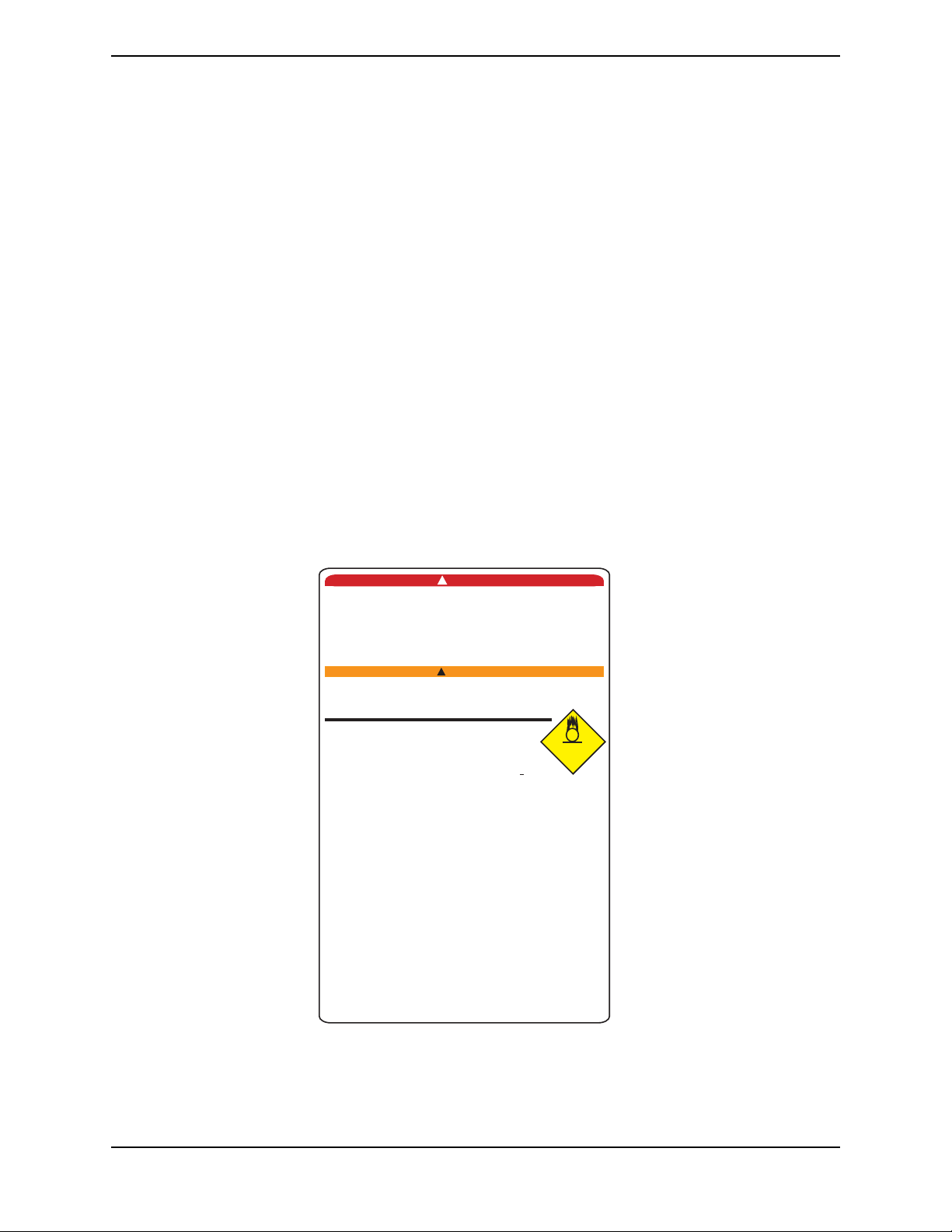
Cylinder Prefill Inspection
WARNING
Use only cylinders that have the Invacare HomeFill II connection and the label, FIGURE 3.1 on page 15.
CAUTION
All cylinders MUST be inspected before attempting to fill. Otherwise, injury or damage may occur.
NOTE: For this procedure, refer to FIGURE 3.1 on page 15.
Hydrostatic Testing Date
Aluminum cylinders MUST undergo testing every five years.
WARNING
DO NOT fill cylinders that have not been tested in the past five years. Otherwise, serious personal injury may result. Contact your dealer for replacement.
HomeFill™II Compressor 14 Part No 1141487
SECTION 3—CHECKLIST AND CYLINDER INSPECTION
External Examination
1. Examine the outside of the cylinder for the following conditions, and replace the cylinder if they exist:
• Dents or dings
•Arc burns
•Oil or grease
• Any other signs of damage that might cause a cylinder to be unacceptable or
unsafe for use.
2. Examine the cylinder for evidence of fire or thermal damage. Evidence includes charring or blistering of the paint, or other protective coating or heat sensitive indicator. If fire or thermal damage is found, replace the cylinder.
3. Inspect the Invacare valve for the following and replace if found:
• Debris, oil or grease
• Noticeable signs of damage
• Signs of corrosion inside the valve
• Signs of excessive heat or fire damage
DANGER
Improper filling or abuse of this cylinder, or failure to follow
these safety instructions may cause serious bodily injury or
death. High pressure oxidizing gas vigorously accelerates
combustion.
DO NOT alter or modify cylinder or related components.
DO NOT use Oil or Grease. Keep cylinder, cylinder valve, all
equipment and connections free of oil and grease to avoid
viole nt ignitio n resulting in serious bodily injur y or death.
For medical applications. Use only
practitioner. Uninterrupted use of
over a long duration, without
content of arterial blood, may be harmful.
Oxygen Cylinders filled by the Venture HomeFill
shall be used for personal use only. "Not to be
filled for resale or use by professional users".
This cylinder is to b e used with the Invacare Venture
HomeFill system. This cylinder contains
oxygen produced by an oxygen concentrator using
the pressure swing adsorption process.
DO NOT handle cylinder or use contents until you are
professionally trained, including emergency procedures.
Use in accordance
Open valve slowly.
ecure cylinder during s
S
area.
Keep away from heat, flame and spark. Keep out of
reach of children. DO NOT drop.
Transfilling of this gas is performed by Venture HomeFill Only.
Cylinders that have been refinished and/or exposed to
elevated temperatures must be hydrostatically tested before
filling.
Cylinder temperature
Aluminum cylinders subject
temperatures in excess of 350°F
service and condemned by trained
caustic paint strippers. Valve and safety relief devices must be
removed and replaced by trained and authorized
personnel. DO NOT alter or change valve assembly.
Invacare Corporation
2101 E. Lake Mary Blvd.
Sanford, FL 32773
1-800-832-4707
!
!
WARNING
monitoring its effect on
with Venture HomeFill Operator’s
Close valve after each use
torage and use. No smoking in cylinder
should not exceed 125°F (52°C).
to the action of
must be
DO NOT REMOVETHIS PRODUCT LABEL
Not for Commercial Resale
as directed by a
high concentrations
personnel. DO NOT use
Part Number 1125090 Rev B - 11/04
licensed
oxygen
OXYGEN
+
93 + 3%
Manual.
and when empty.
fire or heated to
withdrawn from
of oxygen
2
FIGURE 3.1 Cylinder Prefill Inspection
Part No 1141487 15 HomeFill™II Compressor

SECTION 4—COMPRESSOR OPERATION
SECTION 4—COMPRESSOR OPERATION
Connecting/Disconnecting Cylinder to/from Compressor
Connecting the Cylinder to the Compressor
WARNING
DO NOT modify any connections on the HomeFill II compressor.
NEVER use tools of any kind to connect/disconnect the cylinder and the compressor. Otherwise, severe injury and/or damage may occur.
DO NOT drop oxygen cylinders. Use two hands when handling/transporting oxygen cylinders. Otherwise, injury or damage may occur.
DO NOT use a liquid leak detector to test for leaks.
NOTE: For this procedure, refer to FIGURE 4.1 on page 17 and FIGURE 4.2 on page 18.
1. Examine the cylinder gauge. If the cylinder pressure is less than 1500 psig., proceed to STEP 2.
NOTE: If the cylinder pressure is greater than 1500 psig, DO NOT attempt to top off the cylinder. It may not fill. Bleed the cylinder or select another cylinder.
2. Set the regulator flow dial on the cylinder to Off (Detail “B” of FIGURE 4.2).
3. Remove the cylinder and connector fillport covers (if present).
CAUTION
DO NOT connect the outlet (cannula) connection to the HomeFill II unit. Otherwise, the conserving cylinder will not work properly.
NOTE: On older models, the green dots do not exist.
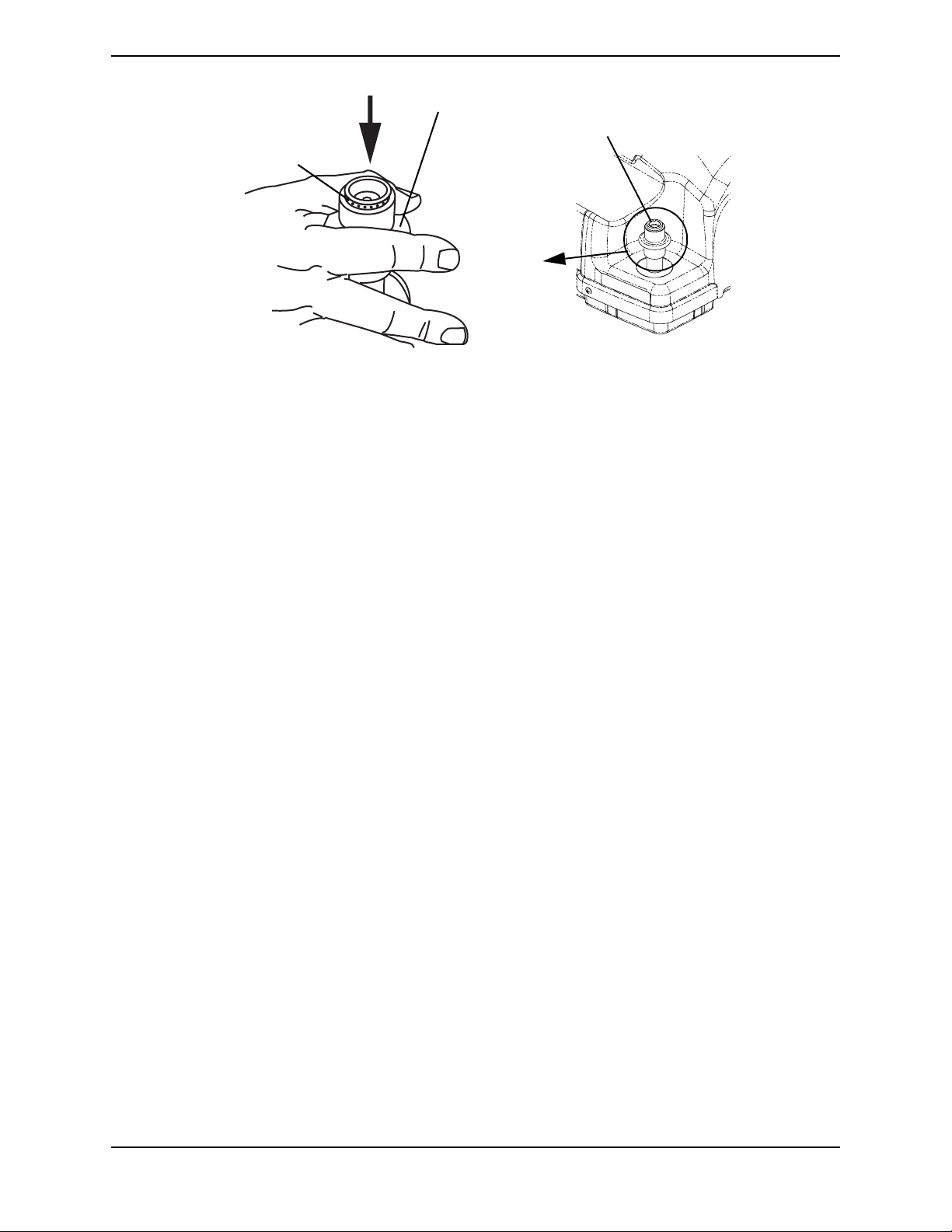
4. To reset the connector, momentarily push down on the outer ring (sleeve) of the connector fillport until GREEN dots are visible (FIGURE 4.1).
NOTE: If the outer ring (sleeve) is in the up position (GREEN dots not visible), the connector
fillport will not be able to accept the cylinder fillport. Pushing down momentarily will reset the
connector fillport (GREEN dots visible) to accept the cylinder fillport.
HomeFill™II Compressor 16 Part No 1141487
SECTION 4—COMPRESSOR OPERATION
PUSH
DOWN
Outer Ring (Sleeve)
Connector Fillport
GREEN Dots
BEFORE
COUPLING
CYLINDER,
PUSH DOWN
ON SLEEVE
UNTIL
GREEN DOTS
ARE VISIBLE.
FIGURE 4.1 Resetting Connector Fillport
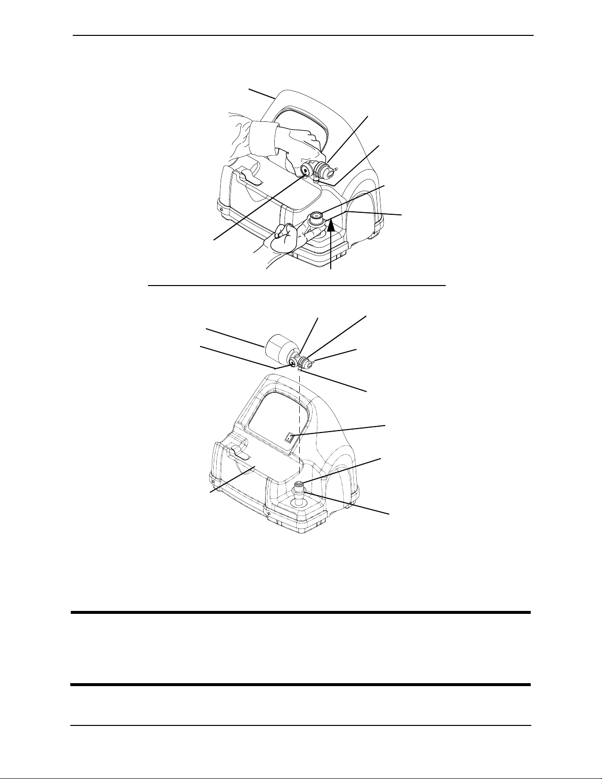
5. Grasp the cylinder/regulator assembly in the area behind the cylinder gauge in FIGURE 4.2 on page 18.
6. Position the cylinder in the compressor cradle (Detail “A” of FIGURE 4.2).
7. Align the cylinder fillport with the connector fillport (Detail “B” of FIGURE 4.2).
8. Pull up on the outer ring (sleeve) of the connector fillport while pushing down on the cylinder/regulator assembly to couple the cylinder fillport into the connector fillport (Detail “A” of FIGURE 4.2).
NOTE: The cylinder is properly connected when an audible “click” is heard.
Part No 1141487 17 HomeFill™II Compressor
SECTION 4—COMPRESSOR OPERATION
DETAIL “A”
Compressor
Cylinder
Gauge
DETAIL “B”
Cylinder/Regulator
Assembly
Cylinder
Fillport
Connector
Fillport
Outer Ring
(Sleeve)
PULL UP
Regulator
Cylinder
Cylinder
Gauge
Compressor
Cradle
NOTE: Fillport covers not shown for clarity.
FIGURE 4.2 Connecting the Cylinder to the Compressor
Disconnecting Cylinder From Compressor
Regulator
Flow Dial
Outlet (Cannula)
Connection
Cylinder Fillport
Power
Switch
Connector
Fillport
Outer Ring
(Sleeve)
WARNING
DO NOT modify any connections on the HomeFill II compressor. NEVER use tools of any kind to connect/disconnect the cylinder and the compressor. Otherwise, severe injury and/or damage may occur.
NOTE: For this procedure, refer to FIGURE 4.3 on page 19.
HomeFill™II Compressor 18 Part No 1141487
 Loading...