

Invacare G50 Service Instructions Manual
Invacare ® G50
SERVICE INSTRUCTIONS
Edition: 20.03.11
SERVICE INSTRUCTIONS
Invacare
®
- G50
2
These instructions contain information about:
Testing work
Repair Instructions
This manual is part of the instructions for use.
Service addresses
Invacare Austria GmbH
Herzog Odilostrasse 101
A-5310 Mondsee
Austria
: +43 6232 5 53 50
Fax: +43 6232 5 53 54
@: info@invacare-austria.com
WWW: www.invacare.at
Invacare n.v.
Autobaan 22
B-8210 Loppem (Brugge)
Belgium
: +32 (0)50 83 10 10
Fax: +32 (0)50 83 10 11
@: belgium@invacare.com
WWW: www.invacare.be
Invacare AG
Benkenstraße 260
CH-4108 Witterswil
Switzerland
: +41 (0)61487 70 80
Fax: +41 (0)61487 70 81
@: switzerland@invacare.com
WWW: www.invacare.ch
Invacare Aquatec GmbH
Alemannenstraße 10
88316 Isny
Deutschland
+49 (0)7562 70 00
Fax +49 (0)7562 7 00 66
@: info@invacare-aquatec.com
WWW: www.invacare-aquatec.de
Invacare A/S
Sdr. Ringvej 37
DK-2605 Brøndby
Danmark
(Kundeservice): +45 (0)36 90 00 00
Fax (Kundeservice): +45 (0)36 90 00 01
@: denmark@invacare.com
WWW: www.invacare.dk
Invacare® SA
c/ Areny s/n
Polígon Industrial de Celrà
E-17460 Celrà (Girona)
ESPAÑA
: +34 (0)972 49 32 00
Fax: +34 (0)972 49 32 20
@: contactsp@invacare.com
WWW: www.invacare.es
Invacare® Poirier SAS
Route de St Roch
F-37230 Fondettes
France
: +33 (0)247 62 64 66
Fax: +33 (0)247 42 12 24
@: contactfr@invacare.com
WWW: www.invacare.fr
Invacare ® - G50
SERVICE INSTRUCTIONS
3
Invacare® Ltd
Pencoed Technology Park
Pencoed
Bridgend CF35 5HZ
United Kingdom
(Customer services): +44 (0)1656 77 62 22
Fax (Customer services): +44 (0)1656 77 62 20
@: uk@invacare.com
WWW: www.invacare.co.uk
Invacare Mecc San s.r.l.
Via dei Pini, 62
I - 36016 Thiene (VI)
Italia
: +39 0445 38 00 59
Fax: +39 0445 38 00 34
@: italia@invacare.com
WWW: www.invacare.it
Invacare Ireland Ltd.
Unit 5 Seatown Business Campus
Seatown Rd, Swords
County Dublin
Ireland
: +353 18 10 70 84
Fax: +353 18 10 70 85
@: ireland@invacare.com
WWW: www.invacare.ie
Invacare® AS
Grensesvingen 9
Postboks 6230
Etterstad
N-0603 Oslo
Norge
(Kundeservice): +47 (0)22 57 95 00
Fax (Kundeservice): +47 (0)22 57 95 01
@: norway@invacare.com
@: island@invacare.com
WWW: www.invacare.no
Invacare® B.V.
Celsiusstraat 46
NL-6716 BZ Ede
Nederland
: +31 (0)318 69 57 57
Fax: +31 (0)318 69 57 58
@: nederland@invacare.com
@: csede@invacare.com
WWW: www.invacare.nl
Invacare Lda
Rua Estrada Velha, 949
P-4465-784 Leça do Balio
Portugal
: +351 225 10 59 46
: +351 225 10 59 47
Fax: +351 225 10 57 39
@: portugal@invacare.com
WWW: www.invacare.pt
SERVICE INSTRUCTIONS
Invacare
®
- G50
4
(Kundtjänst): +46 (0)8 761 70 90
Återförsäljare:
Invacare® AB
Fagerstagatan 9
S-163 91 Spånga
Sverige
Tillverkare:
Invacare® Deutschland GmbH
Kleiststraße 49
D-32457 Porta Westfalica
Deutschland
Fax (Kundtjänst): +46 (0)8 761 81 08
@: sweden@invacare.com
@: finland@invacare.com
WWW: www.invacare.se
MÖLNDAL
: +46 (0)31 86 36 00
Fax: +46 (0)31 86 36 06
@: ginvacare@invacare.com
LANDSKRONA
: +46 (0)418 2 85 40
Fax: +46 (0)418 1 80 89
@: linvacare@invacare.com
OSKARSHAMN
: +46 (0)491 1 01 40
Fax: +46 (0)491 1 01 80
@: oinvacare@invacare.com
Eastern
european
countries
European Distributor
Organisation (EDO)
Kleiststraße 49
D-32457 Porta Westfalica
Deutschland
+49 (0)5731 75 45 40
Fax +49 (0)5731 75 45 41
@: edo@invacare.com
WWW: www.invacare.de

Invacare ® - G50
SERVICE INSTRUCTIONS
5
Table of Contents
Chapter Page
TABLE OF CONTENTS 5
1 INTRODUCTION 8
1.1 General information 8
1.2 Notes on transport 8
1.3 Definition and representation of information and safety information in this manual 9
1.4 Hazard symbols and symbols used 10
1.5 Images in this manual 11
2 SAFETY AND FITTING INSTRUCTIONS 12
2.1 Before any inspection or repair work 12
2.2 Personal safety equipment 12
2.3 General safety information and information about fitting / removal 12
3 TIGHTENING TORQUES 14
4 ALLOCATION OF THE SUB-ASSEMBLIES AND COMPONENTS 15
5 MAINTENANCE PLAN (ONCE A YEAR) 16
6 OPERATIONAL FAULTS 19
6.1 Operational faults on wheelchair with ACS 19
6.1.1 Diagnosing drive faults 19
6.1.2 Diagnosing problems with electric actuators 21
6.1.3 Error Codes and Diagnostic Codes 22
7 REPAIR WORK 26
7.1 General warning information on installation work 26
7.2 Replacing front cowling 27
7.2.1 Disassembly 27
7.2.2 Assembly 28
7.3 Replacing rear cowling / replacing rear lights 29
7.3.1 Disassembly 29
7.3.2 Assembly 30

SERVICE INSTRUCTIONS
Invacare
®
- G50
6
7.4 Replacing the side cowling 31
7.4.1 Placing seat in service position 31
7.4.2 Remove the rear cowling 32
7.4.3 Removing the side cowling 33
7.4.4 Assembly 36
7.5 Replacing the headlights 37
7.5.1 Placing seat in service position 37
7.5.2 Unmounting the headlights 39
7.5.3 Assembly 40
7.6 Replacing a motor 41
7.6.1 Disassembly 41
7.6.2 Assembly 46
7.7 Replacing the rear rocker / adjusting toe and camber 48
7.7.1 Disassembly 48
7.7.2 Assembly 51
7.7.3 Adjusting the camber 52
7.7.4 Adjusting the toe-in 52
7.8 Replacing the front shock absorbers 54
7.8.1 Disassembly 54
7.8.2 Assembly 58
7.9 Replacing the Bowden cable of the hand brake / adjusting the brake 59
7.9.1 Replacing the Bowden cable 59
7.9.2 Assembly 63
7.9.3 Adjusting the hand brake 63
7.10 Replacing the Bowden cable of the declutching mechanism 65
7.10.1 Replacing the Bowden cable 65
7.10.2 Assembly 69
7.11 Replacing the seat frame (EBAS) 70
7.11.1 Placing seat in service position 70
7.11.2 Disassembly 72
7.11.3 Assembly 76
7.12 Replacing electronics components 77
7.12.1 Replacing the power module 77
7.12.2 Replacing other electronic components 78
7.13 Changing the batteries 79
7.13.1 Tilting the seating system forward 80
7.13.2 Removing the batteries 81
7.13.3 Connecting the New Batteries 82
7.13.4 How to handle damaged batteries correctly 83
7.14 Checking and replacing the main fuse 84
7.14.1 Placing seat in service position 84
7.15 Checking the cables 87
7.15.1 Placing seat in service position 87
7.16 Replacing the ACS Remote 90
7.17 Updating the driving program 92

Invacare ® - G50
SERVICE INSTRUCTIONS
7
7.18 Retrofitting the joystick left/right 93
7.18.1 Placing seat in service position 93
7.18.2 Retrofitting 95
7.19 Repairing a flat tyre 97
7.19.1 Repairing a flat tyre (type 4.00-8" pneumatic tyres) 97
7.19.2 Repairing a flat tyre (type 3.10/4.50-6 pneumatic tyres) 99
7.20 Replacing the safety belt 101
7.21 Testing an actuator motor 101
8 REFURBISHMENT 102
8.1 Configuration table 102

SERVICE INSTRUCTIONS
Invacare
®
- G50
8
1 Introduction
1.1 General information
• Service and maintenance work must be carried out taking this service manual into account.
• It is imperative that you observe safety information.
• Information about operation or about general maintenance and care work on the mobility aid
should be taken from the operating manual.
• You can find information about ordering spare parts in the spare parts catalogue.
• Only use original Invacare® spare parts. The guarantee will become invalid if other spare
parts are used!
• We reserve the right to make any alterations on the grounds of technical improvements.
• The mobility aid may only be maintained and overhauled by qualified personnel.
• The minimum requirement for service technicians is suitable training, such as in the cycle or
orthopaedic mechanics fields, or sufficiently long-term job experience.
- Experience in the use of electrical measuring equipment (multimeters) is also a requirement.
- Special Invacare® training is recommended.
• Alterations to the mobility aid which occur as a result of incorrectly or improperly executed
maintenance or overhaul work lead to the exclusion of all liability on the side of INVACARE.
• If you have any problems or questions please contact Invacare® Service.
1.2 Notes on transport
• If the mobility aid has to be shipped back to the manufacturer for major repairs, you should
always use the original packaging for transport.
• Please attach a precise description of the fault.
Invacare ® - G50
SERVICE INSTRUCTIONS
9
1.3 Definition and representation of information and safety
information in this manual
Different types of information and signal words are used throughout this manual.
HAZARD!
The signal word "HAZARD!" refers to immediate hazards.
• The following lines in italics refer to actions which serve to avoid such hazards.
WARNING!
The signal word "WARNING!" refers to possibly-occurring hazards which can lead to
death or serious injuries if they are not avoided.
• The following lines in italics refer to actions which serve to avoid such hazards.
ATTENTION!
The signal word " ATTENTION!" refers to possibly-occurring hazards which can lead to
minor injuries and/or material damage if they are not avoided.
• The following lines in italics refer to actions which serve to avoid such hazards.
CAUTION!
The signal word "CAUTION!" refers to hazards which could lead to material damage if
they are not avoided.
• The following lines in italics refer to actions which serve to avoid such hazards.
Note
The signal word "Note" is used to denote general information which simplifies the handling of
your product and refers to special functions.
SERVICE INSTRUCTIONS
Invacare
®
- G50
10
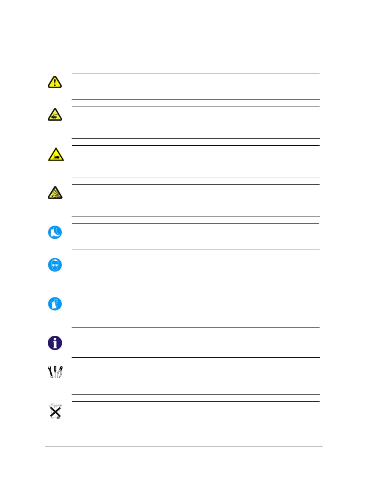
1.4 Hazard symbols and symbols used
Different types of hazard symbols and symbols are used throughout this manual.
General hazards
This symbol warns you of general hazards!
• Always follow the instructions to avoid injury to the user or damage to the product!
BURN HAZARD!
This symbol warns you of the danger of chemical burns, for example due to the discharge
of battery acids!
• Always follow the instructions to avoid injury to the user or damage to the product!
DANGER OF CRUSHING!
This symbol warns you of crushing hazards due to inattentive working with heavy
components.
• Always follow the instructions to avoid injury to the user or damage to the product!
EXPLOSION HAZARD!
This symbol warns you of an explosion hazard, which can be caused by excessive tyre
pressure in a pneumatic tyre.
• Always follow the instructions to avoid injury to the user or damage to the product!
Wear safety shoes
The symbol refers to the requirement for wearing safety shoes.
• Wear standardised safety shoes during all work.
Wear eye protection
This symbol refers to the requirement for wearing eye protection, for example when
working with batteries.
• Wear eye protection when this symbol is shown.
Wear safety gloves
This symbol refers to the requirement for wearing safety gloves, for example when
working with batteries.
• Wear safety gloves when this symbol is shown.
Note
This symbol identifies general information which is intended to simplify working with your product
and which refers to special functions.
Requirements:
• This symbol identifies a list of various tools, components and items which you will need in
order to carry out certain work. Please do not attempt to carry out the work if you do not
have the listed tools available.
Always dispose used or damaged batteries correctly
The symbol refers to information for the correct disposal of used or damaged batteries.

Invacare ® - G50
SERVICE INSTRUCTIONS
11
1.5 Images in this manual
The detailed images in this manual are given digits to identify various components. Component
numbers in text and operational instructions always relate to the image directly above.
SERVICE INSTRUCTIONS
Invacare
®
- G50
12
2 Safety and fitting instructions
These safety instructions are intended to prevent accidents at work, and it is imperative that they
are observed.
2.1 Before any inspection or repair work
• Read and observe this repair manual and the associated operating manual!
• Observe the minimum requirements for carrying out the work (see chapter entitled „General
information)!
2.2 Personal safety equipment
Safety shoes
The mobility device, and some of its components, are very heavy. These parts can result
in injuries to the feet if they are allowed to drop.
• Wear standardised safety shoes during all work.
Eye protection
It is possible that battery acid can be discharged when working on defective batteries or
when handling batteries improperly.
• Always wear eye protection when working on any defective or possibly defective batteries.
Safety gloves
It is possible that battery acid can be discharged when working on defective batteries or
when handling batteries improperly.
• Always wear acid-proof safety gloves when working on any defective or possibly defective
batteries.
2.3 General safety information and information about fitting / removal
WARNING: Danger of crushing!
Various components such as the drive unit, batteries, seat etc are very heavy. This results
in injury hazards to your hands!
• Please note the high weight of some components! This applies especially to the removal of
drive units, batteries and the seat.
WARNING!
Injury hazard if the vehicle starts moving unintentionally during repair work!
• Switch the power supply off (ON/OFF key)!
• Engage the drive!
• Before raising the vehicle, secure the wheels by blocking them with wedges!
ATTENTION!
Fire and burn hazard due to electrical short-circuit!
• The mobility device must be completely switched off before removal of voltage-carrying
components! To do this, remove the batteries.
• Avoid short-circuiting the contacts when carrying out measurements on voltage-carrying
components!
Invacare ® - G50
SERVICE INSTRUCTIONS
13
CAUTION!
Danger of burns from hot surfaces on the motor!
• Allow the motors to cool down before commencing work on them.
ATTENTION!
Injury hazard and danger of damage to vehicle due to improper or incomplete
maintenance work!
• Use only undamaged tools in good condition.
• Some moving parts are mounted in sockets with PTFE coating (Teflon™). Never grease
these sockets!
• Never use "normal" nuts instead of self-locking nuts.
• Always use correctly-dimensioned washers and spacers
• When reassembling, always replace any cable ties which were cut during dismantling.
• After completing your work / before renewed start-up of the mobility device, check all
connections for tight fitting.
• After completing your work / before renewed start-up of the mobility device, check all parts for
correct locking.
• Only operate the vehicle with the approved tyre pressures (see technical data).
• Check all electrical components for correct function. Please note that incorrect polarity can
result in damage to the electronics.
• Always carry out a trial run at the end of your work.
Note
Mark all current settings for the mobility aid (seat, armrests, backrest etc.), and the associated
cable connecting plugs, before dismantling. This makes reassembly easier.
All plugs are fitted with mechanical safety devices which prevent release of the connecting plugs
during operation. To release the connecting plugs the safety devices must be pressed in. When
reassembling ensure that these safety devices are correctly engaged.
WARNING!
Any changes to the drive program can affect the driving characteristics and the tipping
stability of the vehicle!
• Changes to the drive program may only be carried out by trained Invacare® specialist
dealers!
• Invacare® supplies all mobility aids with a standard drive program ex-works. Invacare® can
only give a warranty for safe vehicle driving behaviour - especially tipping stability - for this
standard drive program!
SERVICE INSTRUCTIONS
Invacare
®
- G50
14
3 Tightening torques
The tightening torques stated in the following list are based on the thread diameter for the nuts and
bolts for which no specific values have been determined. All values assume dry and de-greased
threads.
Thread
M4 M5 M6 M8 M10 M12 M14 M16
Tightening torque
in Nm ±10%
3 Nm 6 Nm 10 Nm 25 Nm 49 Nm 80 Nm 120 Nm 180 Nm
CAUTION!
Damage can be caused to the mobility device due to improperly tightened screws, nuts or
plastic connections.
• Always tighten screws, nuts etc to the stated tightening torque.
• Only tighten screws or nuts which are not listed here fingertight.
Invacare ® - G50
SERVICE INSTRUCTIONS
15
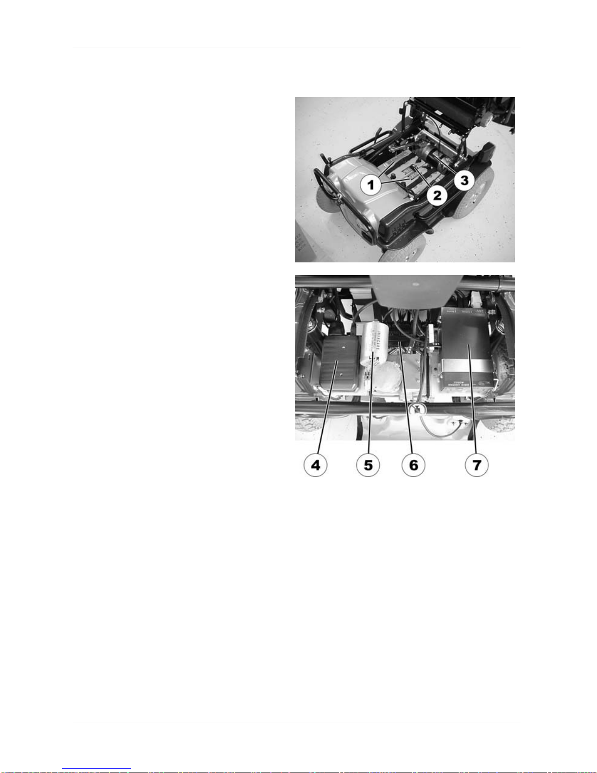
4 Allocation of the sub-assemblies and components
Under the seat:
1) Batteries
2) Main fuse
3) Drive
Under the rear cowling
4) CLAM (Combined Light and Actuator
Module) (only installed if the
wheelchair is equipped with electric
adjustment options)
5) Steering servo
6) Power module (partially covered in
picture)
7) Servo-Light-Module
SERVICE INSTRUCTIONS
Invacare
®
- G50
16
5 Maintenance plan (once a year)
Component Check for Measures
Seating Unit
Armrests / Armrest pads
• Damage / wear • Replace
• Check that all screws are
tight
• Tighten
Backrest (Cushion / Sling)
• Damage / wear • Replace
Backrest (Frame, Fixation
parts)
• Damage / wear • Replace
• Check that all screws are
tight
• Tighten
Seat cushion
• Damage / wear • Replace
Actuator / actuator cable
(if available)
• Damage • Replace
• Function • Check that the cable is
firmly connected, if
necessary replace cable
or actuator (See "
Testing
an actuator motor
" on
page
101)
• Check function of the
CLAM, if necessary
replace CLAM (See
"
Replacing electronics
components
" on page
77)
• Check that all screws are
tight
• Tighten
Opening mechanism of the seat unit (Easy Battery Access system)
Unlocking mechanism
• Damage, correct function • Replace damaged/worn
parts
Swing-up mechanism,
latching mechanism, gas
pressure spring
• Damage, correct function • Replace
• Check that all screws are
tight
• Tighten
Electrical System
Driving Programme
• Check the programme
version of the driving
electronics. Is there a
newer version available?
• Update the software. See
"
Updating the driving
program
" on page 92
Batteries / battery cable
• Damage • replace (See "
Changing
the batteries
" on page
79)
• Battery voltage • Charge batteries
Invacare ® - G50
SERVICE INSTRUCTIONS
17
Component Check for Measures
• Check that the cable
clamps are firmly
attached to the battery
terminals
• Tighten
Battery fixation belts /
buckles
• Damage • Replace
• Firmly attached • Tighten
Cables / cable looms
• Damage • Replace
• Plug-in connections are
firmly connected
• Firmly press the
connection together (See
"
Checking the cables"
on page
87)
Joystick box / bus cable
• Damage • Replace
• Check that all plug-in
connections are firmly
connected
• Firmly press the plug-in
connection together (See
"
Checking the cables"
on page
87)
• Check that all screws are
tight
• Tighten
• Function • Send in to Invacare to be
repaired, if necessary
replace (See "
Replacing
the ACS Remote
" on
page
90)
Lighting
• Light bulbs defective • Replace
• Casing / glass damaged • Replace
• Position / angle out of
adjustment
• Adjust
Frame
Frame (chassis) / Battery
cradle
• Check fixation, weld
seams and battery cradle
for damage
• Tighten screws, replace
components
Wheels / Tyres
Drive wheels
• Check for tight fit and
axial run out
• Adjust
Steering wheels
• Check for tight fit, check
required motor-to-body
clearance and axial run
out
• Replace wheels or wheel
bearings.
Pneumatic tyres
• Damage • Repair or replace, if
damaged (See
"
Repairing a flat tyre" on
page
97)
Steering mechanism
SERVICE INSTRUCTIONS
Invacare
®
- G50
18
Component Check for Measures
Steering connecting rods /
steering connecting rod
heads
• Damage • Replace
• Check that all screws are
tight
• Tighten
Servo
• Function • Check that the plug-in
connection of the servo
cable is firmly connected,
if necessary replace the
cable or servo
• Check the function of the
Servo-Light-Module, if
necessary replace
Drive
Drive unit
• Function
• Check coupling
mechanism
• Replace (See
"
Replacing a motor" on
page
41)
• Tighten screws/nuts,
adjust or replace if
necessary
Coupling mechanism
• Function • Adjust, if necessary
replace damaged part
Parking brake
• Function • Adjust
Legrests
Legrests
• Check welding seams,
locking devices, foot
plates for damage
• Replace
• Check that all screws are
tight
• Tighten
• Check functions • Replace actuator/cable
(See "
Testing an
actuator motor
" on page
101)
• Clean and check the
contacts of the legrest
mounting brackets, if
necessary replace.
Actuator (on electric
legrests)
Invacare ® - G50
SERVICE INSTRUCTIONS
19
6 Operational Faults
6.1 Operational faults on wheelchair with ACS
In the event of problems with the wheelchair, please proceed as follows:
• Begin by assessing the possible cause of disturbance on the basis of the following tables.
• Check the remote status display. Evaluate the flashing error code.
• Carry out the necessary examinations and repairs as recommended in the following table.
6.1.1 Diagnosing drive faults
PROBLEM
OTHER
SYMPTOMS
POSSIBLE
CAUSE
SOLUTION DOCUMENTATION
Wheelchair
will not
start up
Status display
on the remote
illuminates as
usual and does
not display an
error code
Drive motor
possibly faulty
• Replace drive
motor
See "Replacing a motor"
on page
41
Status display
on the remote is
not illuminated
Batteries
possibly faulty
• Replace
batteries
See "
Changing the
batteries
" on page 79
Battery possibly
deep-discharged
• Recharge
batteries
See instruction manual
Power supply to
remote possibly
interrupted
• Check main
fuse
See "
Checking and
replacing the main fuse
"
on page
84
• Check cable
between the
modules for
loose
connections or
damage
See "
Checking the
cables
" on page 87
Remote possibly
faulty
• Replace
remote on the
wheelchair in
order to
exclude the
possibility that
the remote is
the cause.
See "
Replacing the ACS
Remote
" on page 90
Status display
on the remote is
flashing
Various causes
• Evaluate error
code
See "
Error Codes and
Diagnostic Codes
" on
page
22

SERVICE INSTRUCTIONS
Invacare
®
- G50
20
PROBLEM
OTHER
SYMPTOMS
POSSIBLE
CAUSE
SOLUTION DOCUMENTATION
Wheelchair
judders
during drive
operation
None
Batteries
possibly faulty
(unstable
voltage)
• Replace
batteries
See "
Changing the
batteries
" on page 79
Drive motor(s)
possibly faulty
• Replace motor
See "
Replacing a motor"
on page
41
Batteries
are not
being
charged
None Batteries
possibly faulty
• Replace
batteries
See "
Changing the
batteries
" on page 79
LEDs flashing
on charger
Charger possibly
faulty
• Replace
charger
See charger instruction
manual
None Remote possibly
faulty
• Replace
remote
See "
Replacing the ACS
Remote
" on page 90
Battery possibly
deep-discharged
• Recharge
batteries
Pre-charge batteries with
a commercially available
battery charger.
Batteries
possibly faulty
• Replace
batteries
See "
Changing the
batteries
" on page 79

Invacare ® - G50
SERVICE INSTRUCTIONS
21
6.1.2 Diagnosing problems with electric actuators
Assess the cause of the fault involving an electric adjustment motor on the basis of the following
table:
PROBLEM
OTHER
SYMPTOMS
POSSIBLE
CAUSE
SOLUTION DOCUMENTATION
Electric
adjustment
motor not
reacting
Remote displays
flashing "E",
status diode on
light/adjustment
module does not
extinguish even
if the remote is
shut down or
disconnected
Light
/adjustment
module faulty
Replace
lighting/adjustment
module
See "
Replacing
electronics components
"
on page
77
None Cable possibly
severed or
damaged
• Check that
the cable
has not
been
severed or
damaged.
Replace
cable if
necessary
See "Checking the cables"
on page
87
Electric
adjustment
motor possibly
faulty
• Test
adjustmen
t motor
See "
Testing an actuator
motor
" on page 101
Remote
possibly faulty
• Replace
remote on
wheelchair
in order to
exclude
the
possibility
that the
remote is
the cause
of the
disturbanc
e.
See "
Replacing the ACS
Remote
" on page 90
SERVICE INSTRUCTIONS
Invacare
®
- G50
22
6.1.3 Error Codes and Diagnostic Codes
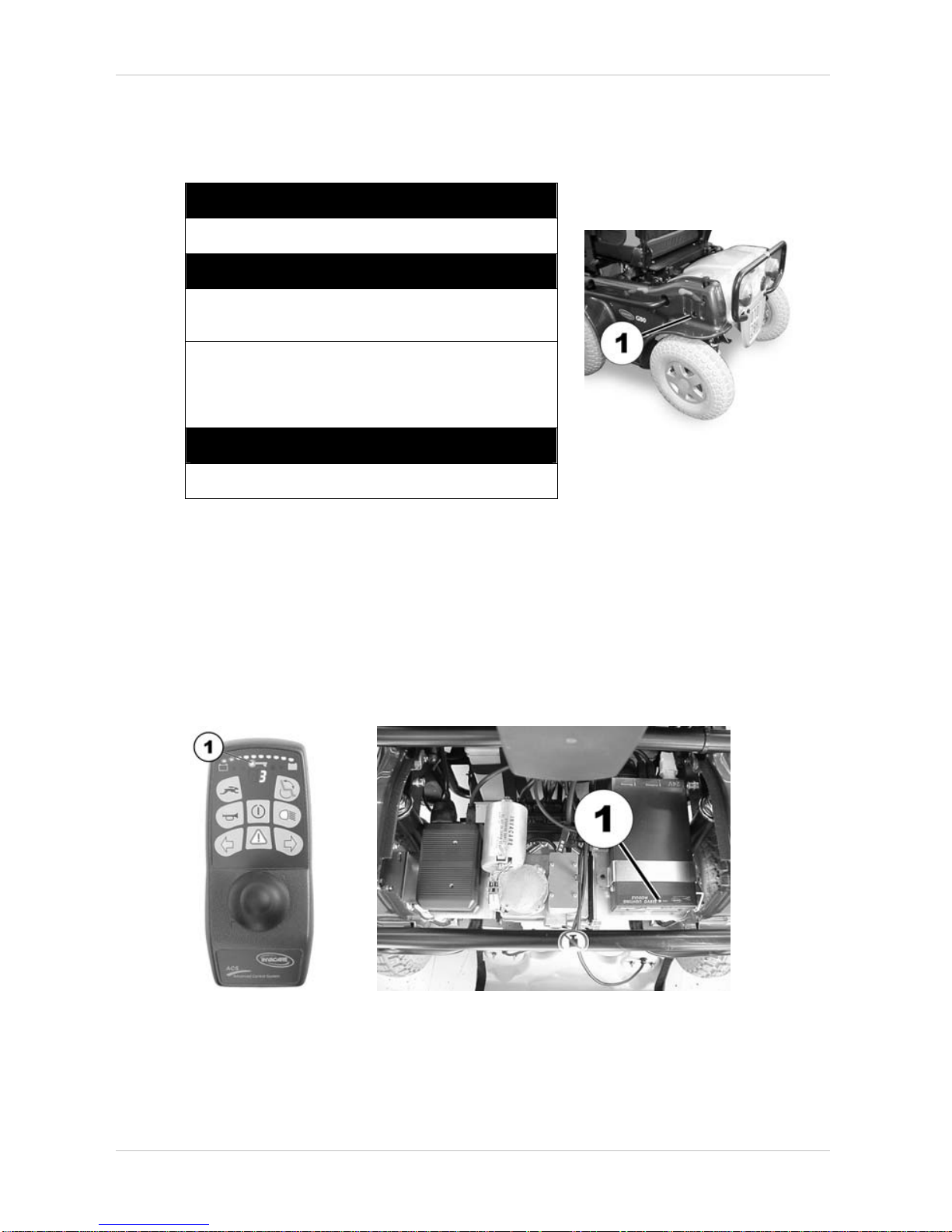
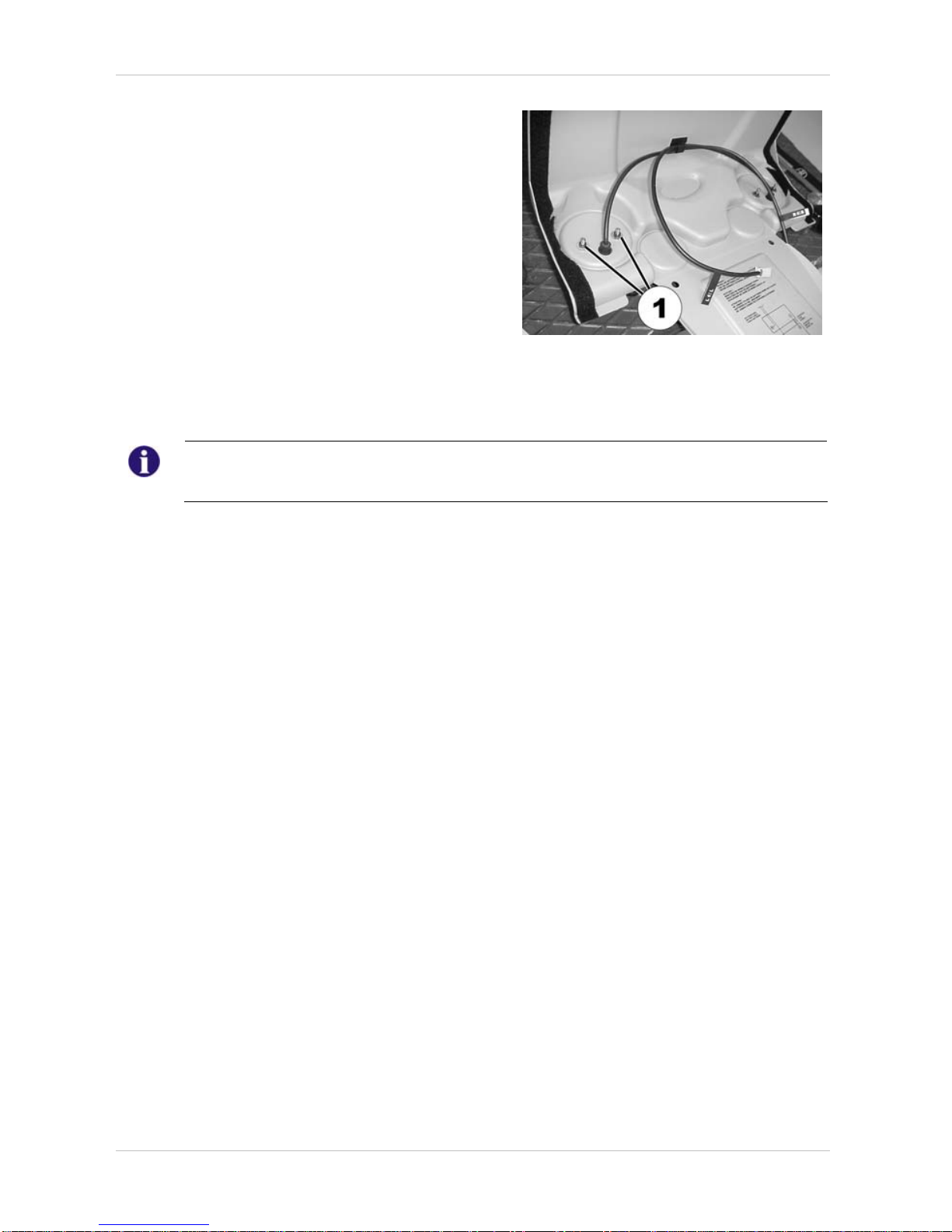
6.1.3.1 CLAM
LED of the CLAM lights up constantly:
CLAM is functioning correctly.
LED of the CLAM is off:
CLAM may not be connected. Check plug-in
connections.
The joystick box might be programmed with an
incorrect driving programme (for example after
having replaced the joystick box). Check driving
programme.
LED of the CLAM is flashing:
CLAM is defective. Replace CLAM.
Status display of the CLAM,
(visible through hole (1))
6.1.3.2 Joystick box / Servo-Light-Module
If the electronic system detects a fault this is indicated by a combined flashing code on the remote
and on the servo light module. Some faults can be remedied independently by the electronic
system. For this purpose, please switch the remote off and then on again. Please wait
approximately 5 seconds in each case before you switch the remote on again. If the fault can be
remedied, the flashing will stop on the status display. If the fault cannot be remedied by this,
please localise the fault by means of the following flashing codes.
Status display of
the remote (1)
Status display of the Servo-Light-Module (rear
cowling removed)
Invacare ® - G50
SERVICE INSTRUCTIONS
23
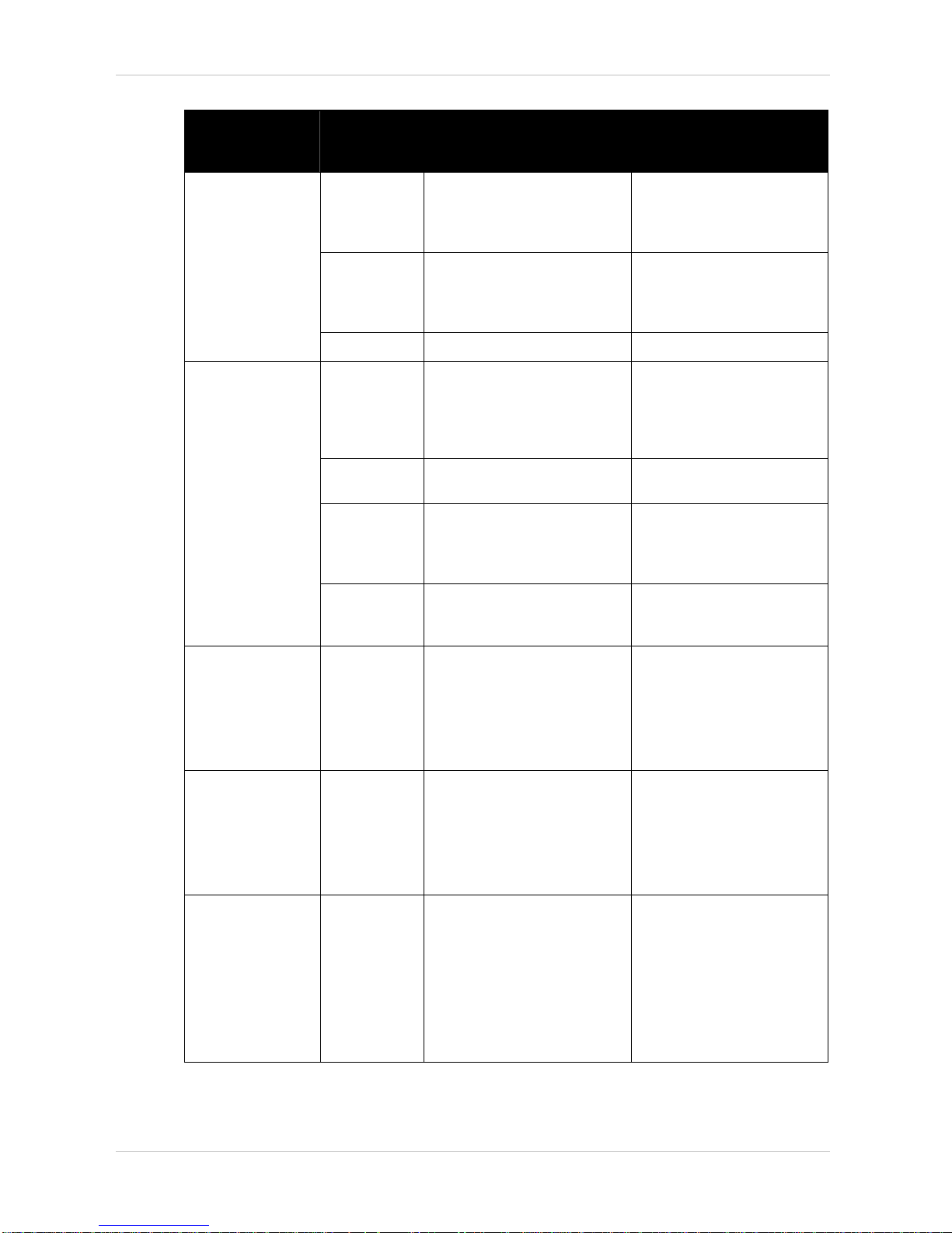
Remote status bar
indicator LED blink
code
Servo light
module LED
blink code
Cause Fault remedy
1 -
ACS module defective
• Replace faulty module
See "
Replacing
electronics
components
" on page 77
1
Plug on servo light module
(SLM) defective, or SLM
defective
• Replace faulty module
See "
Replacing
electronics
components
" on page 77
2
Error at servo motor
• Replace servo motor.
2 -
Faulty accessory (e.g. short
circuit on adjustment motor)
• Check accessory
connections, check
accessories See "
Testing
an actuator motor
" on
page
101
3
Potentiometer on servo motor
(steering) defective
• Replace potentiometer.
4
Lighting system defective
(error in SLM or in cabling)
• Check cable, replace
SLM. See "
Replacing
electronics
components
" on page 77
5
Steering disengaged
• Re-engage the steering:
Switch the electronics
system off and on again.
3 -
Motor connection
loose/defective or motor
defective (M1)
• Check the connecting
plug See "
Checking the
cables
" on page 87
• Replace motor See
"
Replacing a motor" on
page
41
4 -
Motor connection
loose/defective or motor
defective (M2)
• Check the connecting
plug See "
Checking the
cables
" on page 87
• Replace motor See
"
Replacing a motor" on
page
41
5 -
Magnetic brake defective or
drive disengaged
• Engage motor. Switch the
electronics system off and
on again.
• Check the connecting
plug
• Replace motor See
"
Replacing a motor" on
page
41

SERVICE INSTRUCTIONS
Invacare
®
- G50
24
Remote status bar
indicator LED blink
code
Servo light
module LED
blink code
Cause Fault remedy
6 -
Magnetic brake defective or
drive disengaged
• Engage motor. Switch the
electronics system off and
on again.
• Check the connecting
plug
• Replace motor See
"
Replacing a motor" on
page
41
7 -
Battery voltage too low
• Charge battery. See User'
Manual
7
Battery voltage too low (below
17V)
• Check battery
connections
• Check fuses.
• Check batteries and
replace if necessary. See
User' Manual
8 -
Battery voltage too high
• Turn on lighting
9
CANL error
• Check bus cable/data
cable for short circuit. An
open circuit or a short
circuit in one of the ACSModules can also cause
this error. See "
Checking
the cables
" on page 87
and "
Replacing
electronics
components
" on page 77
9
CANL error problems on the
CANL channel /
communication over CANL not
possible.
• Check bus cable for
continuity
10 -
CANH error
• Check bus cable/data
cable for short circuit. An
open circuit or a short
circuit in one of the ACSModules can also cause
this error. See "
Checking
the cables
" on page 87
and "
Replacing
electronics
components
" on page 77
10
CANH error problems on the
CANH channel /
communication over CANH
not possible.
• Check bus cable for
continuity
11 -
Maximum current time-out
(drive overloaded or
overheated)
• Switch the electronics
system off and on again.

Invacare ® - G50
SERVICE INSTRUCTIONS
25
Remote status bar
indicator LED blink
code
Servo light
module LED
blink code
Cause Fault remedy
11
Maximum current time-out
(servo motor overloaded or
overheated)
• Switch the electronics
system off and on again.
12
-
Compatibility problems
between ACS modules
• Remove all electronic
modules except the
Power Module and the
Remote. Re-attach
modules one by one to
determine which one is
causing the fault. Remove
incorrect module See
"
Replacing electronics
components
" on page 77
SERVICE INSTRUCTIONS
Invacare
®
- G50
26
7 Repair Work
7.1 General warning information on installation work
CAUTION!
Risk of damage to the vehicle! Collisions can be caused if shim rings are removed from
the drive wheels during installation work!
Shim rings are frequently placed between the drive shaft and the wheel hub to compensate
tolerances. Collisions can be caused if these shim rings are removed and not re-installed!
• Install all shim rings in exactly the same positions they were in before dismantling.
Invacare ® - G50
SERVICE INSTRUCTIONS
27
7.2 Replacing front cowling
Requirements:
• Open-end spanner 13 mm
NOTE
Please keep small parts such as screws and grommets safe during dismantling. Lay all small
parts down in such a way that they can be re-fitted in the correct order.
7.2.1 Disassembly
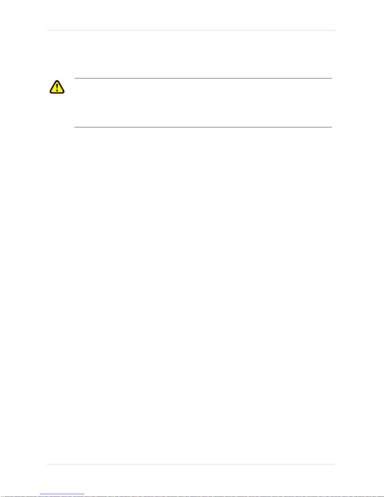
Removing the swing-away legrests
• Press the unlocking button (1) and swivel the footrest
outward.
• Remove the footrest in an upward direction.
Removing the fixed legrests
• Loosen the fixation screw with open-end
spanner 13 mm.
• Pull legrest out toward the front.
• Loosen and remove the knurled screws (A).
SERVICE INSTRUCTIONS
Invacare
®
- G50
28
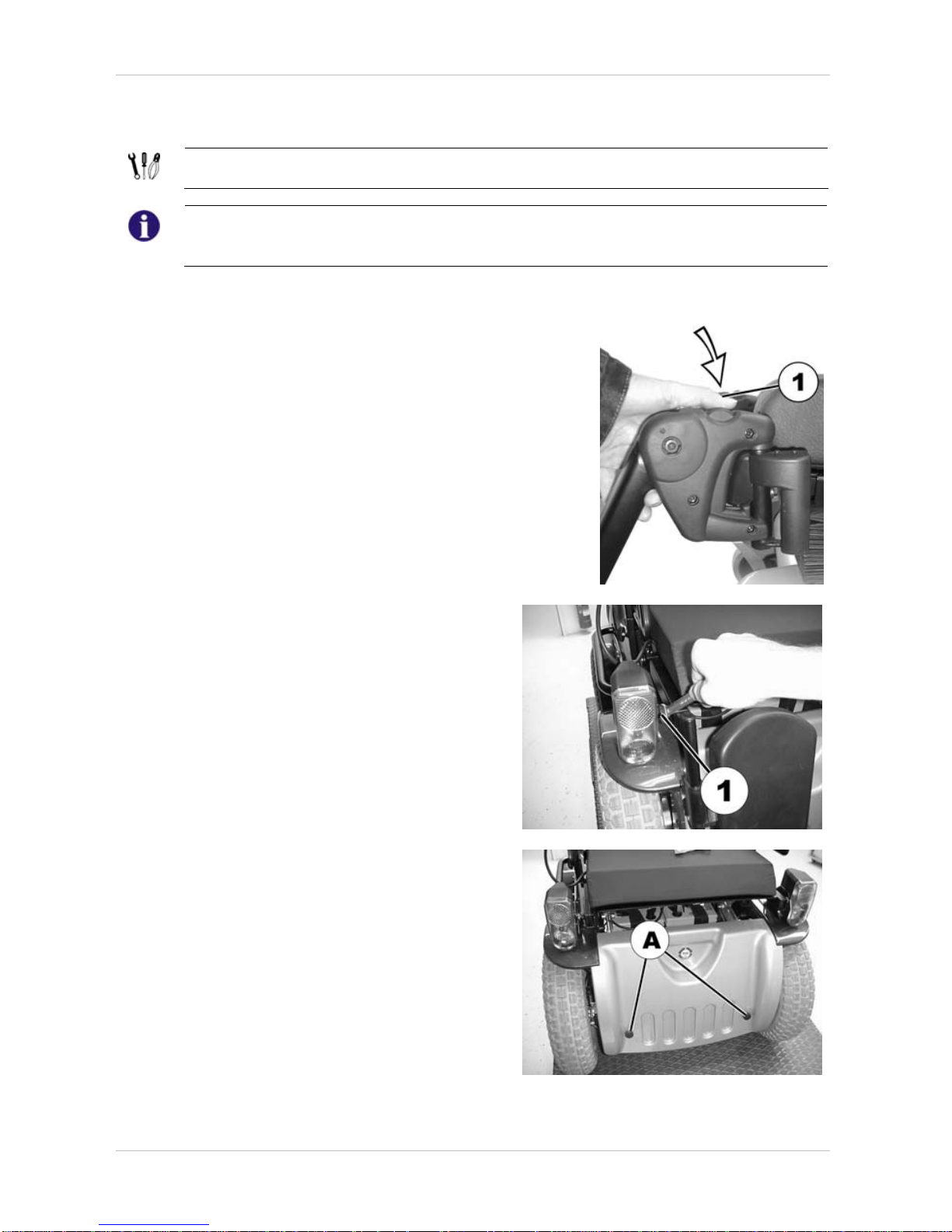
• Pull the cowling upward and forwards and
remove.
7.2.2 Assembly
The process of re-assembly is done in reverse order.
Invacare ® - G50
SERVICE INSTRUCTIONS
29
7.3 Replacing rear cowling / replacing rear lights
Requirements:
• 8mm open-ended spanner
NOTE
Please keep small parts such as screws and grommets safe during dismantling. Lay all small
parts down in such a way that they can be re-fitted in the correct order.
7.3.1 Disassembly
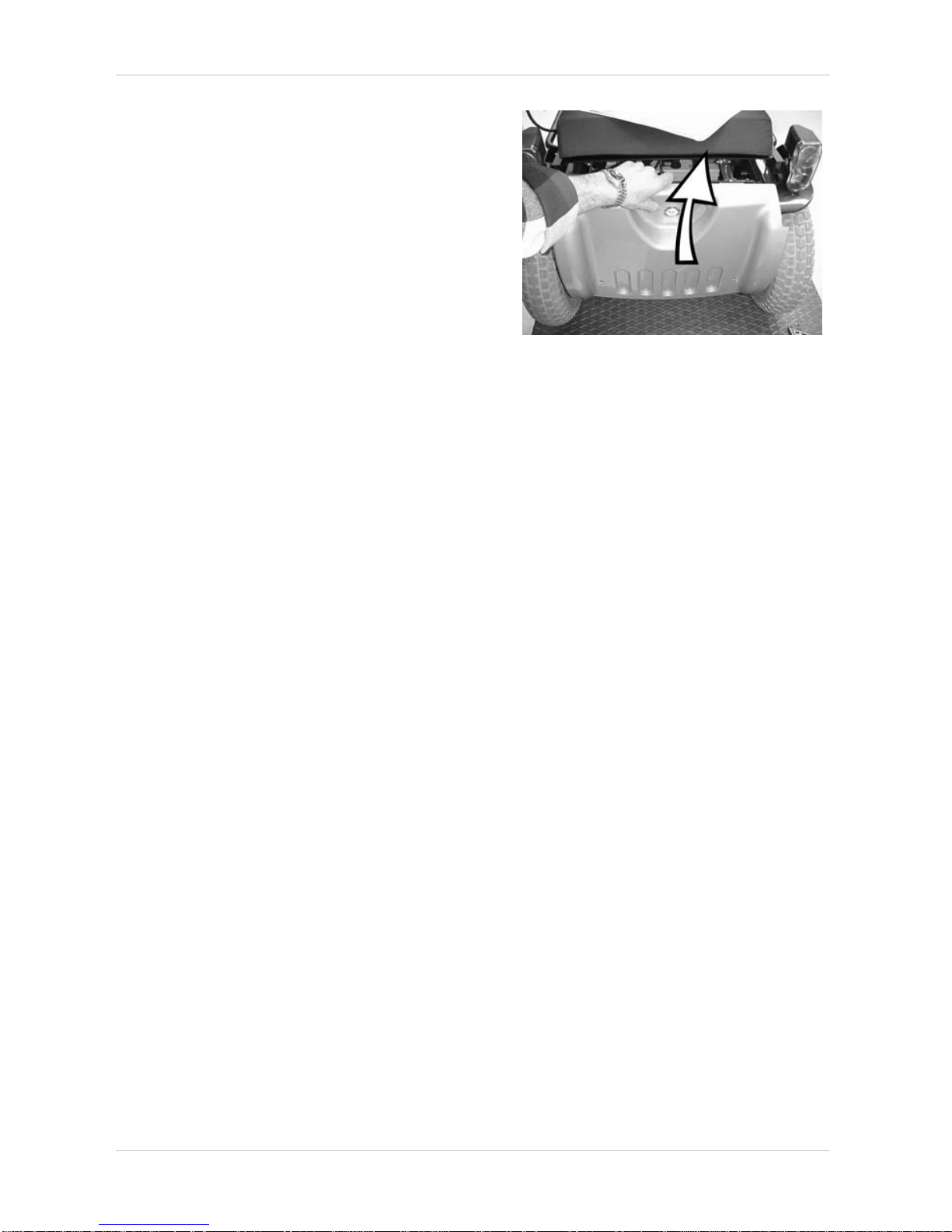
• Loosen and remove the knurled screws (A).
• Pull cowling upwards and backwards.
• Disconnect the plug-in connections (1) of the
rear lighting.
SERVICE INSTRUCTIONS
Invacare
®
- G50
30
In case the existing rear lighting is to be re-
employed:
• Loosen and remove the fixation nuts (1) of the
rear lights using the open-end spanner 8 mm.
• Remove rear lights.
7.3.2 Assembly
The process of re-assembly is done in reverse order.
NOTE
Pay attention to RIGHT and LEFT when re-connecting the plug-in connections of the rear light
cables.
 Loading...