

Invacare G40 Service Manual
SERVICE-MMANUAL
The manual contains:
Information on troubleshooting
Information on testing parts
Repair instructions
Edition: 12.2001
Invacare
®
G40 with ACS-System

General information
This service manual contains all information necessary for maintenance and servicing of the “G40” wheelchair.
• Maintenance and servicing work is to be carried out in accordance with this service manual.
• Comply with all safety instructions
• Information on operation, general maintenance and servicing can be found in the operating manual of “G40”.
• Refer to the replacement parts catalog for information on ordering replacement parts.
• Maintenance and repair work on the “G40” may onla be performed by qualified personnel.
-Maintenance technicians should at least be trained in a relevant field, e.g. as a two-wheeled vehicle or
orthopaedics technician, or have an equivalent amount of professional experience.
-Personnel should also be familiar with electrical measurement equipment (multimeters).
• Should you encounter difficulties or have any questions, please contact INVACARE-SERVICE:
Switchboard: Tel. +049 (0)5731-754-0
Fax. +049 (0)5731-754-111
Service: Tel. +049 (0)5731-7545-(70-80)
Fax. +049 (0)5731-7542-(08-16)
Adress: Invacare Deutschland GmbH
Dehmer Str. 66
D-32549 Bad Oeynhausen
PO Box: Invacare Deutschland GmbH
Postfach 60 01 06
D-32 527 Bad Oeynhausen
• INVACARE can not be held liable for changes to the “G40” resulting from maintenance and servicing work
carried out incorrectly or not according to the relevant instructions.
Information concerning transportation
• If the wheelchair has to be sent away to the manufacturer for more serious repairs, always use the original
packaging for transportation.
• Please include a detailed account of the fault.
• We reserve the right to make changes in the interests of technical progress.
2
NOTE:
This symbol indicates general information concerning special features and helpful advice for installation.
ACAUTION:
Please pay special attention to this symbol. It indicates
>Safety instructions<.
You will notice the following symbols in this repair manual:

3
Contents
1.0 Safety and installation instructions . . . . . .4
2.0 List of tools . . . . . . . . . . . . . . . . . . . . . . . .5
3.0 Inspection plan . . . . . . . . . . . . . . . . . . . . .6
4.0 Operation troubles . . . . . . . . . . . . . . . . . . .8
4.1 General instructions . . . . . . . . . . . . . . . . . .8
4.2 Troubleshooting . . . . . . . . . . . . . . . . . . . . .8
5.0 Error messages at remote . . . . . . . . . . . . .10
5.1 Error codes of remote . . . . . . . . . . . . . . .10
6.0 Arrangement of assembly groups, components
and operation elements . . . . . . . . . . . . . .12
7.0 Checks and repair work at seatsystem
14
7.1 Armrests and sides . . . . . . . . . . . . . . . . .14
7.2 Legrests . . . . . . . . . . . . . . . . . . . . . . . . .15
7.3 Backrest with frame, upholstery and hand
grip . . . . . . . . . . . . . . . . . . . . . . . . . . . . .16
7.4 Backrest adjusting . . . . . . . . . . . . . . . . . .18
7.5 Seatframe, seat shell and padding . . . . .19
8.0 Checks and repair work at chassis . . . . . .20
8.1 Chassis covering, grips and cover coating20
8.2 Wheels and tyres . . . . . . . . . . . . . . . . . . .21
8.3 Back-wheel suspension . . . . . . . . . . . . . .22
8.4 Front.wheel suspension . . . . . . . . . . . . . .23
8.5 Handbrake . . . . . . . . . . . . . . . . . . . . . . . .24
9.0 Checks and repair work at motor, gears,
servo and steering . . . . . . . . . . . . . . . . . .26
9.1 Driving motor and gears . . . . . . . . . . . . .26
9.2 Power-assisted steering unit . . . . . . . . . .28
10.0 Checks and repair work at
power supply
10.1 Batteries, battery box and check of . . . . . .
battery voltage . . . . . . . . . . . . . . . . . . . . .29
10.2 Battery charging . . . . . . . . . . . . . . . . . . .30
10.3 Battery charger unit . . . . . . . . . . . . . . . . .31
11.0 Checks and repair work at
lighting system . . . . . . . . . . . . . . . . . . . . .32
11.1 Front lighting system . . . . . . . . . . . . . . .32
11.2 Back lighting system . . . . . . . . . . . . . . . .33
12.0 Checks and repair work at
electronics . . . . . . . . . . . . . . . . . . . . . . . .34
12.1 Main module . . . . . . . . . . . . . . . . . . . . . .34
12.2 Remote . . . . . . . . . . . . . . . . . . . . . . . . . .35
12.3 Light servo module . . . . . . . . . . . . . . . . .36
12.4 Speedometer . . . . . . . . . . . . . . . . . . . . .37
13.0 Continuity check of cables . . . . . . . . . . . .38
14.0 Programming of wheelchair . . . . . . . . . . .39
15.0 Storing of wheelchair . . . . . . . . . . . . . . . .39
4
1.0 Safety and installation instructions
The safety instructions are provided in the interests of working safety and must under all circumstances be
complied with.
Prior to all inspection and repair work:
• Read this service manual and the appertaining user manual.
• Ensure that minimum qualifications for performing relevant work are fulfilled (see chapter entitled “General
information”).
Caution:
• Note that some components are heavy. You should take this into account above all when removing
the batteries.
• The power supply for the wheelchair must be switched off before any conductive parts are removed.
Remove the batteries.
• When performing tests on conductive parts, ensure that the contacts are not short-circuited.
> Danger of fire and injury from burns <
• Only use tools which are in perfect working order and are not damaged.
During work and assembly:
• Mark the current settings of the wheelchair (seat, armrests, back etc.) and the combination of cable connections before carrying out disassembly work. This will make assembly an easier task afterwards.
ACHTUNG:
• Support the raised wheelchair with suitable supports before you begin assembly. Use the bottom tube
. frames of the chassis. Also see the illustration G40, bottom view, chapter 6.0.
• You should under no circumstances use “normal” nuts instead of self-locking nuts.
• Always use correctly-sized washers or separators.
Note:
• All plug connectors are fitted with mechanical clamps which prevent slipping when the wheelchair is in
operation.
• These clamps must be pressed in to release the connectors.
• When carrying out assembly work, ensure that the clamps are fitted properly.
• For checks and repair works you can fold up the seat system and arrest. This position is called
service position.
Prior to initial use / after repair work:
Caution:
• Check firm mounting of all fastening screws.
• Check that all parts are properly locked in place.
• Check regulation tyre pressure (2.5 bar) before starting the machine.
• Always perform a test-drive after repair work.

5
2.0 List of tools
A standard toolkit comprising the following minimum inventory is required:
Combination ring and open-end spanner SW 6, 7, 8, 10, 11, 12, 13, 17, 19
Allan key 2,5 mm, 3mm, 4mm, 5 mm, 6 mm, 8mm, 10mm
Torque wrench (commercially available)
Socket spanner set
Screwdrivers for slotted screws various
Crosstip screwdriver No.1, No.2
Side-cutting pliers
Flat pliers
Round pliers
Cable lug pliers
Wooden or plastic hammer
Tyre repair set (commercially available)
Air pressure gauge
Valve extraction tools
Special tool for removing wheel bearing
Multimeter with test points and various cable clips
Bridging cable
Soldering iron 30W
Assembly pliers for Starlock caps (commercially available)
Removing tools for font wheel hub (available by INVACARE-Service)
You will require the following for setting at the ACS control:
Programming unit Item no.
Software package, incl. interface cable and dongle Item no.

6
3.0 Inspecton plan
Component
Armrests and sides
Action
> Tighten screws. Repla-
ce overlay.
> Tighten screws. Repla-
ce sides.
> Replace.
Check
• Damage to and attachment
of armrests
• Damage to and attachment of side panels
• Mirrors
Seat > Tighten screws. Repla-
ce parts.
• Damage and screw
fastenings, stitching
Backrest with safety
belt
> Adjust or replacebow-
den wire, gas spring.
> Tighten screws. Repla-
ce parts.
> Replace.
• Adjustment function
• Damage and screw
fastenings, stitching
• Belt and belt buckle
Latching mechanism
of seat in service
position
> Make moving
> Tighten screws.
Replace parts.
• Damage and secure latching into place
Legrests > Tighten, replace.
> Tighten, replace.
• Welded joint, lock, screw
attachment
• Footboard
Chassis with frame,
side grips and cover-
ing
> Tighten, replace.• Screw attachments, wel-
ded joints, damages
!
Wheel suspension and
wheels
> Replace.
> Replace.
> Adjust, replace.
> Fit on new ones.
• Function and damage of
shock absorbers
• Wheel suspension
• Wheel bearing
• Tyre equipment
Hand brake > Adjust, replace.
> Tighten, adjust,
replace.
> Replace.
• Function
• Loose bowden wires, sleeves damaged
• Wear, damage of brake
discs and brake calipers
Drive and steering
asssembly
> Adjust, replace.
> Adjust, replace.
• Check function in driving
and freewheel operation
• Check toggle link
Chapter
7.1
7.5
7.3
7.5
8.1
8.2
bis
8.4
8.5
9.0
7.2

7
Component
Batteries
Action
> Clean contacts, replace
battery or box
> Tighten, replace.
> Charge battery, replace.
Check
• Damage of battery and
box, corrosion on
contacts
• Check of contacts and
pole clips
• Check battery voltage
!
Light-servo module
and lighting system
> Replace cable, connector
or module.
> Replace lights.
> Replace light bulbs.
• Function servo- and light
module
• Damage of lights
• Function of light bulbs
Speedometer > Replace batteries, cable,
connector, speedometer or
sensor.
• Check function
Drive electronic and
main module
> Replace module.
> Replace cable, connector
or module.
• Status display flashes
• Voltage supply
Drive electronic
Remote
> Tighten, replace.
> Replace.
> Replace remote.
> Replace cable, connector
or panel.
• Attachment
• Cables, plug connections
• Function joystick
• Voltage supply
Chapter
10.1
bis
10.2
12.3
und
11.0
12.1
12.2
12.4
8
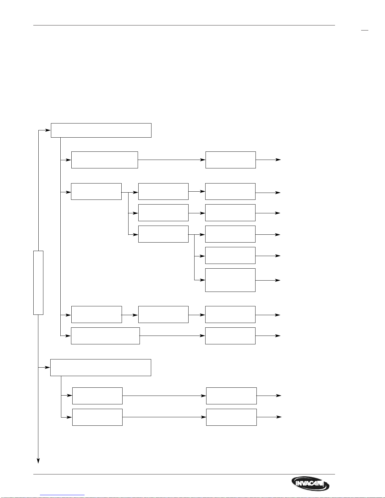
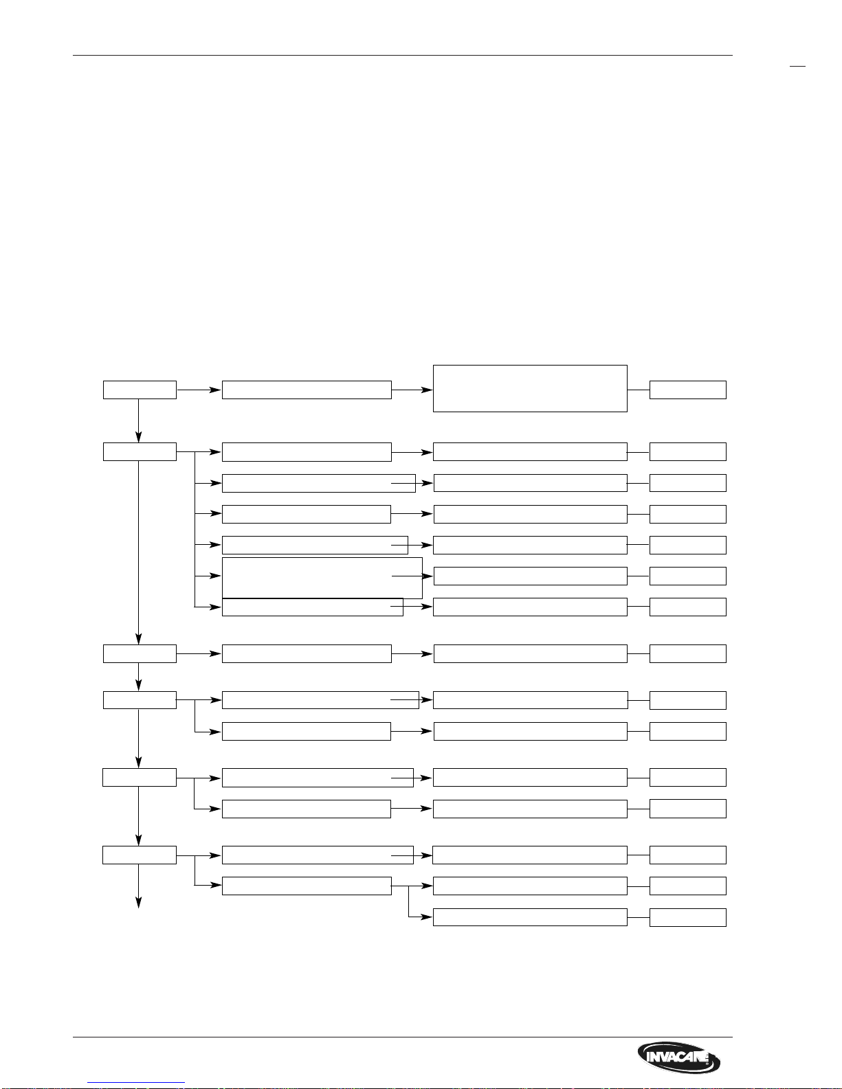
4.0 Operation troubles
4.1 General instructions
Do the following if there are any troubles in driving mode, at lighting system or power supply:
• Analyze the in 4.2 described troubleshooting.
• Check the status display at remote and analyze the error codes like in chapter 5.1.
• Do the required checks / repair work. Note the cross references in the appertaining chapters in the manual or
in the appertaining documentation.
Drive motor / steering
servo motor disengaged
Battery defective
Battery deep
discharged
Power supply
interrupted
Engage motors
Replace battery
Pre-charge battery
check overload
protector
check voltage at
remote
check voltage at
main module
Status display at
remote off
Status display at
remote flashes
Microswitch defective
(nur TÜV-Version 10 km/h)
Motor defective
Incorrect program-
ming
Check program-
ming
Replace motor
Check microswitch
Error code 1 - 12 Check error code
Wheelchair doesn´t drive
Störungen
Drive motor runs in a jerky manner
Chapter 6.0
Chapter 10.1
Chapter 10.2
not correct
Chapter 12.2
Chapter 12.1
Chapter 5
not correct
Chapter 9.1
Manual for pro-
gramming unit or
PCD-software
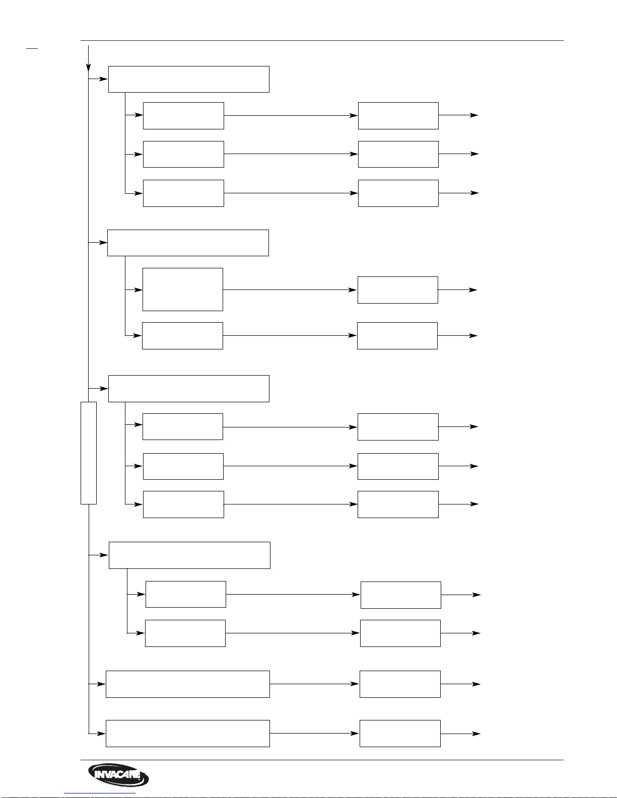
4.2 Troubleshooting
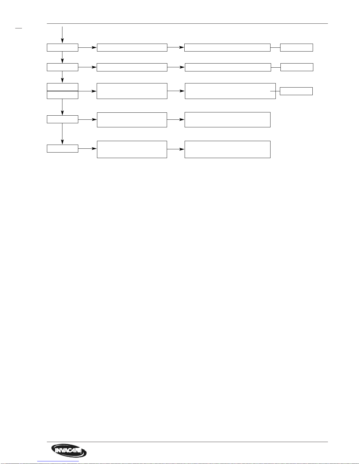
9
Remote defective Replace remote
Switch remote off
and on
Joystick not in
neutral position
when switch on
Status display flashes, after 4 sec. the
driving mode display also flashes
Chapter 12.2
Chapter 12.2
Motor defective
Incorrect program-
ming
Check program-
ming
Replace motor
Steering servo motor reacts slowly /
irregularly
Chapter 9.1
Manual for programming unit or
PCD-software
Light-/servo modu-
le defective
Replace light-
/servo module
Chapter 12.3
Cable / connector
defective
Check / replace
cable / connector
Replace light bulb
Light bulb defec-
tive
Lighting system defective
Chapterl 11.1/11.2
Chapter 11.1/11.2
Light-/servo modu-
le defective
Replace light-
/servo module
Chapter 12.3
Störungen
Charging unit
defective
Replace charging
unit
Replace battery
Battery defective
Charging batteries impossible
chapter 10.1
Chapter 10.3
Signal horn defective Replace remote
Chapter 12.2
Speedometer defective
Replace speedo-
meter
Chapter 12.4
10
5.0 Error messages at remote
5.1 Error codes of remote
The following error codes refer to the G40 standard model with remote, main module and servo-/light module.
Do the follwing check before analyzing the error codes:
• Switch on and off the remote several times.
Wait five sec. before switching on again.
This check determines whether the error can automatically be corrected by the electronic system in which case
the flashing of status display is automatically deactivated.
If this is not the case, localize the error with the flash code.
2 x flashes
Flash codes on remote status display:
1 x flash Elektronic module defective
Steering servo disengaged
5 x flashes
Motor connection loose/defective
Drive motor defective Check/replace motor
Check/replace cable/connector
6 x flashes
Brake error at motor Check motor brake
Motor connection loose/defective Check/replace cable/connector
4 x flashes
Motor connection loose/defective Check/replace cable/connector
Drive motor defective Check/replace motor
3 x flashes
Drive motor disengaged*
Engage motor (Driving mode)
* Flash code can only be activated when you move the joystick in freewheel operation.
Check / replace status display of
modules
Cable/connector loose, defective
Servo-/light module defective
Back turn signal bulb defective **
Short circuit in Lighting system
Engage servo (Driving mode)
Check/replace connector/cable
Replace servo-/light module
Replace turn signal bulb
Check lighting system
Steering servo motor defective Check/replace servo motor
Check/replace motor
Chapter 12.0
Chapter 9.2
Chapter 13.0
Chapter 12.3
Chapter 9.2
Chapter 11.2
Chapter 11.0
Chapter 9.1
Chapter 19.0
Chapter 9.1
Chapter 13.0
Chapter 9.1
Chapter 9.1
Chapter 9.1
Chapter 9.1
** Flash code can only be activated when the turn signal is also switched on.
The flash codes can be generally deactivated by switching off and on at remote.
11
7 x flashes Battery deep discharged
9 x flashes
Incorrect data transfer bet-
ween the modules
10 x flashes
11 x flashes
Power-assisted steering- or
drive motor overloaded
Switch off and on the remote
12 x flashes
Compatibilityproblems bet-
ween the modules
8 x flashes Battery voltage too high
Chapter 10.2
Charge batteries
Chapter 10.3
Check charging unit
Check modules and Programming,
inform INVACARE-service
Chapter 14.0
Repair by INVACARE-service
necessary
12
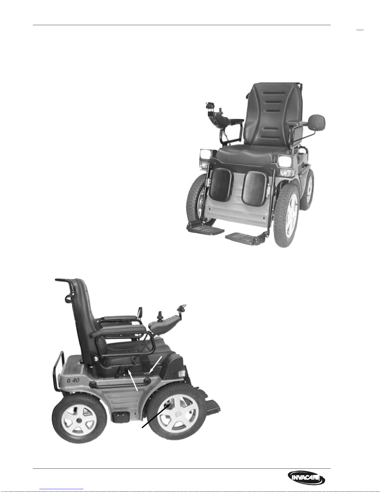
6.0 Arrangement of assemblies, components and features
G40, front view
G40, side view
1 Leg rests complete, appertaining to seat
system
2 Chassiscovering
3 Seat shell, appertaining to seat system
4 Seat padding, appertaining to seat system
5 Back padding, appertaining to seat system
6 Mirror
7 Front lighting system, integrated in
seat shell
8 Front wheels, powered
9 Back wheel, steerable
10 Frame with back shell 11 and grip
grip 12
13 Sides complete with arm rests
14 Side grip
15 Covering
16 Remote with speedometer
17 Hand brake complete with brake
disc 18
19 Back rest adjusting, complete
20 Walking stick holder
21 Walking stick loop
The following illustrations show the arrangement of the main assemblies, components and features for righthanded people. The terms are the same as the component terms in the replacement parts catalog.
3
4
5
6
1
1
7
7
2
8
8
9
2
8
9
11
13
14
15
16
17
18
19
20
12
10
21
 Loading...