

Invacare EC-Track Installation & Technical Description

Invacare® EC-Track®
Installation & Technical Description,
Installation og teknisk beskrivelse,
Installation et description technique,
Montering og teknisk beskrivelse,
Montering och teknisk beskrivning
enRailsystemforceilinghoistRobin®/Robin
Mover®
ServiceManual................................3
daSkinnesystemtilRobin®/RobinMover®
løftemotor
Servicemanual.................................29
frSystèmederailspourlève-personnesurrail
Robin®/RobinMover®
Manueldemaintenance........................55
SkinnesystemfortakmontertRobin®-/Robin
no
Mover®-løfter
Servicehåndbok................................83
svSkensystemförtaklyftenRobin®/RobinMover®
Servicemanual.................................109
PROVIDER:Keepthismanual.
TheproceduresinthismanualMUSTbeperformedbyaqualied
technician.

©2019InvacareCorporation
Allrightsreserved.Republication,duplicationormodicationinwholeorinpartisprohibitedwithoutpriorwritten
permissionfromInvacare.Trademarksareidentiedby™and®.AlltrademarksareownedbyorlicensedtoInvacare
Corporationoritssubsidiariesunlessotherwisenoted.

Contents
1General.........................................4
1.1Aboutthismanual..............................4
1.2GeneralSafety.................................4
1.3WarrantyInformation...........................4
2Railsystem......................................5
2.1Singlerailsystem..............................5
2.2Traversesystem................................6
2.3RoomTransfer.................................7
2.4Rails,Brackets&Accessories......................8
3Installation.......................................14
3.1GeneralInstallationInstructions....................14
3.2CeilingMountingSystem.........................14
3.2.1ConcreteCeiling.............................14
3.2.2ConcreteCeilingwithSuspendedCeiling...........15
3.2.3WoodenCeiling.............................17
3.3Wallinstallation–endhungrail...................18
3.3.1RailproleMandL..........................18
3.4Wallinstallation–sidehungbracketorside/endhung
bracket.....................................19
3.5Curves......................................19
3.6Railcoupling..................................20
3.6.1RailcouplingforproleMandL................20
3.6.2RailcouplingforproleS......................20
3.7Wallsupportlegs..............................20
3.8Mountingtraversesystem........................21
3.9Installationoftrackswitches......................22
3.10Transitcoupling...............................22
3.10.1Adjustingtheholeinthewall/dooropening.......22
3.10.2Installingthetransitcoupling..................23
3.10.3Installingandconnectingcontrolbuttonand
3.10.4Installingatraversesystemwithlockxturefor
3.10.5Installationofasinglerailforacouplingsystem....24
3.10.6Mountingthepositioningxturesonparallelrail
3.11Installingtheceilinghoisttotherailsystem..........25
3.11.1InstallingRobin®............................25
3.11.2InstallingRobin®Mover......................26
3.12Inspection/checkoftherailsystem...............26
4T echnicalData....................................28
4.1Therailsystem................................28
4.2Dimensionsfordifferenttrackinstallations............28
powersupply..............................24
transitcoupling.............................24
S-proleandM/L-proles.....................24
Invacare®EC-Track®
1General
1.1Aboutthismanual
Thisinstallationmanualisintendedasaninstructionwhen
planningandcarryingouttheinstallation.Inorderto
ensuresafetywhenhandlingtheproduct,readthemanual
carefullyandfollowthesafetyinstructions.
Forpre-saleanduserinformation,pleaseseetheuser
manual.FindtheusermanualonInvacare’swebsiteor
contactyourInvacarerepresentative(seeaddressesatthe
endofthismanual).
Symbolsinthismanual
Inthismanual,hazardsareindicatedbysymbols.The
symbolsareaccompaniedbyasignalwordthatindicates
theseverityoftherisk.
WARNING
Indicatesahazardoussituationthatcould
resultinseriousinjuryordeathifitisnot
avoided.
CAUTION
Indicatesahazardoussituationthatcould
resultinminororslightinjuryifitisnot
avoided.
IMPORTANT
Indicatesahazardoussituationthatcould
resultindamagetopropertyifitisnot
avoided.
TipsandRecommendations
Givesusefultips,recommendationsand
informationforefcient,trouble-freeuse.
1.2GeneralSafety
WARNING!
Safetyrulesbeforeinstallation
–Allinstallationsmustcomplywiththenational
rulesandstandards.
–Useonlyapprovedinstallationcomponents.
–Ateverypointofsuspension,theroof/ceiling
structuremustbeabletowithstandastatic
loadofatleast300kg.
–Beforemountingarailsystem,theroof,
walls,andoormustbeexaminedcarefully.
Determinetheexactmaterialsinvolvedinthe
roofandwalls.Thisexaminationmustonly
becarriedoutbyasuitablyqualiedperson.
–Therailsystemmustbemountedonlyby
suitablyqualiedpersons.
StressT est
InaccordancewiththeEuropeanstandardEN10535,the
systemshallbestresstestedwith300kg.Thisshouldbe
doneateachxingpoint.Thistestistobecarriedout
asatestingofthesubstratum’sabilitytokeeptherail
systeminplace.Thistestshallbecarriedoutbyasuitably
qualiedperson.
1.3WarrantyInformation
Termsandconditionsofthewarrantyarepartofthe
generaltermsandconditionsparticulartotheindividual
countriesinwhichthisproductissold.
ContactinformationforyourlocalInvacareofceislocated
insidethebackcoverofthismanual.
Givesinformationabouttherequiredtools.
ThisproductfeaturestheCEmark,in
compliancewiththeMedicalDevice
Regulation2017/745Class1.Thelaunchdate
ofthisproductisstatedintheCEdeclaration
ofconformity.
4
1586749-C

Railsystem
2Railsystem
2.1Singlerailsystem
Asinglerailsystemissuitedinsituationswherethelifting
isdoneatspecicorlimitedplaces(e.g.underneaththe
track).
Asinglerailsystemconsistsofonestraightrail.Thisrail
maybemountedparalleltothewallsordiagonallyinthe
room.
Therailsystemcanbeoptionallyextendedwithcurves
withanglesof30°,45°,60°and90°.
Therailsystemcanbeinstalledonthewallortheceiling.
Withasinglerailsystemitispossibletohidethe
installationintheceilingsothatonlytheopeningofthe
railisvisible.
1586749-C5

Invacare®EC-Track®
2.2Traversesystem
Atraversesystemissuitedforcaseswhenanunlimitednumberofliftingplacesisrequiredintheroom.
Atraversesystemconsistsoftwoparallelrailsmountedontheceilingorthewall.Ineachparallelrail,atraversetrolleyis
insertedwitchcantravelthefulllengthoftheparallelrails,fromendstoptoendstop.
Acrosstheparallelrailsatraverserailismountedtothetwotraversetrolleys.Thisinstallationcanbecarriedoutin
differentways,asshownintheillustrationsbelow.Withahoisttrolleyinsertedinthetraverserail,thehoistcantravel
thefulllengthofthetraverserail.
Thesystempermitsanunlimitednumberofliftingplaces,sincethetraversesystemcoverstheentireroom.
Combinationsoftraversesystems
RailsCombinationPossiblecombinations
Parallel:S-Prole
Traverse:S-Prole
Under-hungtraverse:
Between-hungtraverse:
Parallel:S-Prole
Traverse:M-Prole
Parallel:S-Prole
Traverse:L-Prole
Parallel:M-Prole
Traverse:M-Prole
Under-hungtraverse:
Partlybetween-hung
traverse:
Under-hungtraverse:
Under-hungtraverse:
Between-hungtraverse:
Partlybetween-hung
traverse:
Parallel:M-Prole
Under-hungtraverse:
Traverse:L-Prole
61586749-C
RailsCombinationPossiblecombinations
Parallel:L-Prole
Under-hungtraverse:
Traverse:L-Prole
Between-hungtraverse:
Partlybetween-hung
traverse:
Railsystem
2.3RoomTransfer
Roomtransferwithtwohoists
RoomtransfercanbedonebyusingtwoRobinhoists;
oneineachroom.T oeasethisoperation,anInvacare
room-to-roomtrolleyisused.
Roomtransferispossibleinbothsingle-orroomcovering
installations.Itisimportantthattherailsarelocated
asclosetothedoorwayaspossible.Wheninstallinga
roomcoveringrailsystemintendedforroomtransfer,
thetraverserailmustbeinstalledperpendiculartothe
wallwiththedoorway.Thedistancebetweenthetwo
endstopbuffersmustnotexceed600mm.Toobtainthe
bestpossibleresultduringroomtransfer ,theremustbea
minimumdistanceof1.85mbetweentheoorandthe
undersideofthehoist.Thismustbekeptinmindduring
installationoftherailsystem.
Roomtransferwithtransit(transitcoupling)
Asanalternativetheroomtransfercanbeachievedby
aninstalledtransitcoupling.
Thecouplingcanbeusedtoconnecteithertwotraverse
systemsoronetraversesystemandonesinglerailsystem.
Thecouplingisoperatedelectricallybyacontrolbutton
mountedonthewall.Thecouplingisdeliveredwitha
standardlengthof800mm.
Forfurtherinformationseechapters2.4Rails,Brackets&
Accessories,page8and3.10Transitcoupling,page22.
1586749-C
7
Invacare®EC-Track®
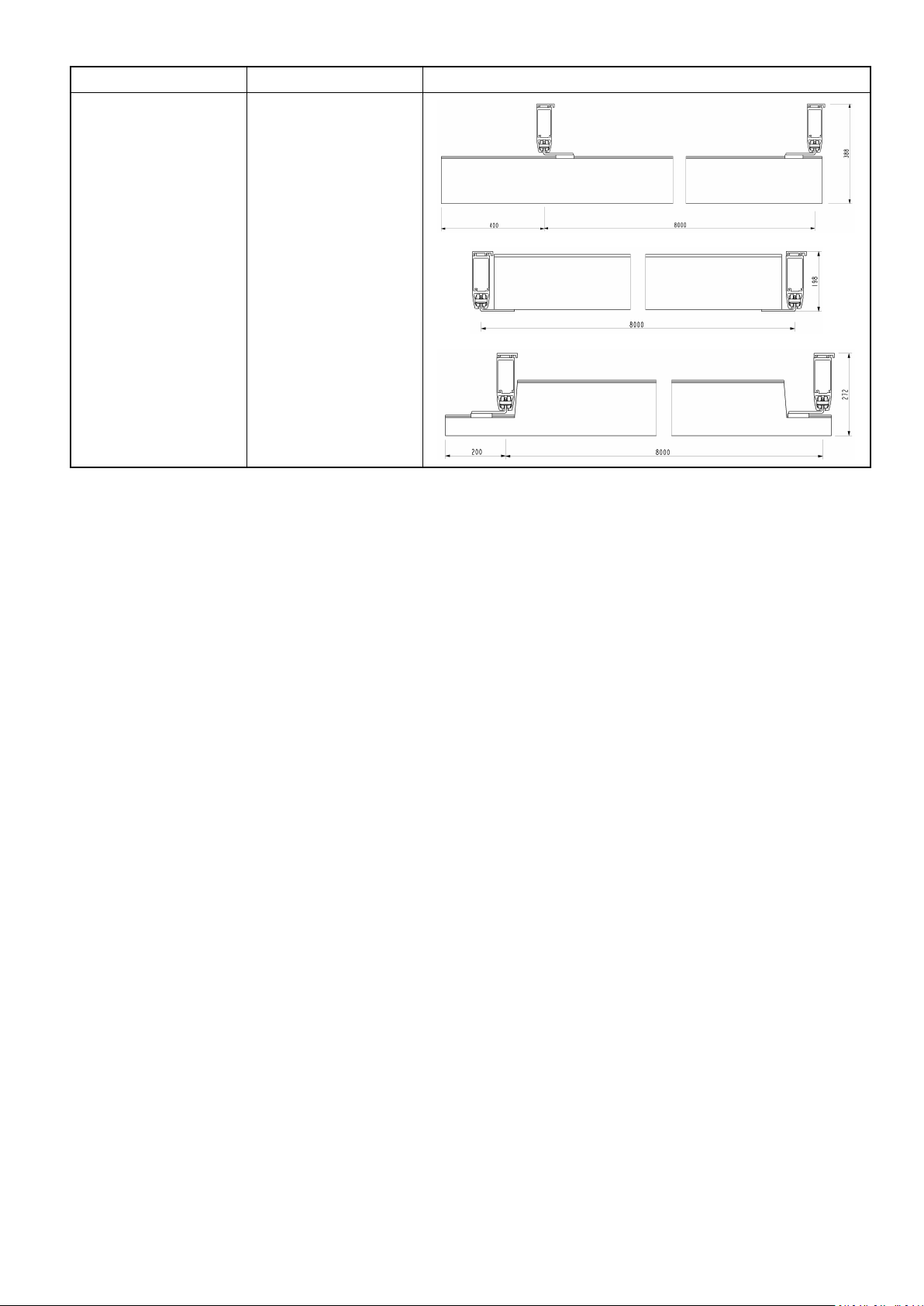
2.4Rails,Brackets&Accessories
RailprolesS,M,L
Type
Description
RailproleSMax.length=7.8m
Max.spanwithoutsupport:
2m
RailproleMMax.length=7.8m
Max.spanwithoutsupport:
4m
RailproleLMax.length=7.8m
Max.spanwithoutsupport:
8m
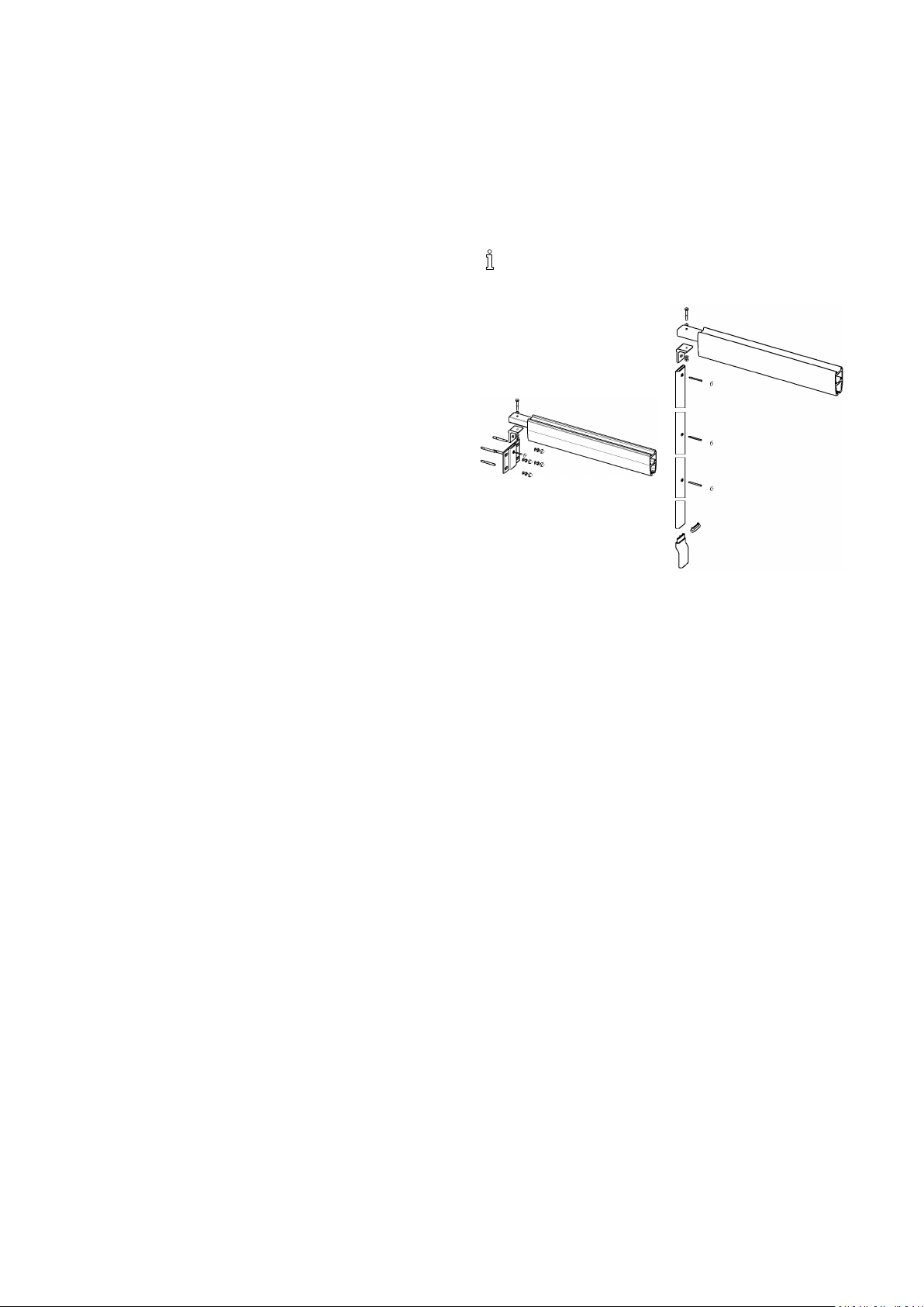
Curves30°,45°,60°,90°
Type
Curve30°
Description
RailproleSwithcurve30°
and2x200mmstraightrail
Curve45°
RailproleSwithcurve45°
and2x200mmstraightrail
Curve60°
RailproleSwithcurve60°
and2x200mmstraightrail
Curve90°
RailproleSwithcurve90°
and2x600mmstraightrail
Info
color:white
Info
Allcurveshavearadiusof
400mm.
Allcurvesaresupplied
asrightorleftcurves.
Characteristicsforrightand
left,seechapter3.5Curves,
page19
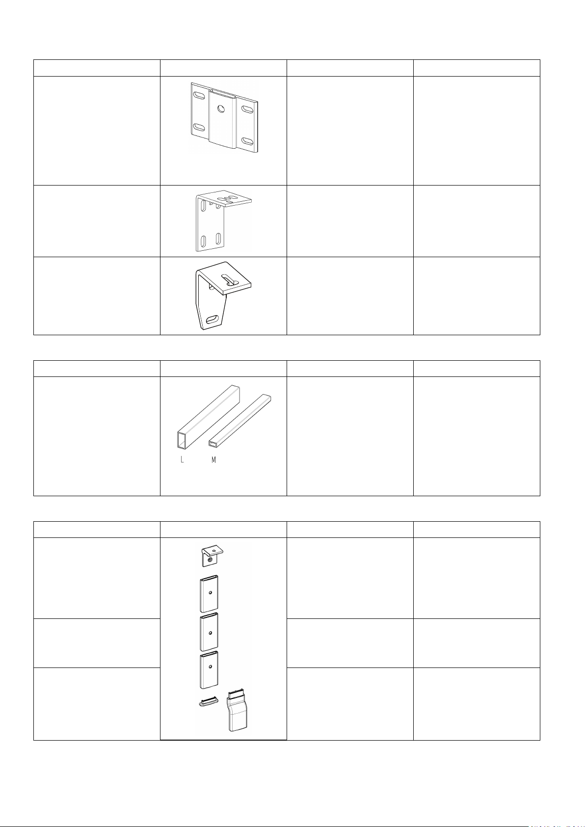
Ceilingbrackets
Type
Description
Ceilingbracket,QuickCeilingbracketswithhidden
xingparts.T obeused
forceilinginstallationof
single-railandtraverse
systems.
Sizes(WxDxH):
•30x68x14mm
(forcurves)
•70x68x14mm
(forordinaryceiling
supension)
•120x68x14mm
(forrailcoupling)
Ceilingbracket,Quick,
Traverse
Bracketsfortraverse
systemandsidehung
wallinstallation
Thebracketismounted
beneaththetraversetrolley ,
attheunderhungandpartly
between-hungtraverse
assembly.
Info
Installation:Seechapter3.2
CeilingMountingSystem,
page14.
81586749-C
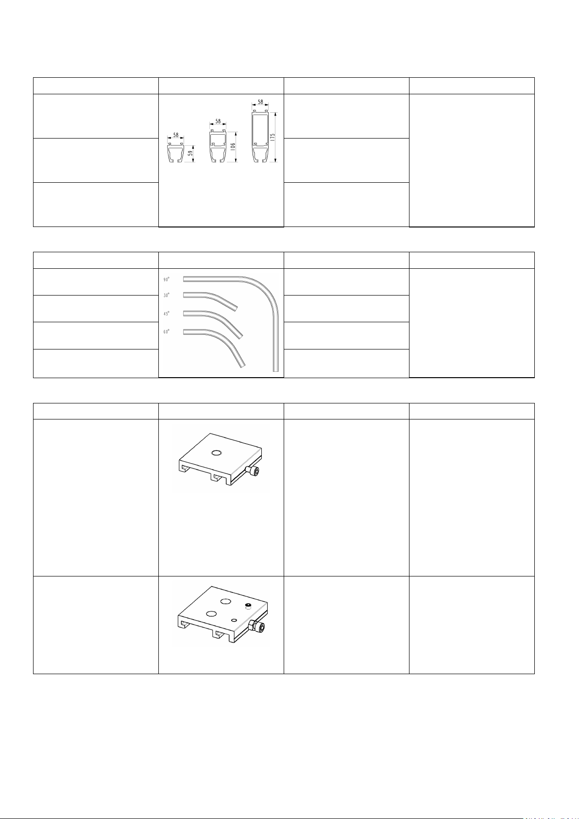
Railsystem
Type
Description
Ceilingbracket,StandardCeilingbracketswithvisible
xingparts
Tobeusedforceiling
installationofsingle-railand
traversesystems.
Sizes(WxDxH):
•30x146x14mm(for
curves)
•70x146x14mm(for
ordinaryceiling
supension)
•120x146x14mm(for
railcoupling)
Standardceilingbracketwith
lock
Ceilingbracketwithlock
screwmeasuring(70x146).
Usedforceilinginstallation,
withmin.1perstraight
rail.Thisensuresthatthe
railisnotdisplacedafter
installation.
Sizes(WxDxH):
•70x146x14mm
Info
Shims
Type
Shimforstandardceiling
bracket
Description
Availableforceilingbrackets
in30,70,120mmwidth.
Height:
•1mm
•3mm
•5mm
Info
Shimsaretobeusedin
installationstocompensate
possibledifferencesofthe
heightintheroof/ceiling
structure.
1586749-C9
Invacare®EC-Track®
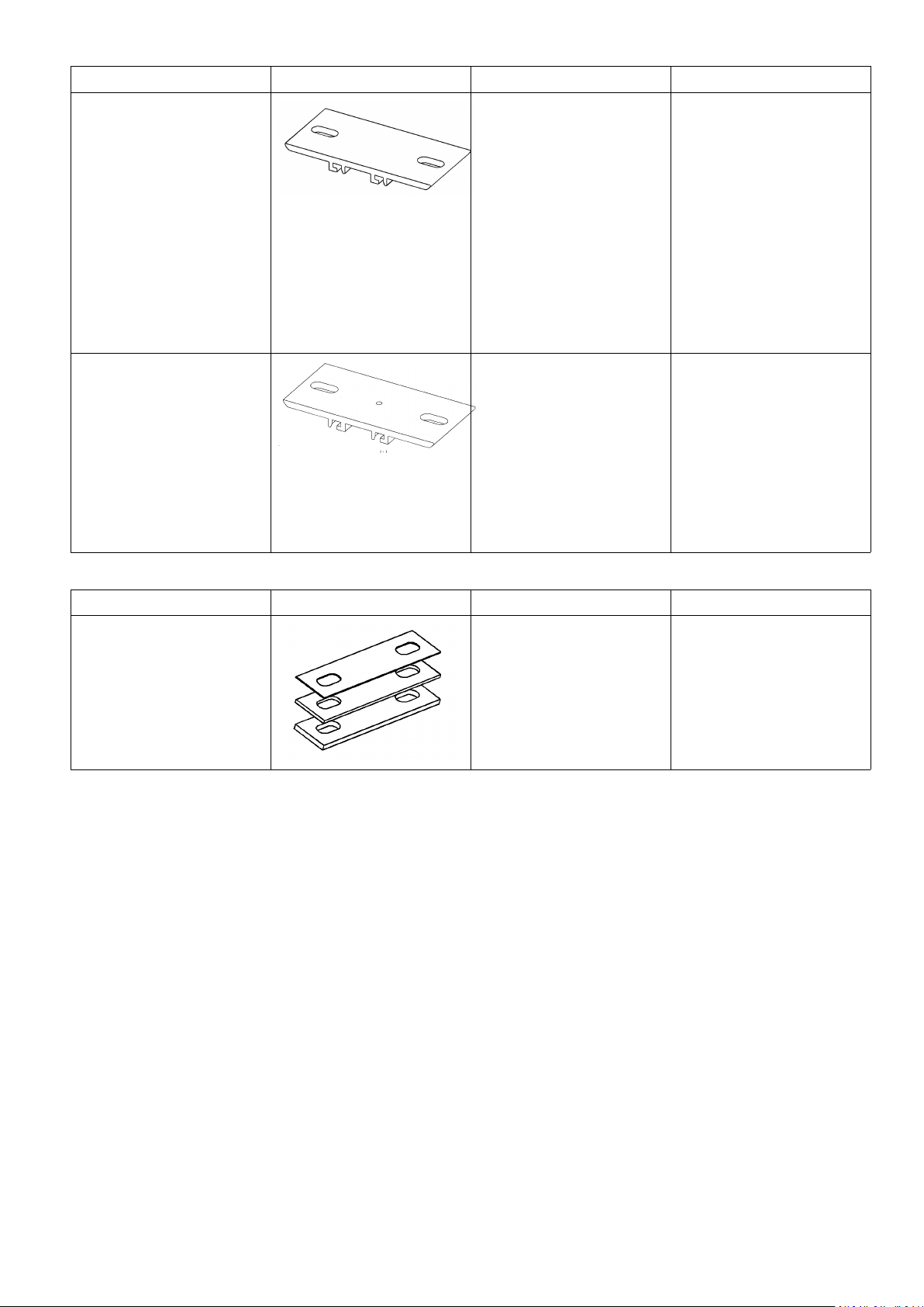
Wallbrackets
Type
Description
Wallbracket,endhungTobeusedwheninstalling
trackstoawall.Theycanbe
usedwhenthewallshave
sufcientlyhighcarrying
capacitywhenmounting
straightanddiagonallytoa
wall.
Tobeusedwithinserttubes
andconsole.
Wallbrackets,sidehungTobeusedwheninstalling
trackssidehung.Canbe
appliedifthewallhas
sufcientstrength.
Wallbracket,sideandend
hung
Tobeusedwheninstalling
trackseithersideorend
hung.Canbeappliedifthe
wallhassufcientstrength.
Inserttubes
Info
Installation:Seechapter3.3
Wallinstallation–endhung
rail,page18.
Installation:Seechapter3.4
Wallinstallation–sidehung
bracketorside/endhung
bracket,page19
Installation:Seechapter3.4
Wallinstallation–sidehung
bracketorside/endhung
bracket,page19
Type
InserttubeforrailproleM
orL
Description
Tobeusedwhenmounting
railendhungtowall,when
couplingtworails,orwhen
mountingrailsdiagonallyin
aroom.
•Inserttubeforrail
proleM:Length800
mm.
•Inserttubeforrail
proleL:Length1m.
Wallsupportleg,consoleandwallsupportfoot
Type
Description
WallsupportlegTobeusedifthewalldoes
nothavesufcientcarrying
capacitywhenmountingthe
railtothewall.Maybeused
forthemonorailsystemsas
wellasthetraversesystems.
Leglength:2.6m/3m
WallsupportconsoleTheconsoleisalsoused
togetherwiththeendhung
wallbracketwhenmounting
straightordiagonal.
WallsupportfootLowfootforroomswithout
skirtingboard
Info
Inserttubeissupplied
dependingontheparticular
mountingsituation.
Info
Installation:Seechapter3.7
Wallsupportlegs,page20
Highfootforroomswith
skirtingboardpanalongthe
oor
101586749-C
EndStop
Railsystem
Type
Description
Info
Endstop Theendstopismounted
atallrailoutlets,which
ensuresthatthetrolleysdo
notleavetherailsystem.
Whentheendstopis
mounted,therubberplugis
tofacetowardsthetrolley.
endstopfortraverserail Whenthetraversesystemis
between-hung,thetraverse
railsendstopistobe
mountedinthetraverse
trolley.
Whentherailsaremounted
toawall,theendstopisto
beplacedsofarintotherail
thatthehoistdoesnothit
thewall
Insomecountries/localareasthereisademandfordoublesecuringoftheendstops.Suchextrasecuringcanbe
achievedbyinstallingoneofthefollowing:
•M5x16mmthreadformingscrew(e.g.Bufab/SweboltMRXorequal),10mmfromeachendoftherail,25mm
fromtherailunderside(thescrewcanbeinstalledinapre-drilledholeØ4,3mm).
•Ø6,3x22mmthreadformingscrew(e.g.Bufab/SweboltR6Borequal),10mmfromeachendoftherail,18
mmfromtherailunderside.
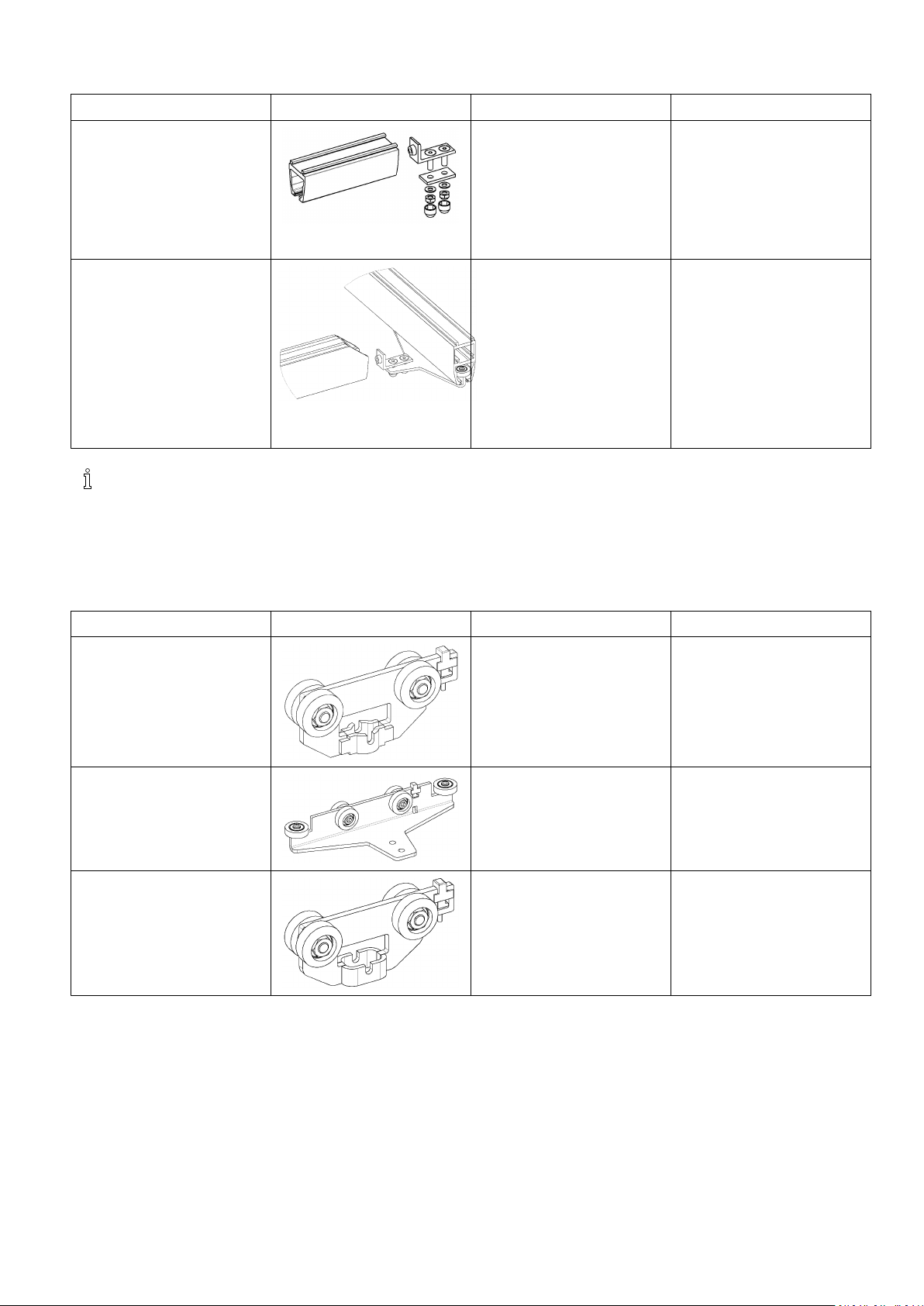
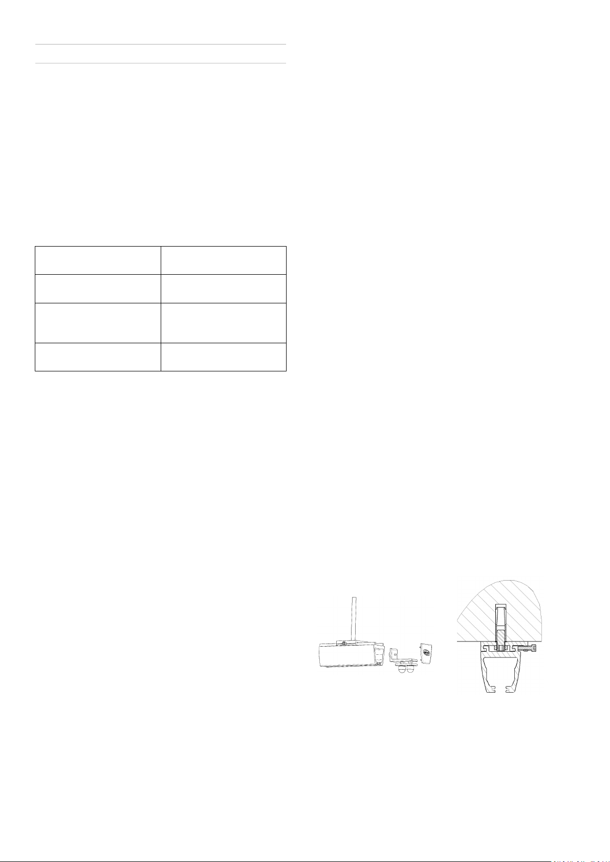
Trolleys
Type
HoistTrolley
Description
The hoist trolley is used for
individual mono rail systems
as well as traverse systems.
The hoist trolley is used
when a Robin ceiling hoist is
to be mounted in the track
system.
TraverseTrolley Thetraversetrolleyisused
whenmountingatraverse
system.Foratraverse
system,2traversetrolleys
arealwaysused.
Room-To-RoomTrolley Theroom-to-roomtrolleyis
usedwhenatransferfrom
oneroomtoanotheris
required,typicallythrougha
doorway.
Info
1586749-C
11
Invacare®EC-Track®
RailEndPlugs
Type
Description
RailendplugS,M,LRailendplugsaresupplied
forrailprolesof3sizes.
Color:white.
Tobeusedattheclosureof
bothendsofallrails.
Mounting:Pressintotherail
proleaftertherailsystem
ismounted.
Pendles
Type
Description
Pendles,adjustablePendlesareappliedifthere
isaneedforinstallinga
lowerrailsystemthanthe
originalceilinglevel.Canbe
usedinhiddeninstallationas
wellasvisibleinstallations.
Sizes(adjustablelength):
•200–300mm
•280–460mm
•440–740mm
Info
Info
Installation:See3.2.2
ConcreteCeilingwith
SuspendedCeiling,page15.
TrackSwitch
Type
Description
Trackswitch,manualThetrackswitchismanually
operatedandisinstalled
withastandardceiling
bracket.Thetrackswitchis
usedincombinationwitha
ceilinginstalledsinglerail
systemwithS-prole,where
achangeindirectionis
requiredduringmovement
ofthepatient.
TransitCoupling
Type
Description
TransitcouplingThetransitcouplingis
operatedelectricallyand
mountedwithpendlesin
theceilingonbothsidesof
thewall.Length:800mm.
Thecouplingisusedfor
movementofapatientfrom
oneroomtoanother .
•intraversesystemswith
S-,M,-andL-rails.
Info
Installation:Seechapter3.9
Installationoftrackswitches,
page22
Info
Controlbutton(forthe
wall),andatransformerare
enclosedwhendelivered.
Installation:Seechapter3.6
Railcoupling,page20
12
1586749-C
Railsystem
Type
Lockxturefortraverse
proleS
Lockxturefortraverse
proleM/L
Positioningxturesfor
parallelrailS-prole
Description
•inasinglerailsystem
withonlyS-prolerails.
Tobemountedonthe
traverseproleinthe
endthatiscoupled.Itis
mountedtoensurethatthe
traverserailandcoupling
arelockedandconnected
correctlybeforeroom
transfercanbedone.
Tobemountedonthe
traverseproleinthe
endthatiscoupled.Itis
mountedtoensurethatthe
traverserailandcoupling
arelockedandconnected
correctlybeforeroom
transfercanbecarriedout.
Tobemountedonthe
parallelrail,closetothe
coupling,topositionthe
traverserailcorrectlyin
proportiontothecoupling.
Info
Positioningxturesfor
parallelrailM/L-prole
Tobemountedonthe
parallelrail,closetothe
coupling,topositionthe
traverserailcorrectlyin
proportiontothecoupling.
1586749-C13
Invacare®EC-Track®
3Installation
3.1GeneralInstallationInstructions
Beforeinstallingarailsystem,acarefulandaccurate
measuringoftheroomisessential.Itisequallyimportant
todeterminetheconditionoftheceiling,thewallsand
theoorinordertodecidewhethertomounttherailson
theceilingoronthewalls.Next,youneedtodecidehow
manyliftingplacesareneededintheroom.
Whendeningtheliftingplaces,anindividualassessment
isrequired,whichtakesintoconsiderationthebuildofthe
individualuserandnumberofnurses.
Thefollowingplacementoftypicalliftingplacesmaybe
usedasarecommendedguideline:
Bed1mfrominsideofthebed
headend
Toilet150mmfromthefront
edge
Bathtub
Changingtable1mfromtheheadendof
1/3wayup(sitting
position),½wayup
(recliningposition)
thetable
Wheninstallingrailswithbracketsdirectlyontheceiling,
makesurethattheceilingisevenandhorizontal.(Shims
ofrespectively1mm,3mmand5mmthickness,maybe
usedtoleveloutanyunevenness.)
Keyholefortheinstallationpoint
AnyEC-Tracksystemmustbepreparedwithaninstallation
pointforthehoist.
Thisinstallationpointappearsasa32mmroundmilled
grooveonthebottomoftherailinwhichthehoististo
beinstalled.Thismilledgrooveiscalledkeyhole.
Wheninstallingtherailsystem,itiscrucialthatthis
installationpointisplacedaccordingtotheinstructions
below.
1.Generally,thekeyholemustalwaysbeplacedasclose
aspossibletotheendofarail.However,itmustbe
atleast250mmawayfromtherailend.
2.Iftherailgoesfromwalltowall,itshouldbeplaced
min.400mmfromtherailproleend.
3.Ifatraversesystemismounted,thekeyholeshould
beplacedascloseaspossibleacrosstheendofthe
rail.However,itmustbeatleast250mmawayfrom
therailend.
Ifthetraverserailcontinuesallthewayouttothe
walls,itshouldbeplacedmin.400mmfromtheend
oftherail.
Whenmeasuringfortheselectedrailsystem,takeinto
considerationasuitableparkingplaceforthehoistwhenit
isnotinuse.Asuitablespotcouldbenearawall,where
thehoistchargerismountedonthewall.
Checkthecustomizedrailaswellasthebracketsandother
accessoriesagainstthedrawing.
Checkthatanyburrsandmetalshavingshavebeen
removedfromtherailstopreventthisdebrisfromgetting
stuckinthetrolleywheelsproducingnoiseanderratic
operation.
Incaseofsinglerailsandcurvedrailsneedingcoupling,
usetheenclosedpipepins.
1.Pushthepipepinshalfwayintotheonerail.Holes
aredrilledtoØ3.2mmintherailthattheprevious
mentionedrailistobeconnectedto.Thenthenext
railisinsertedoverthepipepins.
2.Pushthenextrailintotheprotrudingpins.Donot
drillfurtherholesintherstrail.
3.Mountthebracketforrailcoupling.
When installing a traverse system where the parallel rails
are running from wall to wall, the minimum distance from
rail to wall must be 60 mm, insert the traverse trolley and
the rail end stop into the parallel rails before installation.
If not, the parallel rails must end min. 350 mm from the
wall to permit subsequently installation of the trolley.
3.2CeilingMountingSystem
3.2.1ConcreteCeiling
Whenreferringtomountinginconcreteceilings,we
differentiatebetweenmassiveconcrete(factorymoulded
concreteelements,prestressedconcretesurfaces,armored
concrete)andhollowsurfaces.
MountingwithQuickCeilingBracket
Whenusingquickceilingttings,allceilingttingsareto
bemountedintheceiling.Thentherailmaybemounted
inthese.Atleast3ceilingttingsshallbeusedperrail.
Theremustsubsequentlybemax.700mmbetweeneach
tting.Theremustbemax.200mmfromtheendofthe
railtothersttting.
When installing a mono rail system or a traverse rail in a
traverse system, it is important that the rail at one end
stops min. 160 mm from the wall to permit subsequently
installation of the hoist trolley.
At secondary installation of Robin Mover the distance
must be minimum 300 mm.
14
Measureuptoallttingsatthesametime.Itisimportant
thatthedrilledholesareonastraightline.Theprecise
markingfortheholesistobecarriedoutusinglaser
technique,chalkline,etc.
Mountinginmassiveconcreteandhollowsurfaces:
1586749-C
Installation
1.Drillholeswitha15mmhammerdrilltoadepthof
54mm.Blowholesclean.
2.InsertM12strokeanchorsintothehole(e.g.Hilti
HKD-SM12orequal).
Whenusingasettingtool(e.g.HiltiHSD-GM12x50
orequal),theanchorwillbecorrectlyfastenedinthe
concrete.
3.Mountthequickttingbyscrewingthepre-mounted
threadedrodinthestrokeanchor .
Itisimportantthatanadhesiveisusedonatting
andnutwhenthethreadedrodismountedtotting.
Inordertoensuretheachievementofmax.
strength,thethreadedrodshouldbescrewedmin.
14mmintotheanchor.
Whenusingastrokeanchorincombination
withthequickbracket,optimumaccuracyisa
requirement.Asanalternative,twocomponent
adhesivemortarforconcretecanberecommended.
Whenallttingsaremounted,pushthehoisttrolley
intotherail.Thehoisttrolleymayfacebothways.If
thetraversetrolleyistobemountedintotherail,itis
importantthatthisfacescorrectlyinconnectiontothe
followingmountingofthetraverserail.
Theendstopismountedinbothendsoftherail.Theend
stopispushedintotherailwiththerubberplugrst,and
fastenedinitiallylooselywithyourngers.
Liftuptherail,adjustthelengthofitandfastenitinto
allceilingttings.
Placetheadjustableendstopscorrectlyandtighten
appropriately.Itisimportantthattheendstopisplaced
sothatthehoistdoesnothitthewall.
Forparallelrailsinatraversesystem,itisimportantthat
theendstopisplacedsothatthetraversetrolleyshitthe
endstopatthesametime.
MountingwithStandardCeilingBracket
Theceilingbracketsarepushedontotherailand
distributedwithmax.2mbetweeneachbracketand200
mmfromthelastbracketattheendoftherail.Useat
leastthreebracketsperrail.Itisrecommendedtousean
unevennumberofbrackets,ifonlyonepersonisinstalling
therail.Thus,onebracketisplacedonthecentercreating
balancewhentherailishungintherstbolt.
Inatleastoneendoftherail,useabracketwith
lockingscrewtobesecuredtotherail.
1.Measurefortheholefortheoneexpansionboltof
thecenterbracket.
Drilltheholetoadepthofapprox.80mmwithan
8mm.impactdrillbit.Theholeisdeeperthanthe
expansionboltlengthtofacilitatedismountinglater
on.Fordismounting,youcanthendrivetheboltfully
ininsteadofpullingitout.
2.DriveanexpansionboltM8x75(e.g.HiltiHSAor
equal)in,leavingsufcientroomforthebracket
thickness(6mm),thelockingwasher(2mm)andthe
nut(7mm)plusalittleallowance.Whenyouhave
driveninthebolt,removethenutandthewasher.
3.Insertthehoisttrolleyintherail.Thetrolleycanbe
orientedinbothdirections.
4.Ifyouareinstallingthetraversetrolley,makesurethat
itiscorrectlyorientedforthesubsequentinstallation
ofthetraverserail.
5.Installendstopsatbothendsoftherail.Insertthe
adjustableendstopsintherailwiththerubberplug
siderstandthesteelplatetowardstothebottomof
therail.Fingertightenthescrews.
6.Lifttherailinplace,mountthewashersandnutsand
tightenthemlightly.Adjusttheraillengthwiseand
anglewise,andtightenthenut.
7.Drilltheholeforthebracketintheoneendofthe
railbutontheoppositesideoftherail.Drivein
theexpansionbolt,makethenaladjustmentsand
tighten.
Next,drilltheremainingholesatoneendofthe
bracketslot.Ifthedrillbithitsareinforcementbar
beforetheholeis(50mm)deep,simplydrillatthe
otherendoftheslot.Ifthedrillhitsthereinforcement
barsagain,movethebracketapprox.20-25mmalong
therail.Thebracketwillthencoverthefailedholes.
Iftheholedepthisbetween50-70mm,use
anextensionboltM8x57.
8.Driveintheremainingexpansionbolts,placethe
washersandnutsandtighten.
9.Positiontheadjustablerailstopscorrectlyandtighten.
Makesuretopositiontheendstopssothatthehoist
doesnothitthewall.
Wheninstallingparallelrailinatraversesystem,be
suretopositiontheendstopsattheexactsame
pointstoensurethatthetraversetrolleyhittheend
stopssimultaneously.
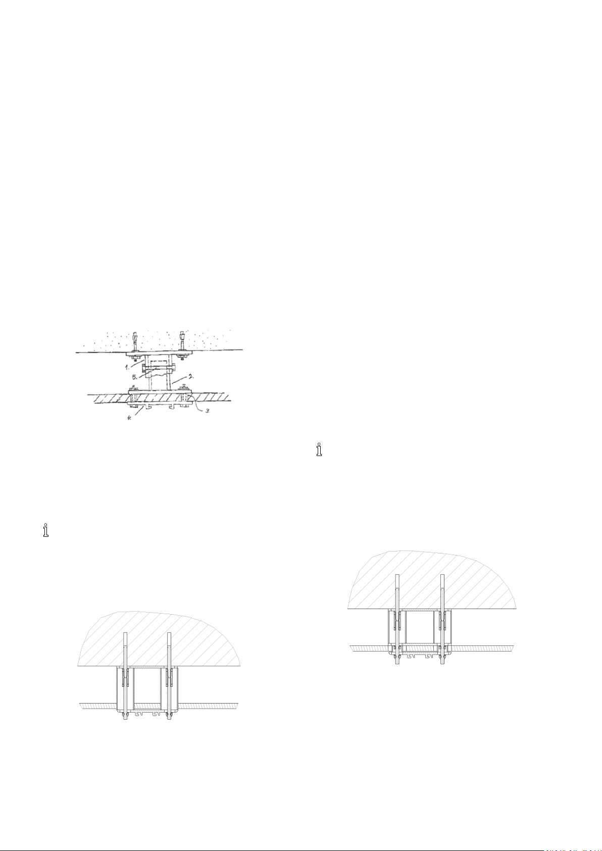
3.2.2ConcreteCeilingwithSuspendedCeiling
Forroomswithsuspendedceilingswhicharedifcultto
dismount,itisrecommendedtochooseasolutionwith
wall-mountedorwallsupportmountedrails.
Ifthefalseceilingcanbeeasilyremovedorincaseofa
newmountingofaxedsuspendedceiling,werecommend
aninstallationwithloweringbracketsforaestheticreasons.
Forthissolution,usethelowestrailproleS.
MountingwithPendlingBrackets
Inthecaseofceilingmounting,itmayoftenbenecessary
topendletheraildownward.Thisneedmayariseinthe
evenofmountinginaroomwithasuspendedceiling,
whereyouhavetopendlebetweentheoriginalceilingand
thesuspendedceiling,oriftheceilingissohighthatyou
havetopendletheraildowninordertoensurethatthe
hoist’sliftingintervalsareusedaswellaspossible.
Therearemorepossibilitieswhencarryingoutamounting
withpendles:
1586749-C15
Invacare®EC-Track®
A–Pendlingusingthreadedrodsandroundspacerpipes,
cuton-siteattheinstallationplace.Mountingbyusingthis
methodisdescribedindetailinthissection.
B–Mountingusingadjustablependles.Thispendle
consistsofanupperandlowerpart.Bypushingtheupper
partontotheoutsideofthelowerpart,theadjustable
pendlemaycoveragiveninterval.Asstandard,apendle
canbesuppliedwiththefollowingintervals:
•200–300mm
•280–460mm
•440–740mm
Whenthecorrectpendlespacinghasbeendeterminedin
connectionwiththeassembly,thependleispulledout
tothislength,andfastenedwithascrew.Thenaholeis
drilledallthewaythroughtoanM8x65bolttolockthe
pendleinthedesiredlength.
Theupperpartofthependleshouldbemountedinthe
ceilingasdescribedinchapters3.2.1ConcreteCeiling,
page14
and3.2.3WoodenCeiling,page17aswhen
mountingwithstandardbracket.
Thelowerpartofthependleshouldbeattachedtothe
nalstandardceilingtting,asshowninthesketchbelow:
•1.Pendle,upperpart
•2.Pendleunderpart
•3.Spacerpipethroughloweredceiling,Ø15
•4.Standardceilingbracket
•5.Throughlockingbolt,M8x65
Thependlemayalsobesuppliedwithpredetermined
dimensions,avoidingadjustmenton-site.
Rememberalsotoorderceilingbracketswhen
orderingpendle.
•M8lockednuts,2pcs.
•AluminiumpipesØ40,2pcs.
•Ceilingbracket(standard),1pcs.
•Removablesuspendedceiling.
•M8threadedrods,2pcs.
•Lockingwashers,2pcs.11x35x2.
(AnHKDanchorcanbeusedasanalternative,whichthe
rodsarexeddirectlyinto).
1.Togettherightlengthofthependlingbrackets,use
thedistancebetweentheconcreteceilingandthe
lowerfaceofthesuspendedceilingasyourstarting
point.
Thisdistanceisusedtodeterminethelengthofthe
pendlebracketpipeandthethreadedrod.Their
lengthmustequalthepreviouslymeasureddistance
describedabove.
2.Wheninstalling,rstinstalltheyokeforthecenter
ceilingbracket.Todothis,followtheinstructions
fortheinstallationdirectlyinaconcreteceiling.In
thiscase,however,theholesaredrilledforboth
expansionsboltsatthesametime.
3.Whendrivingintheexpansionbolts,leaveapprox.
15mmprotrudingbelowthenut,sothatyoucan
screwthecouplingnutontoittohalfitslength.
Counter-tightenthecouplingnutagainsttheexpansion
boltnut.Measurefortheholeinasuspendedceiling
anddrill/cutthisholetoØ40mm.
4.AttachanM8nutontothethreadedrod(approx.20
mmontotherod)andscrewtherodintothecoupling
nutuntilithitstheexpansionboltandcounter-tighten
thenut.
5.Aftercompletion,pushthetwoaluminiumpipesinto
theholesandfastentherailasdescribedintheusual
instructioninstructions.
Thedistancebetweenthesuspendedceilingand
theceilingbracketmustbemin.1-5mmto
preventdamagestothefalseceiling.
FixedSuspendedCeiling
Incaseofaxedsuspendedceiling,therailinstallationis
carriedoutintwosteps.Theloweringbrackettherefore
needstobesecuredwithoutthesupportfromtheceiling
bracket.
RemovableSuspendedCeiling
Incaseofaremovablesuspendedceiling,thespaceabove
thesuspendedceilingisaccessibleandpendlebrackets
andrailcanbeinstalledatthesametime.
•Concreteceiling.
•ExpansionboltsM8x75,2pcs.
•Yokes,(Steelplateforeveninstallationsurface),2
pcs.3mm.
•M8nuts,6pcs.
•Concreteceiling.
•ExpansionboltsM8x75,2pcs.
•Yoke(Steelplateforeveninstallationsurface),1pcs.
3mm.
•M8nuts,4pcs.
•M8couplingnuts,2pcs.(Collectingsleeve).
161586749-C
•M8couplingnuts,2pcs.
•M8lockingnuts,2pcs.
•AluminiumpipesØ40,2pcs.
•DistancepipesØ20(ornutsandwashers),2pcs.
•Ceilingbracket(standard),1pcs.
•Suspendedceiling.
Installation
•M8threadedrods,2pcs.
•Lockingwashers,2pcs.
(AHKDanchorcanbeusedasanalternative,whichthe
rodsarexeddirectlyinto).
1.Cutthependlebracketpipetoalengthequallingthe
distancemeasuredbetweentheconcreteceilingand
thelowerfaceofthesuspendedceilingminus50mm.
Thislengthisappropriateforadoublegypsumlayerin
theceilingandanextraallowanceof12mm.
2.Cutthethreadedrodtoalengthequallingthedistance
betweentheconcreteceilingandthelowerfaceof
thesuspendedceilingminus10mm.
3.Wheninstalling,rstinstallthetopyokeforthecenter
bracketoftherailInstalltheyokeasdescribedin
theinstallationinstructionsfordirectinstallationina
concreteceiling.Inthiscase,however,drillbothholes
fortheexpansionboltsatthesametime.
4.Whendrivingintheexpansionbolts,leaveapprox.
15mmtoprotrudingbelowthenut,sothatyou
canscrewthecouplingnutontoittoitshalflength.
Counter-tightenthecouplingnutagainsttheexpansion
boltnut.
5.Attachanutapprox.20mmontothethreadedrod
andscrewthethreadedrodintothecouplingnut,until
ittouchestheexpansionbolt,andcounter-tighten
thenut.
6.Attachthebottomyokeandsecureitwithnuts.
Avoidpaintonthebottomsectionofthe
threadedrodsuntiltheinstallationiscomplete.
7.Preparetherestoftheinstallationpointsaftera
carefulandaccuratemeasuring.
Firststepoftheinstallationisnowcompleteand
theconstructionofthesuspendedceilingcanbe
completed.
Inthenalinstallation,positionthedistancepipeinthe
suspendedceiling.Thispipewillprotectthesuspended
ceiling.Cutthedistancepipetoalengthcreatinga
distanceof1-5mmbetweenthelowerfaceofthe
suspendedceilingandtheupperfaceoftheinstallation
bracket;insteadofpipes,nutsandwasherscanbeused
toensuretherecommendeddistance.
3.2.3WoodenCeiling
CAUTION!
–Donotinstallrailstoawoodenceilingwith
tensionscrews,suchascoachscrews.
–Donotinstallrailstoawoodenceilingwith
plainwoodscrews,withouthavingperformed
ariskassessment.
QuickBracket
Itisprovidedthattheceilingtimberworkisaccessible
fromabove.Whenbeingmountedintheceilingtimber
work,exchangeshouldbeplacedasreinforcement.When
reinforcing,itisimportanttoselectexchangewoodthat
isdimensionedtotoleratethedistancebetweentwo
ceilingbeams,sosufcientcarryingcapacityisachieved.
Whenhavingmarkeduptoallceilingbracketsinthe
ceiling,youshouldexaminewhetherthereisfreespace
abovetheceilingmaterial.Whenthisisdone,holeswith
adiameterofØ12.5mmaredrilledthroughtheceiling
material.Theholesmaynowbelocalizedfromabove,
theycanbepreparedfortheexchanges,andyoumay
measurehowlongthethreadedrodsshouldbe.The
exchangeshouldcoveratleasttwoceilingbeamsoneach
sideofthesuspensionpoint.Whenusingexchanges,
two45x95mmexchangesshouldbeplacedparallelto
eachother,atadistanceof14mm,providingapassage
foranM12threadedrod.Fordeterminingthelengthof
thethreadedrod,determinetheceilingbeam’sheight+
lengthofexchangewood+ceilingmaterial+60mmfor
washerandnuts.
Placetheadaptedthreadedrodbetweentheexchange
woodandputinawasherandnutbeforethethreaded
rodisguidedfurtherdownthroughtheceilingandposition
itwithanaluminiumplate,atighteningwasherandnut
overtheexchangewood.Thealuminiumplateisscrewed
intotheexchangewoodfromthetop.Letapproximately
25mmthreadedrodprotrudedownundertheceiling
material.Aquickceilingbracketmaynowbescrewedonto
thethreadedrodbeneaththeceilingmaterial.Theceiling
bracketisfastenedwithanM12lownut.Thethreaded
rodistobescrewedentirelythroughthenut,butmust
protrudefurtherdownthatbelowthetting.
Whenmountingthebracketandnut,itisimportantto
useadhesiveonbracketaswellasnut.Whenallbrackets
aremounted,liftuptherail,adjustthelengthandsecure
it.Beforetherailisfasteneduptotheceiling,whichis
donefromabovetheceiling,itshouldbecheckedthatthe
exchangewoodisrestingonbothceilingbeams.Ifnot,
somethingshouldbeplacedbetween.
Thenutovertheexchangewoodisnowsecuredcarefully
untilthebracketliesevenlywiththeceilingmaterial.Itis
importantnottotightensomuchthattheceilingmaterial
ispulledupbetweentheceilingbeams.Whenthisis
done,asteelplateisplacedinaroundthethreadedrod
belowtheexchangewood,andthenutissecuredupinto
thesteelplate,thuslockingtheposition.
Finally,alocknutissecuredagainstthenutontheupside
oftheexchangewood.Trolleys,endstopandrailend
plugsaremountedasdescribedinsection5.2.1.
StandardBracket
Insomecases,mountingtoaceilingtimberworkmaybe
analternativetomountingtowallorwallsupport.
1586749-C
•ThreadedrodsM10,2pcs.
•M10nuts4pcs.
•Yoke1pcs.
•Braces45x90x1500mm,2pcs.
17
Invacare®EC-Track®
•Beamlayer.
•Underroof/ceiling.
•Ceilingbracket,1pcs.
•LockingnutsM10,2pcs.
•Washer,2pcs.11x35x2.
In some cases, installation with passing screws may be an
alternative to wall or wall support installation.
This requires that the roof beam layer can be accessed
from above. This is often the case in one-storied houses.
To reinforce the roof beam layer, exchanges of 45x95 mm
are placed edgeways.
Instead of the expansion bolts, a M10 threaded rod of
appropriate length is used. An installation plate (yoke
rests on top of the braces.
The exchange must rest on the roof beams on both sides
of the suspension. If this is not possible, the exchange
must be secured to prevent them from tilting when loaded.
The minimum number of three mounting points per rail
for concrete ceiling does not apply to wooden ceilings.
Here, the max. free span determines the number of
mounting points.
The rest of the installation process is similar to the process
for concrete ceilings. It is, however, necessary to drill
both holes for the center bracket (the standard bracket at
the same time.
Cut the threaded rods to appropriate length and attach
the washers and M10 nuts locking nuts.
The threaded rods are to be screwed from below and up
through the yoke. The yoke is fastened from above to the
exchanges with nails and screws.
Before the rail is fastened to the ceiling, which is done
from above, you should double-check that the exchange
wood is resting on two ceiling beams. If not, something
should be placed between.
Be careful when tightening the nuts to prevent damage to
the suspended ceiling.
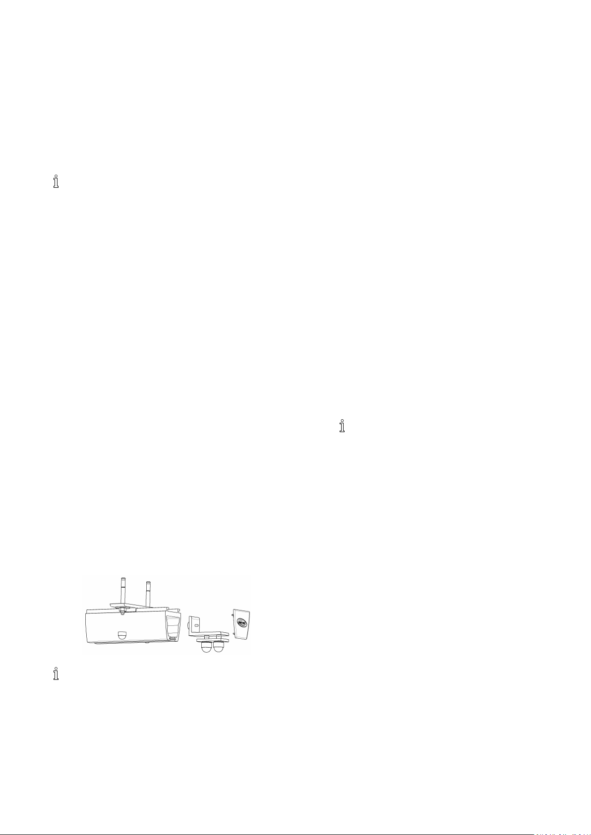
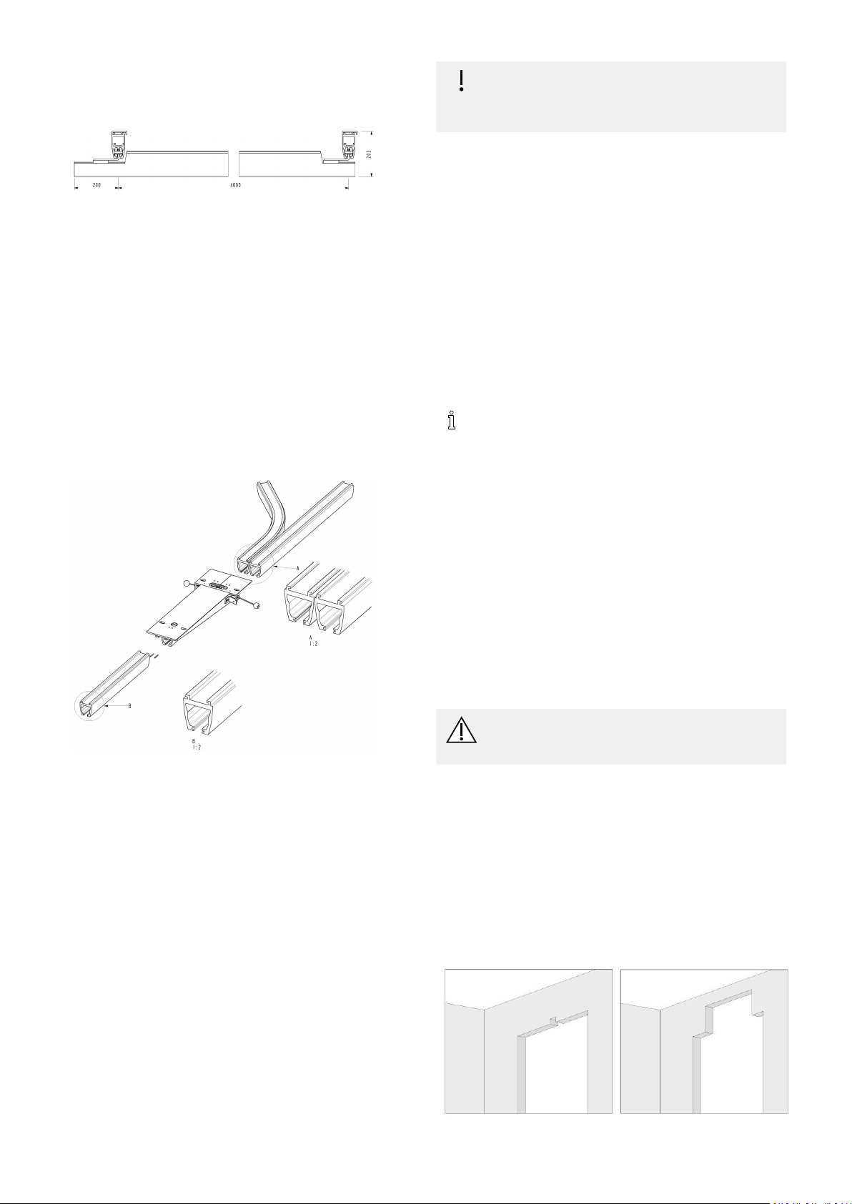
3.3 Wall installation – end hung rail
The following are recommendations only. Alternatively,
expansion bolts with the similar thickness and quality can
be applied. Always follow the recommendations from
your supplier.
For freely suspended installation, the end of the rails
may be attached to the wall with wall brackets or wall
support. Choose wall support, if you are in doubt of
the load bearing capacity of the wall material. When
installing freely suspended rails, the max. rail length must
be observed, depending on the selected rail prole. The
distance between the walls must be max. 2 m for rail
prole S , 4 m for rail p role M an d 8 m for ra il prole L.
If you need to mount or dismount a hoist trolley after
installation, the distance from one wall to the rail must
be at least 160 mm. At secondary installation of Robin
Mover, the distance must be minimum 300 mm. If you
need to mount or dismount the traverse trolley after
installation, the distance between the one wall and the rail
must be at least 350 mm. (Minimum distance from rail to
wall must always be 60 mm. If you have a wall-mounted
rail prole S , y ou c annot m ount o r d ismount t he trolley
after installation.
3.3.1RailproleMandL
Wheninstallingwallbracketsorwallsupportlegs,leavea
gapfromtheceilingtotheupperedgeofthewallbracket
oroorsupport.Thegapshouldbeatleast:
•80mmforrailproleM
•150mmforrailproleL
Whenusingwallsupportlegs,cutthesupportlegprole
toanappropriatelengthattheoorend.
Remembertomakeallowancefortheoorsupport
foot.
Incaseofskirtingboards,eitherusethehighwallsupport
foot,orcutawaytheskirtingboard.
Alwaysinstallwallsupportlegsrightatthewallintheir
fulllength.
Markforholesusingalevel,anddrilltheholes.
Concretewall
Whenmountingafreelyhangingrailintoaconcretewall,
awallbracketshouldbeusedformounting.
Formounting,werecommendusingeitherexpansionbolts
M10x68(e.g.HiltiHSAorequal),drillingdepthmin.60
mm,Ø10,oradhesivemortar(e.g.HiltiHIT-HY150and
HASM10orequal),drillingdepthmin.95mm,Ø12(when
mountedinwetrooms,usestainlesssteelHASquality
A4-70).
Brickwall
Whenmountingintobricks,ordinarywallbracketsshould
beused.However,werecommendusingoorsupportsif
thebrickwallisveryporous.
Formountingintomassivebricks,werecommendusing
adhesivemortar(e.g.HiltiHIT-HY50andHASM10or
equal),drillingdepthmin.90mmin½brickand170mm
in1/1brick,Ø12.,(whenmountedinwetrooms,use
stainlesssteelHASqualityA4-70).
Formountinginhollowbricks,werecommendusingeither
aframesheerconnector(e.g.HiltiHRDUGTorequal),
drillingdepthmin.80mm,Ø10,oradhesivemortar(e.g.
HiltiHIT-HY20,andHASM10orequal),drillingdepthmin.
95mm,Ø16.
Formountingintoporousbrickwork,werecommendusing
adhesivemortar(e.g.HiltiHIT-HY50andHASM10or
equal),drillingdepthmin.90mmin½brickand170
181586749-C
Installation
RL
mmin1/1brick,Ø12.Ifwallsupportsareusedwhen
mounting,useHASM8,drillingdepthmin.80mm,Ø10.
Lightweightconcrete
Whenmountinginlightconcrete,youmayeitherusewall
bracketsorwallsupports,dependingontheconditionof
thewall.Formounting,werecommendusingadhesive
mortar(e.g.HiltiHIT-HY50andHASM10orequal),
drillingdepthmin.90mm,Ø12(M8formountingofwall
supports).
Youmayalsousealightconcretesheerconnector(e.g.
HiltiHGN,HUD-110Lorequal),drillingdepthmin.90
mm,Ø10/HUD-18L,drillingdepthmin.80mm,Ø8.
Gypsumwall
Referalsotochapter3.7Wallsupportlegs,page20.
1.Completetheinstallationofthewallbracketorthe
wallsupportlegwithconsole,wallsupportfootand
plugsforcoveringthescrewholes.
2.Insertthehoisttrolleyorthetraversetrolleyintherail.
Thehoisttrolleycanbeorientedinbothdirections,
whereastheorientationofthetraversetrolleymust
correspondtothelayoutofthetraversesystem.
3.Insertendstopsatbothendsoftherailand
nger-tightenthematrst.
4.Inserttheinsertiontubeintherail.Theholeinthe
tubemustfaceoutwards.
5.Lifttherailwhileholdingontotheinsertiontubeto
preventitfromslidingintotherail.
6.Mounttheinsertiontubeontheconsoleatthewall
bracketorthewallsupportleg.
7.Adjusttheraillengthwisetoachievethecorrect
distancebetweenthewallandtherail.
8.Theremustbeanoverlapofatleast300mmbetween
therailandtheinsertiontube.Checktoverifyby
lookingthroughtheinspectionholeonthesideofthe
rail.Theinspectionholeislocatedexactly300mm
fromtheendoftherail
9.Whentherailisproperlypositioned,drillaØ7mm
holethroughtherailandtheinsertiontube,approx.
100mmfromtheendoftherail.Securetherailin
positionwithpassingboltsM6withlockingnuts.
10.Afterpositioningtherail,adjusttheendstoptoits
properposition.Whenpositioningtheendstop,
makesurethatthehoistwillnothitthewall.Witha
traversesystem,ensurethatthetwotraversetrolleys
hittheendstopsimultaneously.
Angular,wall-mounted
Therailcanbemounteddiagonallyintheroom.Therail
mustbeangledmax.45°.
Themountingiscarriedoutasdescribedforordinarywall
mountingwithorwithoutwallsupports.However ,the
tubeisdeliveredpreparedforangledmounting.
3.4Wallinstallation–sidehungbracket
orside/endhungbracket
Wheninstallingarailsystemsidehung,theparallelrails
canbeinstalledclosetothewall.
Wheninstallingarailsystemsidehung,thewallmusthave
suchstrength,thatwallsupportlegsareunnecessary.
WheninstallingSprole,2000mmisthemaximum
distancebetweeneachxationpoint,butatleast3points
arenecessary.
WheninstallingMprole,4000mmisthemaximum
distancebetweeneachxationpoint,butatleast3points
arenecessary.
Alwaysmeasurethedistancebetweenbothwalls
accurately,inthecorrectheightandlocationofthesystem.
Thewallbracketcanbeadjusted+/-6mm.Ifmoreis
required,useaplateof6mmbetweenbracketandwall.
Finalappearanceisinuencedbytheparallelism
betweenwallandrail.Beaccurate.
Thetraversesystemmeasurementshere,istheroomsize
measured,deducted206mm(ifbetween-hunginstalled),
and62mm(ifunder-hunginstalled).
Again,thisrequiresanaccuratemeasurementaswell
assomeconsideringoftheadjustabilityduetowall
unevenness.
Wallinstallationdependsonthestructureofthewall.
Alwaysfollowrecommendationsinchapter3.3.1Rail
proleMandL,page18.Afterinstallingthewallbrackets
andthetwoparallelrails,followinstructionsinsection3.8
Mountingtraversesystem,page21
.
3.5Curves
Followingcurvesareavailable:
•Angle30°0.2+0.2mstraightends
•Angle45°0.2+0.2mstraightends
•Angle60°0.2+0.2mstraightends
•Angle90°0.6+0.6mstraightends
Allcurveshavearadiusof400mm.
Thecurvesareavailablewithright-handbendsand
left-handbends.Itisespeciallyimportanttodistinguish
betweenrightandleftcurves,whenseveralcurvesare
includedinthesamerailsystem.
1586749-C19
Invacare®EC-Track®
•Leftcurves(L):MountingchannelsAfacingoutfrom
thecurve.
•Rightcurves(R):MountingchannelsAfacinginward
intothecurve.
Pipepinsandcouplingbracketswithlockscrewsareused
tocouplecurveswithstraightrails.
Bracketpositionsonthecurves
Angle30°0.2+0.2mstraightends:Acouplingbracketat
bothends,ifthecurveisconnectedtostraightrails.
Angle45°0.2+0.2mstraightends:Acouplingbracketat
bothends,ifthecurveisconnectedtostraightrailsanda
narrowbracketatthemiddleofthecurve.
Angle60°0.2+0.2mstraightends:Onecouplingbracket,
atbothendsifthecurveisconnectedtostraightrailsand
anarrowbracketatthemiddleofthecurve.
Angle90°0.6+0.6mstraightends:Onecouplingbracket,
ifthecurveisconnectedtostraightrailsandanarrow
bracketatthemiddleofthecurve.
Forinstallationinstructionsforcurves,seesection:5.2.1.1,
section5.2.1.2.
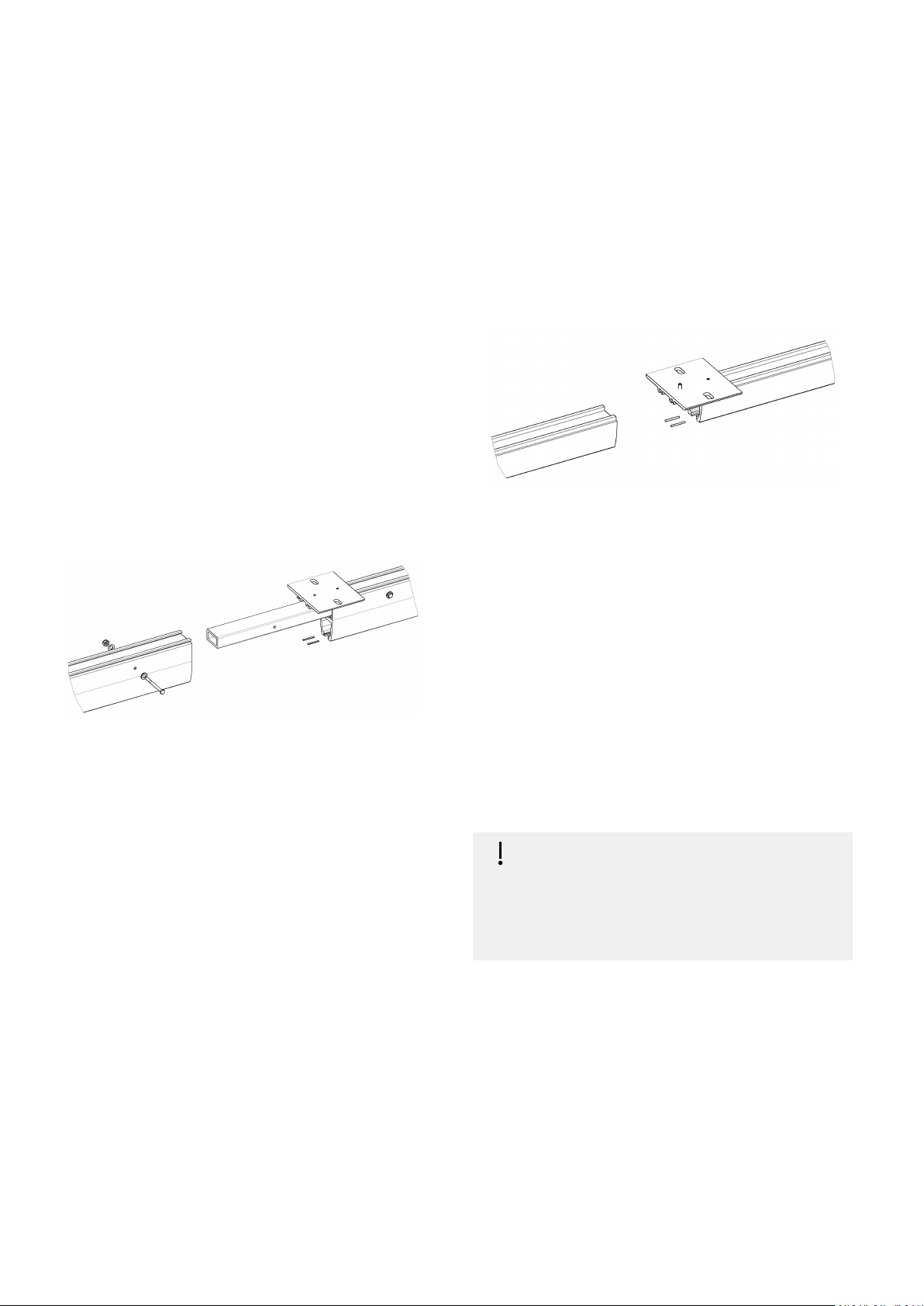
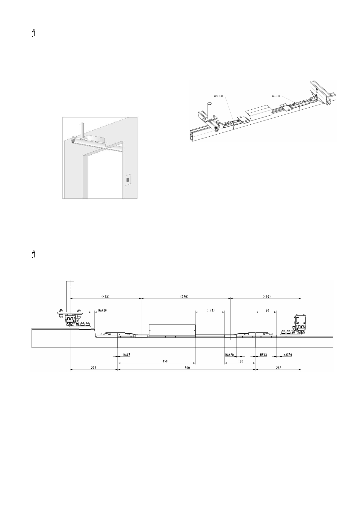
3.6Railcoupling
3.6.1RailcouplingforproleMandL
Thefollowingitemsareusedforrailcoupling:
•RailproleMno.1.
•RailproleMno.2.
•Insertiontube(forproleM).
•Couplingbracket(quickorstandard).
•Pipepins.
•Stopscrews.
•BoltM6.
•Washer.
•M6locknuts.
Pushtheinsertiontubehalfwayintorailproleno.1and
secureitwithapassingbolt.Furthermore,drilltheholes
forthepipepinsinrailproleno.2upto3.2mmina
depthcorrespondingtohalfthelengthofthepipepins.
Guidethepipepinshalfwayintorailproleno.1and
squeezethemtogetherintheend.
Pushthecouplingbrackethalfwayontorailproleno.1
andsecureitwiththestopscrew.
Thecouplingbracketisonlyrequiredwhenmountingthe
railontheceiling.Ifyouarecouplingatraverserail,the
couplingbracketisnotrequired.Pushtogetherrailprole
no.2andno.1andsecurethemwiththelockingscrew
inthecouplingbracketandthepassingbolt.
Installthecoupledrailusingtheinstructionsforinstallation
ofstraightrailproles,seesection5.2.
Whencouplinglongrails,itcanbedifculttoliftthe
coupledrailinonepiece.Inthiscase,rstinstalltherst
railontheceiling.Thenliftupthenextrailwhichhas
beenpreparedforcouplingandpushtherailstogether .
3.6.2RailcouplingforproleS
Thefollowingitemsareusedforrailcoupling:
•Railproleno.1
•Railproleno.2
•Couplingbracket(quickorstandard)
•Pipepins
•Stopscrews
1.Drilltheholesforthepipepinsinrailproleno.2up
to3.2mminadepthcorrespondingtohalfthelength
ofthepipepins.
2.Drivethepipepinshalfwayintorailproleno.1and
squeezethemtogetherintheend.
3.Pushthecouplingbrackethalfwayontorailproleno.
1andsecureitwiththestopscrew.
4.Insertrailproleno.2intothecouplingbracketand
drivethetworailstogether.
5.Tightenthestopscrewonrailproleno.2.
6.Installthecoupledrailsusingtheinstructionsfor
installationofstraightrailproles.
IMPORTANT!
Whencouplinglongrails,itcanbedifcultto
liftupthecoupledrailinonepiece.
–Inthiscase,rstinstalltherstrailonthe
ceiling.Thenliftthenextrailwhichhasbeen
preparedforcouplingandpushtherails
together.
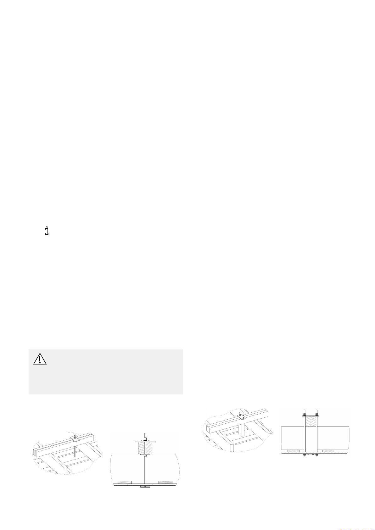
3.7Wallsupportlegs
Wallsupportlegsareusedforinstallationongypsumwalls
andwallsofotherlightweightplatematerial.
201586749-C
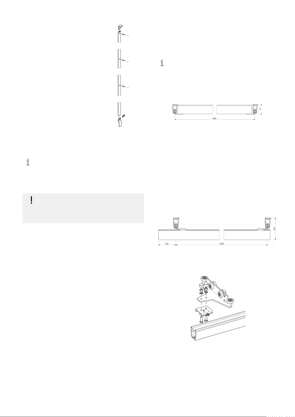
Installation
•Wallsupportlegprole(adjust
length).
•Supportconsole.
•Wallsupportfoot.
•Plasticcoverplugs.
•ScrewsM6.
Thewallsupportlegiscutinthe
rightlength,intheendfacing
againsttheoor.
Whenmeasuringtheprolelength,
includeaminimumdistance
betweenthetopofthebracketand
theceiling.Minimumdistanceto
beobserved:
•M-prole:min.80mm
•L-prole:min.150mm
Mountthewallsupportlegonthewallwiththreescrews.
UseØ6mmscrews.Thewallmaterialdeterminesthe
choiceofscrews.
Formountingintogypsum,werecommendusing
(e.g.HiltiHGAorequal)sheerconnectorfor
cavities(e.g.HiltiHGAorequal).
Incaseofskirtingboards,eitherusethehighwall
supportfootorcuttheskirtingboards.
IMPORTANT!
–Remembertomakeallowanceforthewall
supportfoot.
–Alwaysinstallwallsupportlegdirectlyonthe
wallintheirfulllength.
•RailproleS:max.freespan2m,max.protrusion
200mm
•RailproleM:max.freespan4m,max.protrusion
200mm
•RailproleL:max.freespan8m,max.protrusion
400mm
Whenarailismountedaspartiallybetween-hung,
itisalwaysthemax.protrusionfortheS-prole
thatisapplicable.
Whenmountingthetraverserail,therearethreepossible
methods:
Thetraverserailisbetween-hung
Themeasurementforthetraverserailisalwaysthe
distancebetweenthetwoparallelrailsminus86mm.
Whenthetraverserailismountedbetween-hung,the
hoisttrolleyisinsertedinthetraverserailandtheend
stopsareplacedlooselyatbothendsofthetraverserail.
Rememberthattherubberplugontheendstopalways
shouldfaceinwardtowardthehoisttrolley.Lifttherailon
topofthetraversetrolley,sothattheendstop’s2bolts
alignwiththetwoholesinthetraversetrolley,thensecure
itwithwashersandlocknuts.Beforetherailissecurely
fastened,itisimportantthatthedistancebetweenthe
traverserailandeachoftheparallelrailsisequalinboth
ends.Whentherailissecured,installthecoverplugson
locknutsandintherails.
Thetraverserailisunder-hung
3.8Mountingtraversesystem
Theparallelrailsaremountedinceilingorwallas
describedintheprevioussectiononthecurrentmounting
conditions.
Eitherifthetwoparallelrailsaremountedusingquick
orstandardttings,itisimportantthatanydeviationof
parallelismofthetworailsdoesnotexceed+/-2mm.
Whenmountingparallelrails,itisimportanttotakeinto
accountwhetheritmustbepossibletoinsertatraverse
trolleylateronornot.Ifnot,therailsmayrunallthe
wayouttothewall(minimumdistancefromrailtowall
mustalwaysbe60mm).Inthiscaseitisimportantthat
thetraversetrolleyandendstoparepushedintothe
railbeforetherailismounted.However,ifitshouldbe
possibletoinsertthetrolleylateron,itisimportantthat
thereisaminimumdistancebetweentheoneendofthe
railandthewallof350mm.
Rememberthattheendstopintheparallelrailsistobe
placedsothatthetwotraversetrolleyshittheendstops
simultaneously.
Thedistancebetweentwoparallelrailsisalwaysmeasured
fromcentertocenterofthetworails.
Generally,thefollowingappliestothetraverserailwith
referencetothefreespanbetweentheparallelrailsas
wellasthemax.protrusionarailcanhandle.
Whentheparallelrailsaremountedandthetraverse
trolleysandendstopsarepositionedandsecured,install
quicktraversebracketsunderneaththetraversetrolley,
asshownonthedrawing.
Regardlesswhetherthetwotraversetrolleysarefacing
oppositeeachotherorthesameway,itisimportantthat
thetwoquicktraversebracketsfacethesameway,orelse
therewillbeproblemswhenmountingtherail.
Whenthetraverserailiscorrectlyplacedlengthwiseand
securedinthequicktraversebracketwiththeAllenscrew,
therailislockedusingalathecenterscrew,whichis
1586749-C
21
Invacare®EC-Track®
screwedintothequicktraversebracketfromaboveuntilit
hasbeenscrewedallthewaydown.
Thetraverserailispartlybetween-hung
Whenthetraverserailispartlybetween-hung,thesame
mountingprincipleisusedaswithunder-hungtraverse
rail.Here,therailwillbecutupondelivery,sothatthe
quicktraversebracketmaybemountedtotherail’smiddle
suspensionpoint.
Rememberbeforemountingthetraverserailtodetermine
whetheritshouldbepossibletomountthehoisttrolley
laterornot.
3.9Installationoftrackswitches
Thetrackswitchisusedwhereachangeindirectionis
requiredduringmovementofthepatient.Thetrackswitch
ismanuallyoperated.Bycouplingofthetrackswitch
withbothstraightrailsaswellascurvedrails,different
combinationscanbeobtained.
IMPORTANT!
–Afterinstallation,thefunctionsofthetrack
switchandthefasteningoftheendstops
mustbeinspected.
3.10Transitcoupling
Thetransitcouplingisusedinsituationswhere
transportationfromoneroomtoanotherisrequired,using
onlyoneRobinmotor.Thecouplingisoperatedelectrically .
Thetransitcouplingcanbeinstalledindifferentrailsystem
combinations.Thecouplingcanbeusedtoconnecteither
twotraversesystemsoronetraversesystemandone
singlerailsystem.
Thecouplingisdeliveredwithastandardlengthof800
mm,andcanbeusedwherethewallis,upto170mm
thick.Thecouplingisdeliveredwithonecontrolbutton,
onepowersupplywith2metersofwire(whichmustbe
adjustedduringinstallation),andausermanual.
Ifatransitcouplingisneededinsituationswhere
thewallisthickerthan170mm,contactInvacare®.
Whenorderingthetransitcoupling,itisimportantto
orderlockxturesfortherailsinbothroom1and2.
Whencouplingtoasinglerailsystem,pleaseseesection
5.5aboutRailcoupling.Pendlesfortheinstallationarenot
deliveredwiththecoupling.Orderpendlesseparatelyin
requiredlengthforthecoupling.
Thetrackswitchcanonlybeusedincombinationwith
ceilinginstallationandS-prolerails.Thetrackswitchis
designedforstandardceilingbracket.
Duringorderingorinstallationofthestraightorcurved
singlerailsystem,itisimportanttobareinmindinwhich
directionthemountingdowelsofthetrackswitchare
facing.Onlyonestandardtrackswitchisavailable-refer
totheillustration.
Byinstallationinconcreteceiling,refertochapter3.2.1
ConcreteCeiling,page14
3.6.2RailcouplingforproleS,page20.
Are-boreintherailsisperformedwhencouplingtherails.
Thisre-boreisdoneinthetrackswitchatdelivery,and
thenecessarytubepinsaresupplied.Wheninstallingthe
railstotheswitch,remembertotightenthepre-installed
lockingscrewsonthetrackswitch-refertotheillustration.
Inconnectionwithinstallationofatrackswitchonto
differentceilingtypesorincombinationswithpendles,
contactInvacare®forfurtherinformation.
(standardbrackets),andchapter
Recommendedinstallation:
1.Transitcoupling
2.Traversesystem/singlerailsystem
3.Positioningxtures
4.Endtest–Functionandloadtest
3.10.1Adjustingtheholeinthewall/door opening
CAUTION!
–Beforemakingholeinwall,ensurewallisnot
loadbearing.
Theholemustalwaysbeplacedexactlyinthecenterof
thedooropening:
Ifitisrequiredthatonly
therailmustpassthrough
thewall,theholeneeds
tobeminimum73mm
highandminimum65mm
wide.
Ifincreasedliftingheight
isrequired,theholemust
bebigger .
Foraholeheightofmore
than80mm,thewidthhas
tobeatleast600mmfor
theceilinghoisttopass
through.
22
1586749-C
Installation
Thebestresultisobtained,ifthetransitcoupling
hasbeentakenintoconsiderationinthevery
beginningofthehouseconstruction.Thisway
thedooropeningcanbeconstructedwiththe
optimumliftingheight.
3.10.2Installingthetransitcoupling
Thecouplingisdeliveredassembledwithmotorbox,
xturesforpendlesandlockxtures.Thedeliveredtransit
couplingispreparedsothatthewholemotorboxisplaced
inoneofthetworoomsafterinstallation.
Themotorboxandlockxtures,havetobeplacedas
thetransitisdelivered,toensurefunctionalityandsafety.
Fixturesforpendlescanbeplacedfreelyaslongasit
complieswiththeconstructionofthesystem.Seemeasure
sketchbelow.
Itisveryimportantthatthethicknessofthewall
iscontrolledinadvance.
Wheninstallingthetransitcouplingitisveryimportant
thatthemotorboxisplacedintheroomwhereitwas
intendedwhenitwasordered,becausetheentiresystem
isconstructedunderconsiderationofwherethemotor
boxisplaced.
Installationwithpendlesisdescribedinchapter3.2.2
ConcreteCeilingwithSuspendedCeiling,page15.
Seethemeasuresketchbelowforfurtherinformation.
Installationofthetransitcouplingisonlypossibleusing
pendles.Thecouplingcanthereforeonlybeinstalled
whereceilingmountingispossible.
Thebestresultisobtainedinaconcreteceiling.
Wheninstallinginwoodenceilings,itisveryimportant
thatthetraversesystemandcouplingareinstalledinaway
thattheybenddownequallyandwithminimumbending.
Ifitisnecessarytostrengthentheceilinginawooden
ceilingconstruction,makesuretostrengthenwitha
connectedconstructionbetweenrailsystemandtransit
coupling.
Donotinstallthependlesindifferentraftersbecausethis
waythecouplingandtraversesystemwillnotbenddown
equallyandthecouplingwillnotworkcorrectly.
Measuresketchfortransitcoupling
1586749-C23
Invacare®EC-Track®
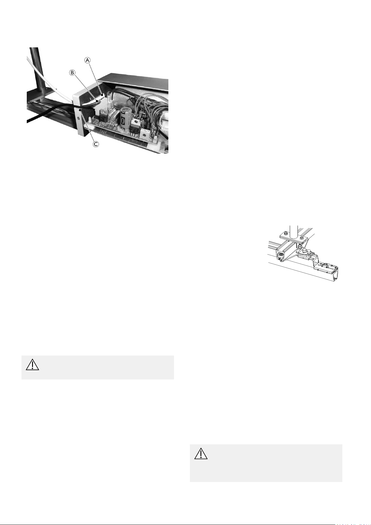
3.10.3Installingandconnectingcontrolbutton andpowersupply
Beforeconnectionofthecontrolbuttonandpowersupply ,
itisnecessarytodismountthecoversonthemotorbox.
Thecoversaredismountedbylooseningthetwoscrews,
whichholdseachcoverandpullingthecovershorizontally
totheside.
Thecontrolswitchismountedintheroomandatthe
height,theuserprefers.Thecontrolswitchisopenedwith
tools,andthebacksideismountedonthewallusingtwo
screwsØ3.5x30mm.
Thewireisshortenedtoasuitablelengthandconnected
tothemotorbox.Seedrawingpos.A.
Thepowersupplyismountedonthewall,visibleor
hidden,dependingonwhatismostsuitable.Thepower
supplyismountedonaØ3.5x30mmscrewonthewall,
usingthe“key”holeonthebacksideofthepowersupply.
Atthebottomofthepowersupplythereisholefora
Ø3.5x30mmscrewwhichmakesitpossibletolockthe
powersupplyonthewall.Thewireisshortenedtoa
suitablelengthandconnectedtothemotorbox.See
drawingpos.B.
Thecoverisre-attached,whenthewiresareconnected
correctlyandthecontrolswitchistested.Rememberto
mountthewiresintheend-plate,inordertoavoidthat
thewireconictswiththecoverwhenitisre-attached.
Seedrawingpos.C.
CAUTION!
Itisveryimportantthattherearenoloose
wireshangingfromthecoupling.
Whentheparallelrailismounted,itisimportanttoensure
acorrectdistancetothecoupling.Seeimageinchapter
Measuresketchfortransitcoupling,page23.
Thetraverserailisadjustedtothespecicorderwhen
itisdelivered.Ifhoweveritisnecessarytoshortenthe
railfurther,itmustbeshortenedintheendoppositeto
wherethecouplingissituated.
Itispossibletousethefollowingtraverserailstogether
withatransitcouplingsystem:
•S,MandL-proles,under-hung
•MandL-prolespartlybetween-hung
Itisveryimportanttoensurethecorrectfreeoverhang
forthetraverserailspacingbetweenthependlesandfree
spanfromtherailstoensurethattherailscancouple
correctly.Seedrawingabove.
Whenthetraversesystemandthecouplingareinstalled
itisveryimportanttocontroltheheightbetweenthese
andadjustifnecessary.
Theloweredgeofthetraverserailmustnotdiffermore
than0.5mmfromthecouplingrail.Ifthereisadifference
inheight,thecouplingtrackmustbethelowest.
Itmaybenecessarytoadjusttheheightdifferently
accordingtotheuserweightortheconditionofthe
ceiling,tooptimizethefunctionofthecoupling.
Whenthelockxturesare
installed,itisveryimportant
thattheyareinlinewith
theendofthetraverserail
andthattheyareturned
correctlycomparedtothe
xtureonthecoupling,
beforetheyarelocked.See
drawing.
LockxturesforM-andL-prolesaredeliveredwitha
littleplate,whichisimportanttoinstall.
3.10.5Installationofasinglerailforacoupling system
Whenthecouplingisinstalledwithasinglerailinoneof
therooms,itispreparedforthis,withoutthelockxture,
whendelivered.
WhenthecouplingisinstalledwithanS-prolerail,the
railiscoupledasshowninchapter3.6.2Railcouplingfor
proleS,page20.
3.10.4Installingatraversesystemwithlock
xturefortransitcoupling
Ingeneralatraversesystemisinstalledasshownin
chapter3.8Mountingtraversesystem,page21.We
recommendthattheparallelrailofthetraversesystemis
mountedintheceilinginordertomakethefunctionof
thetransitcouplingasstableaspossible.
Wheninstallingtheparallelrail,rememberalwaystoplace
aceilingbracket/pendleinfrontofthetransitcoupling,
especiallyontherailclosesttothetransitcoupling.See
chapter3.10.6Mountingthepositioningxturesonparallel
railS-proleandM/L-proles,page24
24
.
Thependleismountedinthecouplingxture.
Therestofthesinglerailsystemisinstalledasshownin
chapters3.2CeilingMountingSystem,page14
Railcoupling,page20.
and3.6
3.10.6Mountingthepositioningxtureson
parallelrailS-proleandM/L-proles
CAUTION!
Itisveryimportantthateverythingisadjusted
correctlyandcarefullyfastenedduetosafety
andfunctionality.
–T estthesystemthoroughlyafterinstallation.
1586749-C
Thepositioningxtureismountedtoeasilypositionthe
A
B
traverserailinproportiontothecoupling.Thextureis
mountedontherailclosesttothecouplingandisturned
towardsthecoupling.Seedrawing.
ThepositioningxturefortheS-prolerailsispartly
mountedinthestandardxture.Itisthereforeimportant
toplaceastandardxturerightinfrontofthecouplingrail.
Installation
Adjustment of positioning xtures
The parallel rail part of the positioning xture c an be
adjusted further by loosening the screws and moving the
xture h orizontally u ntil t he r ail i s r ight i n f ront o f the
coupling.
After adjustment the xture c an b e fastened.
Note that there is some play, which must be divided
between both sides of the rail.
Theonepartofthepositioningxtureismountedinthe
M10boltatthestandardceilingbracketinthesame
directionasthequickxtureonthetraversetrolley .The
traversepartofthepositioningxtureismountedonthe
Quickxtureofthetraversetrolley.Seedrawing.
ThepositioningxtureforM-/L-prolerailsismountedon
respectivelytheparallelandthetraverserail.Thetraverse
partofthepositioningxtureismountedonthequick
xtureofthetraversetrolley.
Thetraverserailandtransitcouplingmustbecoupled
whenmountingtheparallelrailpartofthepositioning
xture.Thiswayitispossibletotickupforcorrect
positionofthexturesbeforetheyaremounted.After
therightpositionistickedup,therailsareseparatedagain
beforetheØ4mmholesforthescrewsaredrilled.See
drawingbelow.
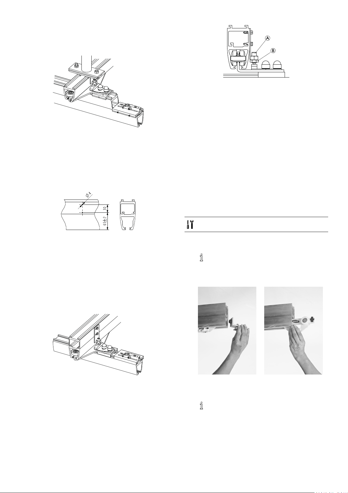
3.11 Installing the ceiling hoist to the rail system
Robin requires a trolley, guiding the ceiling hoist in the rail
system. Robin Mover has the trolley built-in and can be
installed directly to the rail system.
3.11.1 Installing Robin®
Tools:4mmAllenkey;17mmsocketwrench
1.Toinstallthetrolley ,removetheendstopthatis
attachedtotherailsystem.
Insomecountries/localareas,thereisa
demandfordoublesecuringoftheendstops.
Ifanextrasecuringscrewisinstalled,remove
thisscrewbefore.
Adjustmentofhardness
Thepositioningxturesmustbeadjustedtoahardness
thatmakesiteasyforthecouplingtocatchthetraverse
rail,butatthesametime,makesitpossiblefortherailto
passthecouplingwithoutgettingcaughtbythecoupling.
1.Ifthepositioningxtureisadjustedtoohard,loosen
theresilientblackscrewA.
2.Ifthepositioningxtureistoosoft,tightenscrewA.
3.TightenlocknutB(M12)afteranyadjustment.
2.Insertthetrolleyintotherail(nomatterwhichway,
asthetrolleyissymmetric).
3.Re-inserttheendstop.
Insomecountries/localareas,thereisa
demandfordoublesecuringoftheendstops.
Ifanextrasecuringscrewisrequired,install
thisscrew.SeealsoEndStop,page11.
1586749-C25
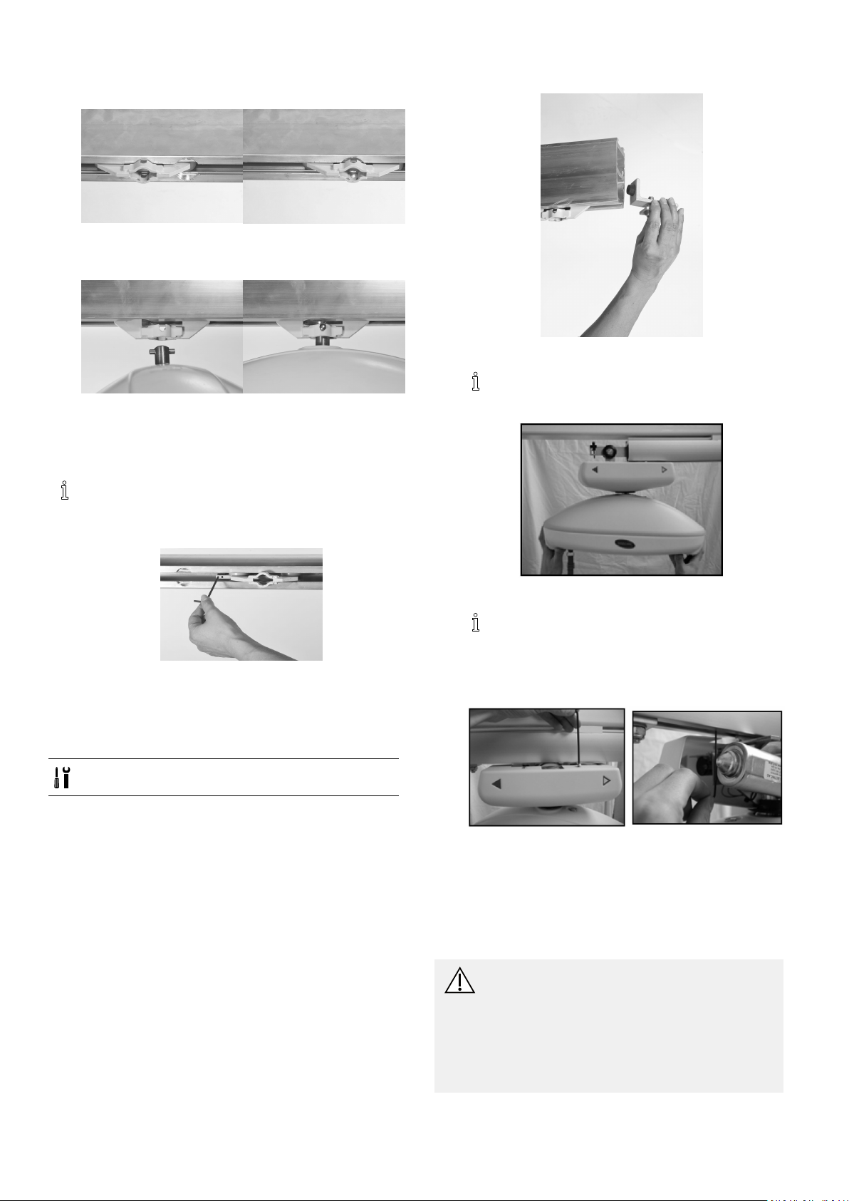
Invacare®EC-Track®
4.LocatethehoisttrolleyattheØ32mmroundrecess
intherail.
5.Liftthehoistandpushthesuspensionpinthrough
thetrolleyopening.
6.Turnthehoistby90degreestoxitinthetrolley.
7.Connectthehandcontrol.
8.Adjustthelengthoftheemergencystop/loweringcord
towithintheuser’sreach.
1.Removetheendstop.
2.Insertthewheelsofthehoistintotherail.
Thedirectionthehoistfacesdoesnotmatter
duringinstallation.
Ifthereisexcessiveresistance,orifthetrolley
unintentionallyrollsbyitselfduetoimbalancein
therailsuspensions,adjustthefrictionbrakeusing
a4mmAllenkey.
3.11.2InstallingRobin®Mover
Thetrolleyisbuilt-inonthehoist,andcanthereforenot
bepreinstalledintherail.
Tools:4mmAllenkey;17mmsocketwrench
3.Installtheendstop.
Tightentheboltto30Nm.
4.Iftoomuchresistanceisexperiencedwhenthe
hoistispulled,orthehoistmovestoofreelyand
unintentionally,adjustthefrictionbrake.
5.Connectthehandcontrol.
6.Adjustthelengthoftheemergencystop/loweringcord
towithintheuser’sreach.
3.12Inspection/checkoftherail
system
CAUTION!
Aftertheinstallationofarailsystem,theentire
systemmustbeinspected.
–Theinspectionofarailsystemmustonlybe
carriedoutbyasuitablyqualiedperson.
–TheinspectionmustfollowtheSafety
inspectionchecklist/Railsysteminthe
Invacare®Robin®ServiceManual.
261586749-C

Installation
InaccordancewiththeEuropeanstandardEN10535,the
systemshallbestresstestedwith300kg.Thisshouldbe
doneateachxingpoint.Thistestiscarriedoutasa
re-testingofthesystemstructuresabilitytosecurethe
railsysteminplace.
1586749-C
27
Invacare®EC-Track®
4TechnicalData
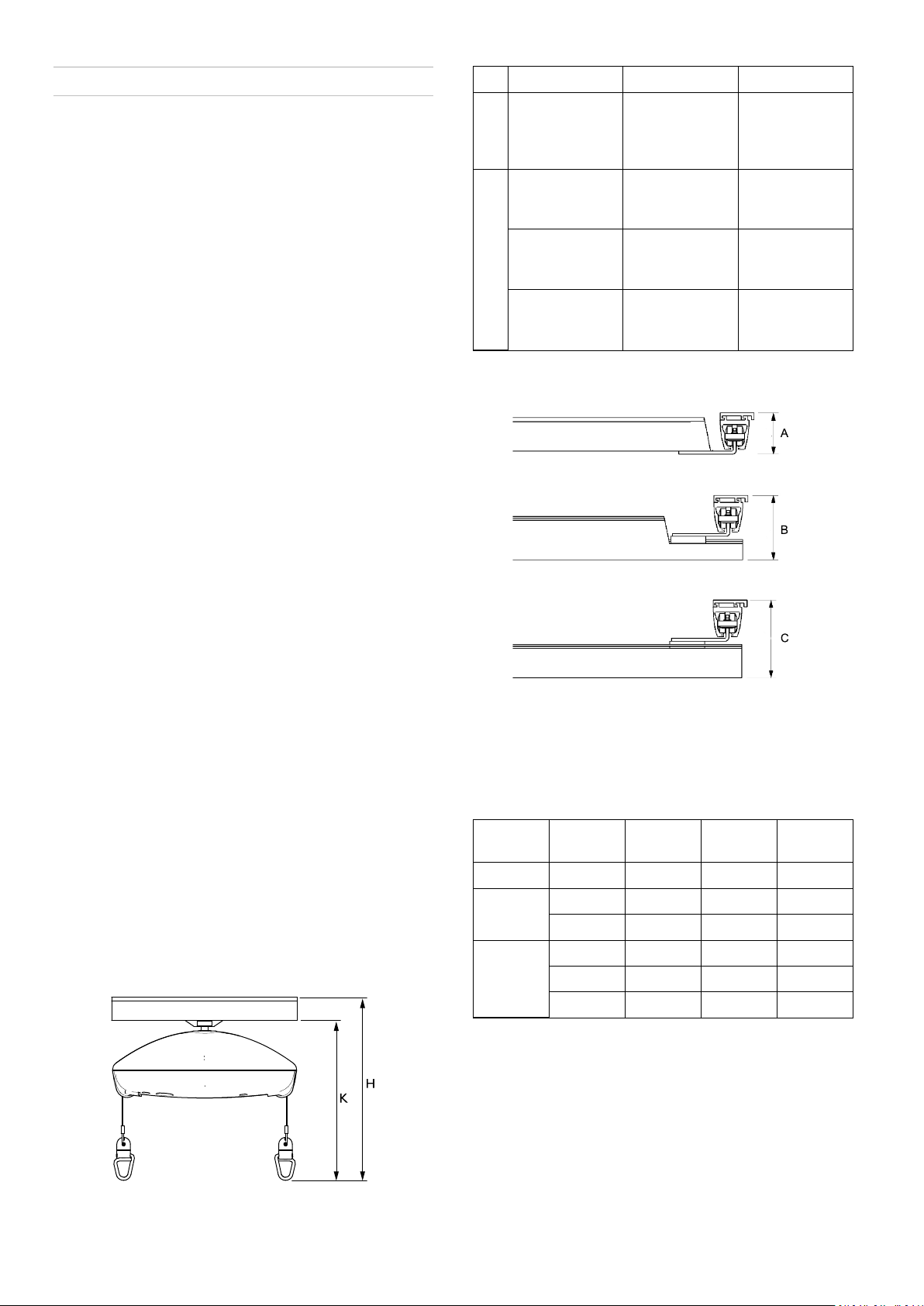
4.1 The rail system
All rail proles a re m anufactured in extruded aluminium.
The rails are available with white powder coating.
The rails are available in three different heights; S= 68
mm, M=114 mm and L=183 mm, providing a fee span of 2
m, 4 m and 8 m, respectively.
The prole width of all three p roles is 58 mm . Th e top of
the proles a re shaped to p ermit the coupling of the rails
to the installation brackets.
On delivery, the rail for the hoist will feature a milled
groove on its bottom. This groove is used for hoist
installation and is called keyhole.
Possible installations
Single rail can be installed on the ceiling or onto the wall
and oor. T he r ail p osition i n t he r oom c an b e either
parallel to a wall or angular in relation to a wall.
The traverse system can be installed on the ceiling or onto
the wall and oor. T he free s pan between t he two parallel
rails can be up to 8000 mm.
K
Measuredfrom
beneaththe
railtothesling
hook
H
Ceiling
mounted
RailproleS
Wall/oor
mounted
RailproleM
Wall/oor
mounted
RailproleL
Traverserailsystemheight
Robin Robin Mover
336mm396mm
410mm470mm
450mm510mm
519mm579mm
Curves are available in the S-prole a nd c an b e installed
on the ceiling. They are available in angles of 30°, 45°,
60° and 90°.
Special solutions
Installation with pendling brackets is used in the following
cases: When the height of the ceiling varies in the
lengthwise direction of the rail, or when the rail is to be
countersunk.
Angular installation is used when the rail has to be
installed in other angles than 90°.
4.2 Dimensions for different track installations
The building dimensions of an installation is dened as
the distance between the ceiling underside and the hooks
of the hoist.
Single rail height
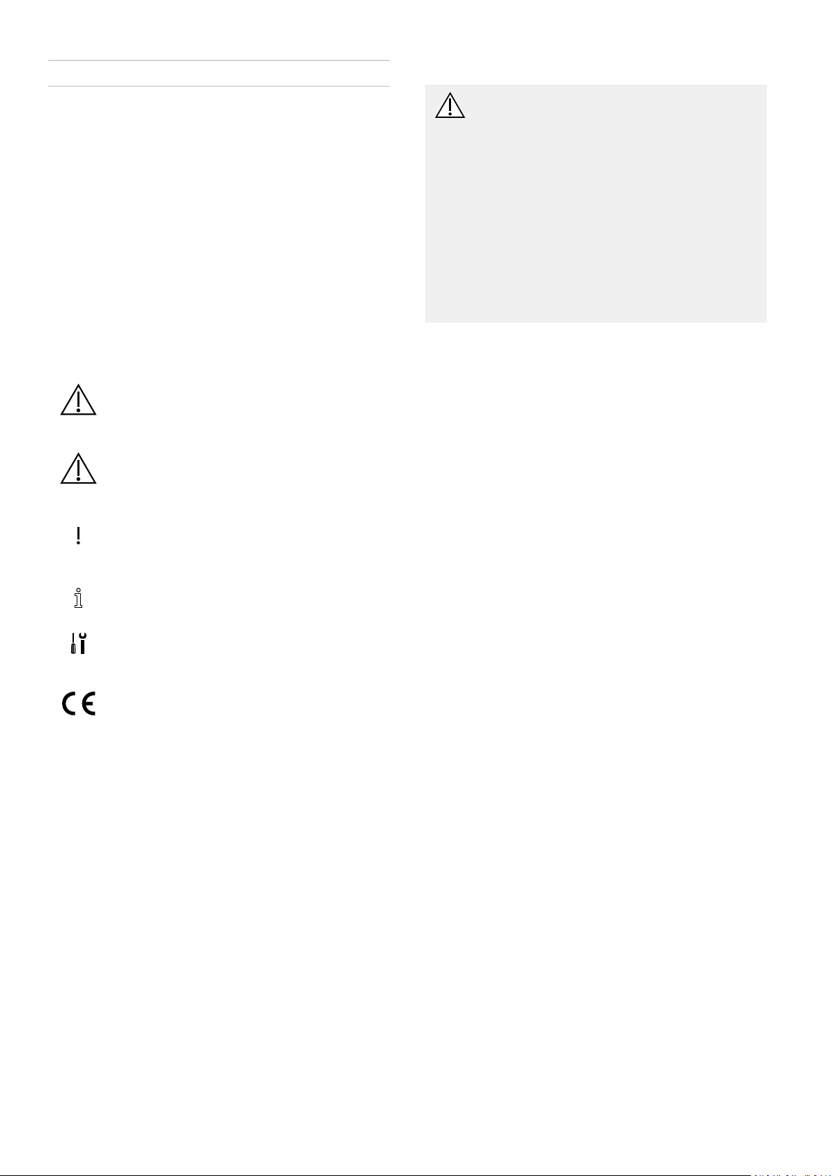
For the EC-Track system and Robin ceiling hoist, the
dimensions for being built-in, measured from the ceiling
with the rail mounted as close as possible to the ceiling,
are:
A=Between-hungtraverse
B=Partlybetween-hungtraverse
C=Under-hungtraverse
Possiblecombinations
Traverse
rail
S-proleS-prole
M-prole
L-prole
Parallel
rail
83mm
S-prole
M-prole
S-prole
M-prole
L-prole
129mm203mm250mm
198mm272mm388mm
A
—
——
——
B
—
156mm203mm
C
156mm
272mm
319mm
281586749-C

Indholdsfortegnelse
FORHANDLER:Opbevardennemanual.Procedurerneidenne
manualSKALudføresafenuddannettekniker.
1Generelt........................................30
1.1Omdennemanual.............................30
1.2Generelsikkerhed..............................30
1.3Garantioplysninger.............................30
2Skinnesystem.....................................31
2.1Enkeltskinnesystem.............................31
2.2Køresystem...................................32
2.3Forytningtilellerfralokale......................33
2.4Skinner,beslagogtilbehør........................34
3Installation.......................................39
3.1Generellemonteringsanvisninger...................39
3.2Loftsmonteringssystem..........................39
3.2.1Betonloft..................................39
3.2.2Betonloftmedophængtloft....................40
3.2.3Træloft...................................42
3.3Vægmontering–endeophængtskinne...............43
3.3.1SkinneprolMogL..........................43
3.4Vægmontering–sideophængtellerside-/endeophængt
beslag......................................44
3.5Kurver.......................................44
3.6Skinnetilkobling................................45
3.6.1SkinnetilkoblingtilprolMogL.................45
3.6.2SkinnetilkoblingforprolS.....................45
3.7Vægstøtteben.................................46
3.8Monteringafkøresystem.........................46
3.9Installationafskinneskift.........................47
3.10Transitkobling................................47
3.10.1Justeringafhulletivæggen/døråbningen.........47
3.10.2Monteringaftransitkoblingen..................48
3.10.3Monteringogtilslutningafbetjeningsknapog
3.10.4Monteringafetkøresystemmedlåseanordningtil
3.10.5Installationafenenkeltskinnetilet
3.10.6MonteringafplaceringsholdernepåS-prolenog
3.11Monteringafløftemotorenpåskinnesystemet........50
3.11.1MonteringafRobin®........................50
3.11.2MonteringafRobin®Mover...................51
3.12Eftersyn/kontrolafskinnesystemet.................51
4T ekniskeData.....................................53
4.1Skinnesystemet................................53
4.2Måltilforskelligeskinneinstallationer................53
strømforsyning.............................49
transitkobling..............................49
koblingssystem.............................49
M/L-prolenforparallelskinne.................49
Invacare®EC-Track®
1Generelt
1.1Omdennemanual
Denneinstallationsmanualerberegnetsomenvejledning
tilatplanlæggeogudføreinstallationen.Foratvikan
garanteresikkerhedenvedhåndteringafproduktet,skal
manualenlæsesomhyggeligt,ogsikkerhedsanvisningerne
skalfølges.
Seoplysningeromforsalgogbrugeroplysningeri
brugsanvisningen.Dukanndebrugsanvisningen
påInvacareshjemmesideellervedatkontaktedin
Invacare-forhandler(seadressersidstidennemanual).
Symboleridennemanual
Idennemanualvisesfaresituationermedsymboler.
Symbolerneledsagesafetsignalord,derangiver ,hvor
alvorligrisikoener.
ADVARSEL
Angiverenpotentieltfarligsituation,somkan
resultereialvorligkvæstelseellerdødsfald,
hvisdenikkeundgås.
FORSIGTIG
Angiverenpotentieltfarligsituation,somkan
resultereienmindreellerlillekvæstelse,hvis
denikkeundgås.
VIGTIGT
Angiverenpotentieltfarligsituation,somkan
resultereibeskadigelseafejendom,hvisden
ikkeundgås.
Tipsoganbefalinger
Givernyttigetips,anbefalingerogoplysninger,
dersikrereneffektiv,problemfrianvendelse.
Indeholderoplysningeromdetnødvendige
værktøj.
DetteprodukterCE-mærketi
overensstemmelsemedforordningen
2017/745ommedicinskudstyriklasse1.
Lanceringsdatoenfordetteproduktfremgår
afCE-overensstemmelseserklæringen.
1.2Generelsikkerhed
ADVARSEL!
Sikkerhedsreglerførmontering
–Alleinstallationerskaloverholdedenationale
reglerogstandarder.
–Brugkungodkendteinstallationskomponenter.
–Påhvertenkeltophængspunktskal
tag-/loftsstrukturenkunnebæreenstatisk
vægtpåmindst300kg.
–Førmonteringafetkøresystemskaltag,
væggeoggulvundersøgesgrundigt.Udfør
enpræcisvurderingaf,hvilkematerialer
derndesitagetogvæggene.Denne
undersøgelsemåkunforetagesafen
kompetentperson.
–Skinnesystemetmåkunmonteresaf
kompetentepersoner .
Stresstest
IhenholdtildeneuropæiskestandardEN10535skal
systemetstresstestesmed300kg.Detteskalgørespå
hvertenestefastgørelsespunkt.Dennetestskaludføres
somentestafsubstratetsevnetilatholdeskinnesystemet
påplads.Dennetestskalforetagesafenkompetent
person.
1.3Garantioplysninger
Garantivilkårog-betingelserindgårivoresgenerellevilkår
ogbetingelser ,dergælderspeciktforderespektivelande,
hvorproduktetsælges.
KontaktoplysningernetildinlokaleInvacare-forhandler
ndesindvendigtpåbagsidenafdennebrugsanvisning.
301586749-C
 Loading...