

Invacare Delta II Service Manual
Service-Anleitung Invacare
®
Delta II
1
SERVICE MANUAL
Invacare® Delta II
This manual includes instructions on
troubleshooting &
repair
Version: 01.02

Invacare® Delta II Service-Anleitung
2

Service-Anleitung Invacare
®
Delta II
3
Table of Contents
Section Page
1 General Considerations.................................................................................... 5
Before You Start.................................................................................................................................. 5
1.1 Service Technician Qualification............................................................................................ 5
1.2 The Invacare
®
Service............................................................................................................ 5
1.3 Transport to the Manufacturer ............................................................................................... 5
2 Safety and Assembly Guidelines ..................................................................... 6
2.1 Symbols used in this Service Manual .................................................................................... 6
2.2 Before any Inspection andRepair:.......................................................................................... 6
2.3 During Assembly / Disassembly ............................................................................................ 7
2.4 Prior to Operation / After Completion of Service:................................................................... 7
2.5 Tool List.................................................................................................................................. 7
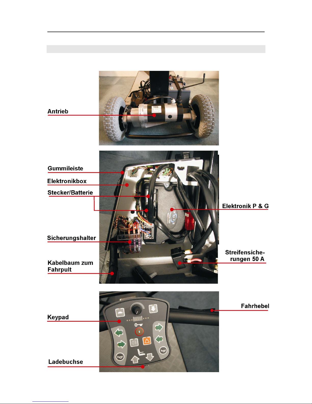
3 The Invacare® Delta II........................................................................................ 9
3.1 Arrangement of Modules, Components and Operator Controls ............................................ 9
3.2 Electronic Control Components, Electrics............................................................................ 11
3.3 Module Composition / Variants, Accessories....................................................................... 12
3.3.1 Module Composition, Variants......................................................................................... 12
3.3.2 Accessories...................................................................................................................... 12
4 Inspection Procedures.................................................................................... 14
5 Troubleshooting .............................................................................................. 17
5.1 General Considerations .......................................................................................................17
5.2 Root Causes ........................................................................................................................ 17
6 Fault Diagnostics with the Status Indicator or the Penny & Giles SP1
Programming Unit ........................................................................................... 19
6.1 Status Indicator Error Codes................................................................................................ 19
6.2 P & G Programming Unit Error Codes ................................................................................. 19
6.3 Fault Types and their possible Root Causes ....................................................................... 21
7 Repair and Replacement................................................................................. 23
7.1 Replacing Shrouds............................................................................................................... 23
7.1.1 Side Shroud ..................................................................................................................... 23

Invacare® Delta II Service-Anleitung
4
7.1.2 Rear Shroud, Cable Harness/Lights................................................................................ 24
7.2 Wheels ................................................................................................................................. 26
7.2.1 Driving Wheels................................................................................................................. 26
7.2.2 Front Wheel ..................................................................................................................... 27
7.2.3 Cover, Tube ..................................................................................................................... 28
7.3 Front Wheel Axle-tree .......................................................................................................... 29
7.4 Batteries ............................................................................................................................... 30
7.4.1 Checking Batteries, Battery Cables and Strip Fuse ........................................................ 30
7.4.2 Disassembling the Batteries ............................................................................................ 31
7.4.3 Assembling the Batteries ................................................................................................. 31
7.5 Electronic Box and Components.......................................................................................... 32
7.5.1 Disassembling the Electronic Box ................................................................................... 32
7.5.2 Disassembling the Components...................................................................................... 32
7.6 Seat Unit............................................................................................................................... 33
7.6.1 Seat.................................................................................................................................. 33
7.6.2 Slide Rails ........................................................................................................................ 34
7.6.3 Armrests........................................................................................................................... 34
7.6.4 Seat Plate ........................................................................................................................ 35
7.6.5 Seat Post ......................................................................................................................... 36
7.7 Drive ..................................................................................................................................... 37
7.7.1 Disassembling the Drive Unit........................................................................................... 37
7.7.2 Disassembling the Components...................................................................................... 37
7.8 Tiller, Console, Keypad ........................................................................................................ 38
7.9 Tiller Shaft Shroud, Tiller Shaft ............................................................................................39
7.10 Front Shroud, Front Wheel Fork, Lights, Horn..................................................................... 42
7.11 Chassis................................................................................................................................. 43
8 Appendix:......................................................................................................... 45
8.1 Circuit Diagram .................................................................................................................... 45

Service-Anleitung Invacare
®
Delta II
5
1 General Considerations
Before You Start
This service manual contains information and instructions required to service and repair the Invacare
®
Delta II.
You must comply with the instructions in this service manual when attempting any scooter service or
repair. The general service and care instructions included in the operating manual apply.
Please observe the safety guidelines.
Please consult the spare part catalogue for information on ordering spare parts.
1.1 Service Technician Qualification
The Delta II may be serviced and repaired by qualified personnel only. Minimum requirements:
Relevant training for instance as two-wheel or orthopaedic mechanic or extensive relevant
experience.
Competent handling of electrical measuring instruments (multimeter).
1.2 The Invacare®Service
If you have any problems or queries, please contact Invacare® Service:
Head Office: Tel.: 05731-754-0
Fax: 05731-754-111
Service Department: Tel.: 05731-7545-(70-80)
Fax: 05731-7542-(08-16)
Street Address: Invacare
®
Deutschland GmbH TILLVERKARE
Dehmer Str. 66
32549 Bad Oeynhausen
Post Box: Invacare
®
Deutschland GmbH
Postfach 60 01 06
32527 Bad Oeynhausen
• Any modifications of the Invacare
®
Delta II arising from improper or faulty service or repairs will
lead to exclusion of liability from Invacare
®
.
1.3 Transport to the Manufacturer
If the Invacare® Delta II must be shipped to the manufacturer for major repairs, use the original
packaging for shipping if at all possible.
Include a description of the fault which should be as accurate as possible.

Invacare® Delta II Service-Anleitung
6
2 Safety and Assembly Guidelines
The safety guidelines are essential for compliance with health and safety regulations and must be
observed at all times.
2.1 Symbols used in this Service Manual
9
NOTE:
This symbol indicates proper servicing procedures as well as particularities and simpler ways
of disassembly/assembly.
WARNING:
The warning symbol indicates possible hazards either to the service
technician or the Invacare® Delta II. It is imperative that you observe any
safety instructions marked with this symbol. The word “Danger!”
indicates that failure to heed the warning may result in significant
personal injury or death.
2.2 Before any Inspection andRepair:
WARNING:
DANGER!
Consider the sometimes significant weight of the components. This is
particular important when disassembling the drive units and batteries.
Ensure that you can safely handle and store the components.
WARNING:
DANGER!
Personal injury may occur! Before you attempt any work on the
batteries, remove your wristwatch and any metal rings, bracelets and
chains. You may short the batteries or cables and components directly
connected to the batteries. A short may cause severe injuries.
Before you attempt any work carefully study this Service Manual and the associated Operating Manual
and comply with the instructions therein. Ensure that you meet the minimum qualification
requirements (refer to “General Considerations” section).
Prior to disassembling any live components, ensure that the Invacare
®
Delta II has no power. To do
this, first remove the negative and then the positive terminal connector from the batteries and lift out
the batteries.
Use perfect, undamaged tools only.
Service-Anleitung Invacare
®
Delta II
7
Avoid shorting out contacts when taking readings on live components.
2.3 During Assembly / Disassembly
Prior to disassembly note and mark the current wheelchair settings (seat, armrest, back, etc.) and the
associated cable connectors. This will simplify later re-assembly. This manual describes the
disassembly procedure.. If no information is given in relation to assembly or mounting, re-assemble
the components in reverse order of disassembly. You will find any differing assembly procedures or
special assembly guidelines after the description of the disassembly procedure.
WARNING:
Before attempting any disassembly or re-assembly secure the lifted
wheelchair with suitable supports.
Do not use “normal” nuts in place of self locking nuts.
Always use the correct size for washers or spacers.
9 NOTE:
Connectors
All connectors are secured with mechanical locking mechanisms preventing the connector
from working loose during operation.
To remove the connectors push in the locking mechanism. Squeeze the locking mechanism
together on the top and bottom of the connector.
When re-assembling the components, ensure that the connector locking mechanisms are
properly engaged.
Batteries:
If you need to place the Delta II on its side during service remove the batteries before doing
so.
Orientation:
Any instructions involving directions such as “left” and “right” always refer to the direction of
motion assuming the user is standing behind the Delta II.
2.4 Prior to Operation / After Completion of Service:
WARNING:
Ensure that all attaching hardware is tightened securely. Verify that all
parts are locked correctly. Operate wheelchair with required tyre
pressure (2.0 bar or 29 psi) only.
Upon completion of the service, verify proper functioning of the
replaced components and test drive the vehicle.
2.5 Tool List
You will need a standard tool kit containing at least the following tools:

Invacare® Delta II Service-Anleitung
8
Set of open-jawed and ring spanners
Set of Allen keys
Torque wrench (standard)
Socket spanner set
Set of screw drivers (flat tip, cross tip, torx)
Side cutter
Flat nose pliers
Round nose pliers
Pointed pliers
Crimping tool
Mallet or plastic mallet
Tyre repair kit (standard)
Tire gauge
Tire pump
Valve removal tool
Puller and pressing or hitting tool for ball bearings
Multimeter with probe tips and various cable clamps
30 W soldering iron
Riveting tool
Service-Anleitung Invacare
®
Delta II
9
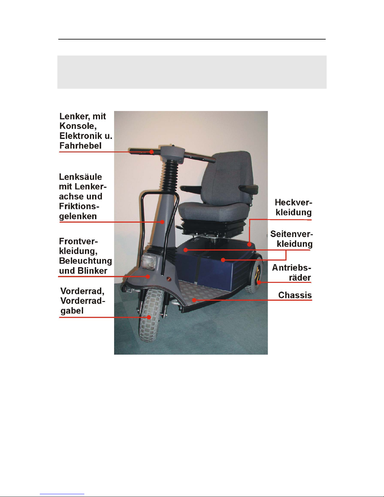
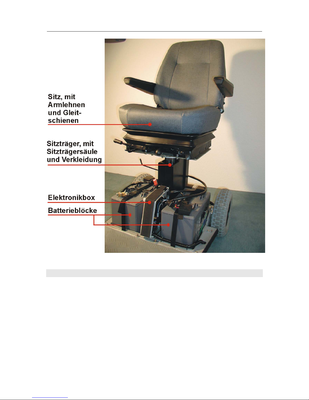
3 The Invacare® Delta II
3.1 Arrangement of Modules, Components and Operator Controls
Invacare® Delta II Service-Anleitung
10
Service-Anleitung Invacare
®
Delta II
11
3.2 Electronic Control Components, Electrics

Invacare® Delta II Service-Anleitung
12
3.3 Module Composition / Variants, Accessories
3.3.1 Module Composition, Variants
The Invacare
®
Delta II can be supplied with the following options:
• Batteries (Section 6.4)
x 12V/50 AH (Sonnenschein)
x 12V/70 AH (MK Batteries)
x 12V/70 AH (Sonnenschein)
• Throttle Control Lever (Section 6.8)
x Foot throttle
• Driving Wheels (Section 7.2.1)
x “Wide” driving wheel 4.10 / 3,50 x 6“
x “Narrow” rear wheel 3.00 x 8“
• Anti-tip Wheels (refer to Operating Manual)
• Front Wheel (Section 7.2.2)
x Front wheel 4.10 / 3,50 x 6“
• Lights (Sections 7.1.2 and 7.10)
• Electric Seat Height Adjustment (see Accessories)
• Back Elements
x Adjustable back element
• Headrest (see Accessories)
• Legrests (see Accessories)
x Manually adjustable legrests with ergonomic length compensation
• Cane Holder (see Accessories)
3.3.2 Accessories
The following accessories are available for the Invacare
®
Delta II:
• Chargers
x Charger 8 A
x Charger 10 A (MEDICO)
x Charger 12 A
• Basket cpl.
x Basket
x Basket holder
• Cane holder cpl.
x Cane holder bottom
x Cane holder top
x Plug 30 x 15
x Cane holder clamp
x Elastic cord, D = 4 mm, L = 60 mm
x Cane holder support, fender
• Crutch Holder
x Seat mountable
x Fender mountable
• Hip Strap
• Headrest KAB, grey
• Legrest
x RH, LH
• Mirror

Service-Anleitung Invacare
®
Delta II
13
x Basket-mountable
• Hour Meter
• Spring Module, Standard, cpl.
x Spring module
x Intermediate plate
x Seat plate
• Spring Module with Shock Absorber and Slide Rails
x Spring module
• Self-adhesive Bags
• Programming Unit
x Standard, for customers
x P & G, for technicians
• Baby Seat
• Wide Angle Mirror
• Hand Brake
• Trailer
x Trailer coupling
• Dust Cover
• Additional Horn
Invacare® Delta II Service-Anleitung
14
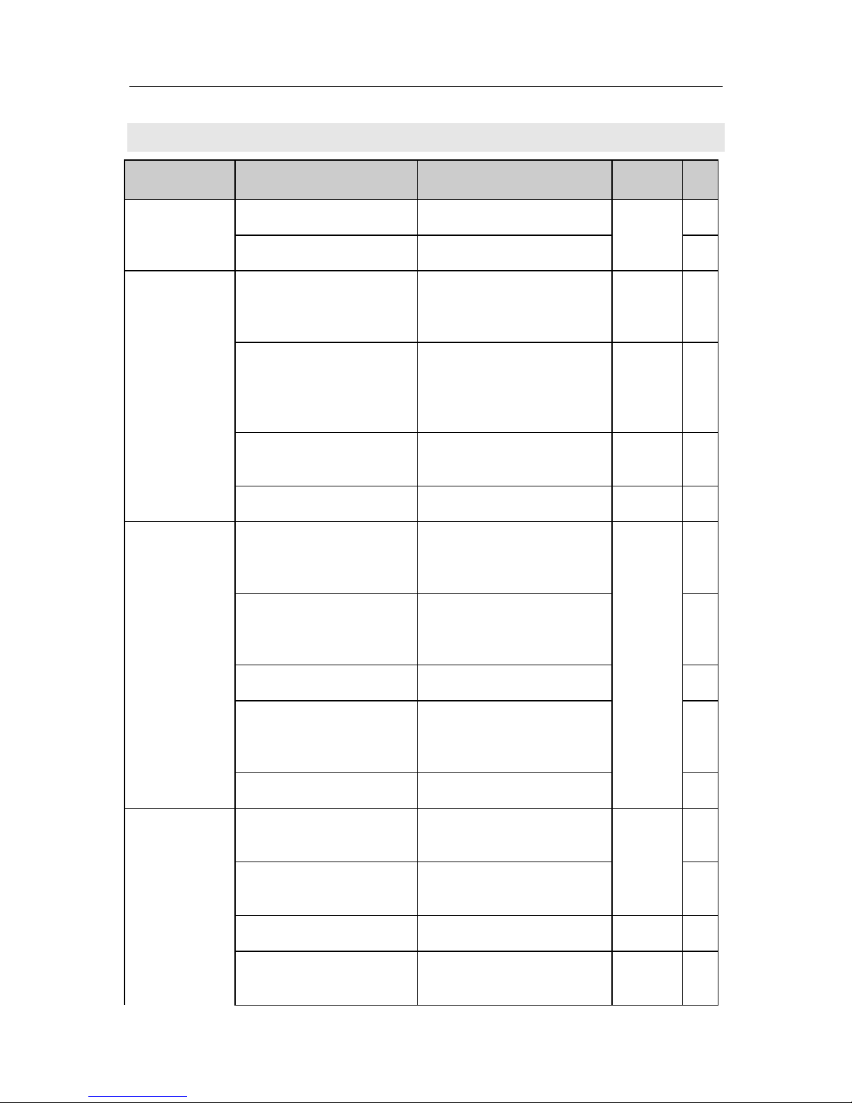
4 Inspection Procedures
Component Inspection Action Section
9
• Check for damage ⇒ Replace parts
Shrouds: Rear,
Side, Seat Post
Shroud
• Check shroud attachment ⇒ Tighten or replace screws
7.1, 7.6.5
Wheels:
Driving Wheels,
Front Wheel
• Check rear wheels for
side movement and
proper tension
⇒ Check mounting plate
screws and locks
7.11
• Check front wheel for
proper tension, side
movement and that it is
spinning freely.
⇒ Adjust or replace wheel,
axle, wheel bearing or fork
7.2.2
• Check front wheel fork
bearing
⇒ Replace bearing
7.10
• Check tyres ⇒ Re-mount
7.2.3
Batteries
• Check for damaged
batteries & corroded
contacts
⇒ Clean contacts, replace
batteries
7.4, 7.5
• Check contacts,
terminals, cables and
strip fuses
⇒ Tighten, replace if
necessary
• Check battery voltage ⇒ Charge or replace batteries
• Check 50 A strip fuses
and 15 A fuses
(electronic box)
⇒ Replace fuses
• Check battery straps ⇒ Tighten or replace straps
Electronics
• Console/keypad
status indicator flashing
⇒ Identify flash code
6.1
• Check cable, cable ties,
connectors
⇒ Tighten, replace
• Functions ⇒ Diagnostics
6.1, 6.2
• Voltage supply ⇒ Replace cable, connector
or electronics
7.4
 Loading...