

Invacare Dahlia 30, Dahlia 45 Service Manual
Dahlia®30/45
enManualwheelchairpassive
ServiceManual
DEALER:Keepthismanual.
TheproceduresinthismanualMUSTbeperformedbyaqualified
technician.
Dahlia 4 5

©2014Invacare®Corporation
Allrightsreserved.Republication,duplicationormodificationinwholeorinpartisprohibitedwithoutpriorwritten
permissionfromInvacare.Trademarksareidentifiedby™and®.AlltrademarksareownedbyorlicensedtoInvacare
Corporationoritssubsidiariesunlessotherwisenoted.

Contents
1General.......................................4
1.1Introduction..................................4
1.2Deliverycheck.................................4
1.3Customerservice..............................4
2Assembly......................................5
2.1Changingthebackresttubes.......................5
2.2Placingthewires...............................6
2.2.1Wireswithbackrestplate......................6
2.2.2Wireswithtensionadjustablebackrest............6
2.3Tiltscalebackrest..............................7
2.4Tiltscaleseat..................................7
2.5Mountingtheattachmentfortabletray...............7
2.6Mountingthetabletray..........................7
2.7Mountingtherearwheels.........................7
2.8Mountingtheusermaneuveredtilt..................8
2.9Mountingthefootoperatedtilt.....................9
2.10Reducingtiltand/orbackrestrecline...............9
2.10.1Mountingofthetilt/reclinereductionbushing.......9
2.10.2Mountingthetiltreductionblock................9
2.11Repositioningthebackrestjoint...................10
2.12Mountingthelegrestattachmentforhighposition......10
2.13Mountingtheaccessorytray......................10
2.14Mountingthedrumbrake........................11
2.14.1Drumbrakefor16”wheels....................11
2.14.2Drumbrakefor22–24”.......................11
2.15Mountingtheone—armdrive.....................12
2.16Changingthehandrimforone—armdrive...........13
2.17Mountingthefootoperatedbrake..................13
3SettingsandAdjustments........................15
3.1Backrestplate.................................15
3.1.1Heightadjustmentbackrestplate.................15
3.1.2Widthadjustmentbackrestplate.................15
3.2SpecialadaptationofFlex3backrest.................16
3.3Tensionadjustablebackrest.......................16
3.3.1Adjustmentheight—tensionadjustablebackrest.....16
3.3.2Widthadjustment—Tensionadjustablebackrest.....16
3.3.3Angleadjustment—Tensionadjustablebackrest.....17
3.4Positioningtheheadrest/neckresttothefront..........17
3.5Adjustingtheuser/footoperatedtilt.................18
3.6Armrest.....................................18
3.6.1Adjustingthearmrestheight....................18
3.6.2Adjustingthearmrest/siderestdepth..............18
3.7Adjustingtheseatdepth..........................19
3.8Adjustingtheseatwidth..........................19
3.9Rearwheels..................................19
3.10Adjustingtheseatheightandbalancepointwiththe
rearwheelattachment..........................19
3.10.1Rearwheelattachment—standardposition........19
3.10.2Turningtherearwheelattachment...............20
3.10.3Rearwheelattachmentmountedontheopposite
side.....................................20
3.10.4Rearwheelattachmentturned—oppositesides.....20
3.10.5Rearwheelattachment—depthadjustment........20
3.11Castorattachment.............................21
3.11.1Castorattachment—adjustments...............21
3.12Mountingtheseatplateextension..................22
3.12.1Seatplateextensiontothefront................22
3.12.2Seatplateextensiontotherear.................22
3.12.3Seatplateextensionsidewise...................22
3.13Widthadjustment.............................22
3.14Adjustingthewidthofthelegrest..................23
3.15Centrallegrest................................23
3.15.1Adjustingtheheightofthecentrallegrest..........23
3.15.2Adjustingthefootangleofthecentrallegrest.......23
3.15.3Adjustingthedepthofthecentrallegrest..........23
3.15.4Adjustingtheangleofthecentrallegrest..........23
3.16Adjustingthecalfpads..........................24
3.17Assemblethepelvicbeltforpositioning..............24
3.17.1Assemblepelvicbelttofrontattachment..........24
3.17.2Assemblepelvicbelttorearattachment...........24
3.18Adjustingthewidthoftheaccessorytray.............24
3.19Adjustingthedepthoftheaccessorytray............25
3.20Adjustingthebrakeeffect........................25
3.20.1Userbrake—adjustment.....................25
3.20.2Drumbrake—adjustments...................25
3.20.3Footmaneuveredbrake—adjustments...........26
4Maintenance...................................27
4.1Safetyinformation..............................27
4.2Flattire......................................27
4.3Cleaning.....................................27
4.4Washinganddisinfection.........................27
4.5Reconditioning.................................27
4.5.1Checklistforreconditioning....................29
5AfterUse......................................30
5.1Recycling.....................................30
5.2Wastedisposal................................30
6Troubleshooting................................31
6.1Limitationareas—Troubleshooting.................31
6.1.1Seattilt...................................31
6.1.2Seatdepth.................................31
6.1.3Backrestrecline.............................31
7Technicaldata..................................32
7.1Dimensionsandweights..........................32
7.2Environmentalconditions.........................33
7.3Seatheighttables...............................33

Dahlia®30/45
1General
1.1Introduction
Thisservicemanualcontainsinformationabouttechnicaladjustments,
technicaldata,descriptionsofhowaccessoriesarepersonallyfitted
andslightlymoreadvancedsettings.
Thismustbereadthoroughlybytheresponsibletechnicianor
assistingpersonwhenadaptingthewheelchair.
WARNING!
Riskofinjury
Ifthesetupofthewheelchairisimproper,itmaynot
functionproperly.
–Changestothewheelchairshouldonlybecarriedout
bytrainedpersonnel.
Forpre-saleanduserinformation,pleaseseetheuser
manual.TheusermanualcanbefoundonInvacare’swebsite.
1.2Deliverycheck
Anytransportdamagemustbereportedimmediatelytothetransport
company.Remembertokeepthepackaginguntilthetransport
companyhascheckedthegoodsandasettlementhasbeenreached.
1.3Customerservice
Forcontactdetailspleaserefertothelastpageofthispublication
whereyouwillfindtheaddresstoyourlocalEuropeansalescompany.
4
1572308-B

Assembly
2Assembly
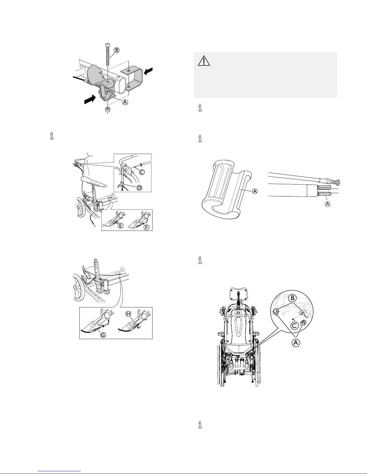
2.1Changingthebackresttubes
1.
B
ReleasetheknobAandremovethepushhandles/pushbarB.
2.
C
C
ReleasethesafetyshackleCandcarefullyremovethesafety
pinfromtheattachment.
3.
LoosenandremovethescrewwasherandnutDfromthe
backrestattachment.
Whenre-mountingthebackrest(seeinstructions
below),anewscrewmustbeused,theoldonemust
bescrapped.
4.
4x
x4
D
E
F
LoosenthefourscrewsforthebackresttubesDandturnthe
attachmentsEinordertoreleasethebackresttubeF.
Donotremovethescrews.
5.
H
2x
G
MounttheattachmentsfortheMatrXbackrestGandtighten
thescrewsH.
Tools:5mmAllenkey
6.
2x
J
MountthebackresttubesIontheattachmentknobsJon
thebackrest.
Startwiththelowerattachment.
7.
Re-mountthebackrestonthewheelchair,replacethescrewand
tightenthescrew,washerandnutK(9Nm).
1572308-B5
Dahlia®30/45
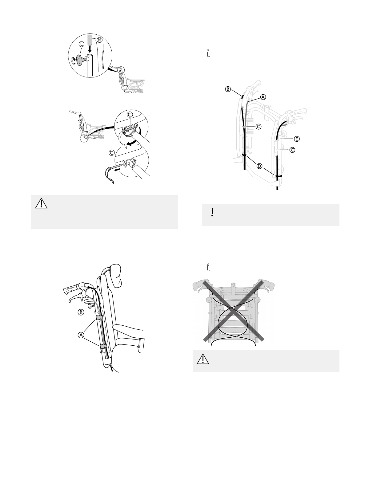
8.
L
M
MountthepushbarMandtightentheknobL.
9.
C
C
Re-mountthesafetyshackleCandattachthegaspiston.
WARNING!
Safetyrisk
Thewheelchairmaycollapse
–Remembertoalwaysreinsertandfastenthesafetypin
whenithasbeenremoved.
2.2Placingthewires
2.2.1Wireswithbackrestplate
A
B
1.ThreadthewiresontheoutsideofthebackresttubesB.
2.Placethewiresintheholders/clipsAinordertoholdthemin
place.
Foldtheslackofthewiresundertheseattogetthem
outoftheway.
2.2.2Wireswithtensionadjustablebackrest
A
B
C
C
D
E
1.PlacethewiresAandBasshownonthepictureabove.
Riskofdamagetothewires
–Itisimportantthatthecablefortheassistantbrake
Aisplacedontheinsideofthebackresttubes.
2.Placethewireforthebackrest/seatreclineBoutsideofthe
backresttubes.
3.Placebothofthewiresontheinsideofthebackrestattachment
C.
4.AttachthewirestothebackresttubesEwiththestrapsD.
Foldtheslackofthewiresundertheseattogetthem
outoftheway.
CAUTION!
Riskofreducedbrakeeffect
–Thewiresmustnotbecrossedonthebackrest!
61572308-B
Assembly
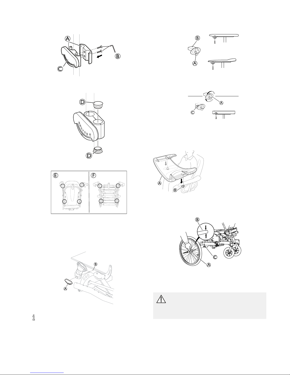
2.3Tiltscalebackrest
1.
A
B
C
AttachtheclampsAwiththetiltscaleCtothepushbar/push
handlesorthebackresttubesandtightenthescrewsB.
2.
D
D
PlacetheendplugsDintheemptyholes.
3.
E F
Placethetiltscaleforthebackrestangleonthepushbar/push
handleoronthebackresttubesaccordingtopictureEorF
above.
2.4Tiltscaleseat
1.
A
B
PlacethetiltscalefortheseatAontheseatframeB.
Thetiltscaleshouldbeplacedontheleftside.
2.5Mountingtheattachmentfortabletray
1.
A
B
MountthetableattachmentAwiththeattachmentpartfacing
outwards.TheplainsurfaceBoftheattachmentshouldbe
placedupwardswhenusingthetableonthethinarmrests.
2.
A
C
TofitthetableattachmentAtothewidearmrest,turnthe
attachmentaround,thepatternedsurfaceCshouldnowbe
facingupwards.
2.6Mountingthetabletray
A
B
MountthetabletrayAinthetabletrayattachmentsB.
2.7Mountingtherearwheels
B
A
C
1.Pressandholdinthequick-releasebuttonA.
2.PlacetherearwheelaxleBintherearwheelattachmentC.
3.Pullthewheelsoutwardstocheckthatthewheelissecurely
lockedinposition.
WARNING!
Riskofinjury
–Checkthattherearwheelissecurelylockedin
position!Itshouldnotbepossibletoremovethe
wheelswhenthequick-releasebuttonAisinactivated.
1572308-B7
Dahlia®30/45
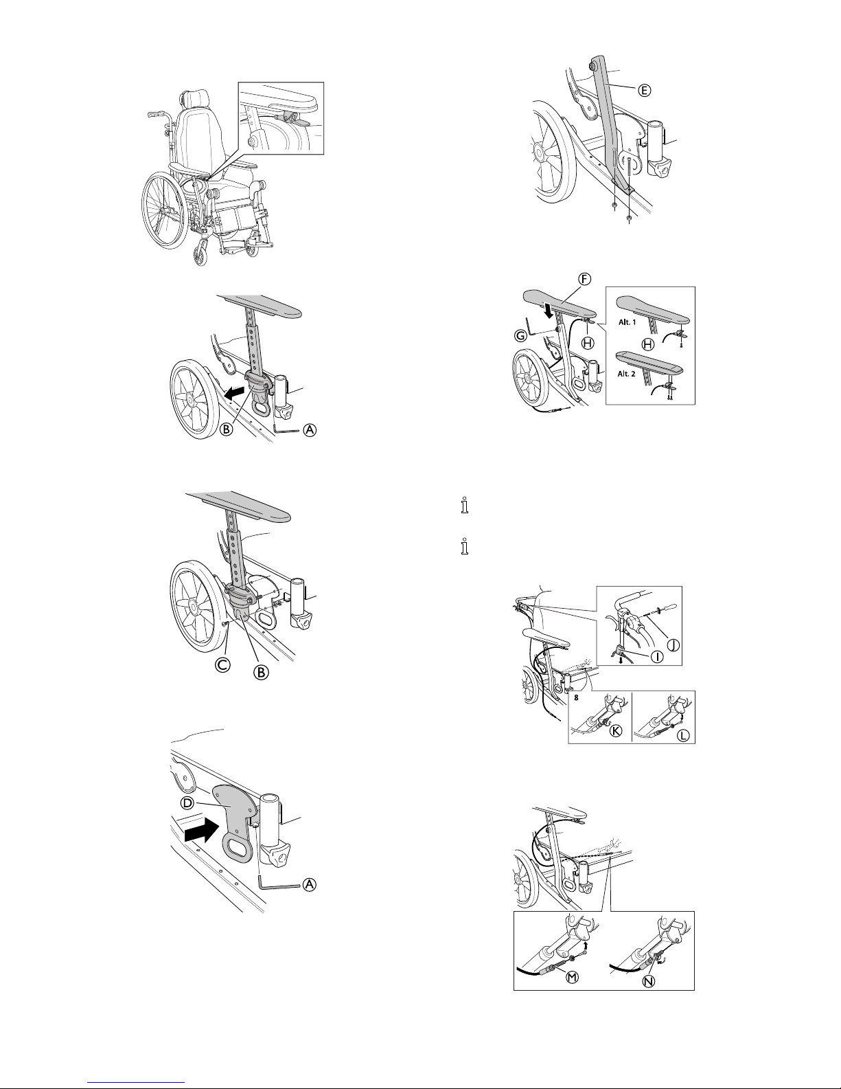
2.8Mountingtheusermaneuveredtilt
Dahlia 45
1.
A
B
LoosenthescrewtothearmrestwidthadjustmentA.Pullthe
armrestattachmentBoutwards.
2.
B
C
LoosenthescrewCtothearmrestattachmentBandremove
thearmrest.
3.
A
D
PushthetransportattachmentDbackinplaceandtightenthe
screwA.
4.
E
MountthearmrestattachmenttubefortheuseroperatedtiltE
ontheframeandtightenthescrews.
5.
Alt. 1
Alt. 2
F
G
H
H
RemovethearmrestpadFfromthestandardarmrest
attachmenttubeandplaceitinthenewarmresttubeE.Tighten
thescrewG.MounttheleverfortheuseroperatedtiltH
belowthearmrestpadinthefrontofthepad.Tightenthe
screw/screws.
Placethewirebetweenthearmrestpoleandtheside
rest.
Oneortwoattachmentscrewsareuseddependingon
thethicknessofthearmrestpad.
6.
8
I
J
K
L
LoosenthescrewJinordertoremovetheleverforthehand
operatedtiltI.Loosenthenuttothebrakewireforthetilt
handleKandremovethewireL.
7.
M
N
AttachthewireoftheuseroperatedtiltMandtightenthenutN.
81572308-B
Assembly
2.9Mountingthefootoperatedtilt
1.
B
A
MountthefootoperatedtiltAonthebackframeofthe
wheelchair.TightenthescrewB.
Thefootoperatedtiltisalwaysmountedontheright
side.
2.
D
C
E
F
LoosenthescrewCinordertoremovetheleverforthehand
operatedtiltD.Loosenthenuttothebrakewireforthetilt
handleEandremovethewireF.
3.
H
G
AttachthewireofthefootoperatedtiltGandtightenthenutH.
2.10Reducingtiltand/orbackrestrecline
Dependingontherearwheelsizewhenthewheelchairisordered
withalowseattofloorheight,reductionbushingsareaddedtothe
tiltand/orreclinefunctioninsomecombinations.Thisisbecause
theremaybeaconflictbetweentheseatframeandtherearwheel
attachmentwhentiltingorrecliningthechair.Thismeansthatthe
operatingrangeofthegaspistonisreducedinordertoavoiddamage
tocertainpartswhentiltingorrecliningthewheelchair.Oneormore
reductionbushingscanbeused,eachreductionbushingreducesthe
tilting/recliningrangewith10º.Thismeansthatifthetilt/reclinehave
arangeof1–30º,therangewillbereducedto1–20ºbyaddingone
reductionbushingtothegaspiston.FortheDahlia30ºversion,the
reductionbushingscanbeusedtoreduceboththetiltandtherecline
range.FortheDahlia45ºversion,thereductionbushingswillreduce
thereclinerangewith10ºor20ºandthereductionblockswillreduce
theseattiltrangefrom45ºto30º.
CAUTION!
Riskofdamage
Removingthereductionbushingscouldcausedamageto
thewheelchairinsomepositions.
–Becarefulwhentilting/recliningthechairifthe
reductionbushingsareremoved.Readtheinstructions
concerninglimitationareasandhowtoavoidthem.
Seesection:“Troubleshooting”formoreinformation.
2.10.1Mountingofthetilt/reclinereductionbushing
Thereductionbushingscanbeusedbothfortheseattilt
andthebackrestreclineonDahlia30ºandforthebackrest
reclinereductiononDahlia45º.
A
A
1.MountthereductionbushingAonthegaspistonrodbymanually
pressingitontothetube.
2.RemovethereductionbushingAbymanuallytwistingitfrom
thegaspistonrod.
Whenusingonebushing,thetilt/reclinereductionis10�,
withtwobushings,thetilt/reclinereductionis20�.
2.10.2Mountingthetiltreductionblock
B
C
1.PlacethereductionblockAinthesliderattachmentBonthe
seatframe.
2.FastenthescrewCandtighten.
3.Repeattheprocedurewiththesecondblock.
Withthesereductionblocksmounted,thetiltlimitis30�.
1572308-B9
Dahlia®30/45
2.11Repositioningthebackrestjoint
Thewidthextensionspacerscanbeusedwhenthereisneed
forawiderbackrestbar.Thespacerswilladdanextra25
mmspaceoneachside.
A
B
C
1.LoosenthethreescrewsAontheoutsideoftheseatframe.
Tools:5mmallenkey
2.InserttheplasticspacersBbetweenthebackrestattachment
Candtheseatframe.
3.RetightenthethreescrewsA(10Nm).
4.Repeattheprocedureontheoppositeside.
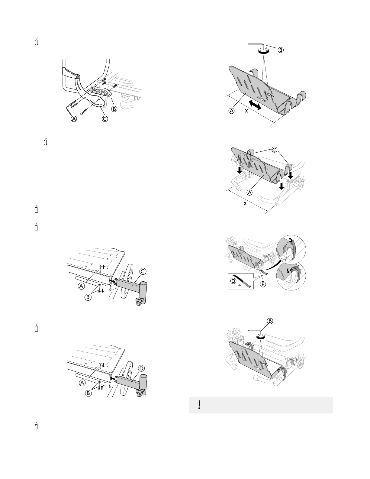
2.12Mountingthelegrestattachmentfor
highposition
Withthehighpositionlegrestattachment,thefixationofthe
legrestwillbe5cmhigher.
Thehighpositionlegrestattachmentisrecommendedfor
userswithaheightof185cmandtaller.
1.
A
B
C
RemovetheupperscrewAandthelowerscrewandwasherB.
RemovetheordinarylegrestattachmentC.
Tools:Screwdriver(PH2)forscrewA,allenkey5mmfor
screwB.
2.
D
B
A
MountthehighlegrestattachmentDintheseatframe.Re-insert
theupperscrewAandthelowerscrewandwasherB.
Re-tightenthescrews.
Tools:Screwdriver(PH2)forscrewA,allenkey5mmfor
screwB.
2.13Mountingtheaccessorytray
1.
X
A
B
LoosenthescrewsBoftheaccessorytrayAandadjustthe
width.
2.
X
A
C
MounttheaccessorytrayAonthechassis,thehooksCshould
beplacedontheframe.
3.
4x
E
D
SecuretheaccessorytraywiththeattachmentstrapsD.Thread
thestrapsthroughtheslotEandwrapthemaroundthehooks.
Securetheattachmentstrapsfirmly.
4.
B
Re-tightenthescrewsBtofixatethewidth.
Theaccessorytraywillbeinstable
–Alwayssecurethetraywithallfourattachmentstraps.
101572308-B
Assembly
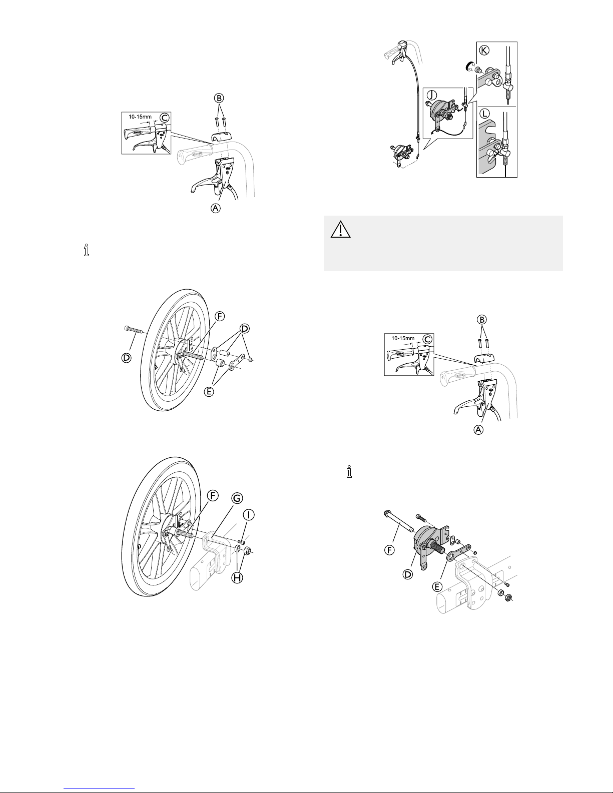
2.14Mountingthedrumbrake
2.14.1Drumbrakefor16”wheels
1.
A
B
C
MounttheleverfortheassistantmaneuvereddrumbrakeAon
thepushhandleandattachthescrewsB.
Thedistancebetweenthehandleandtheleverforthe
assistantmaneuvereddrumbrakemustbe10—15mm
C.
2.
D
E
F
D
MountthescrewfortheattachmentwasherDinthewheelwith
drumbrake.MounttheattachmentwasherandthesocketEon
therearwheelaxleF.
3.
G
F
H
I
MounttherearwheelaxleFintheattachmentGontheframe.
AttachthenutsHandthescrewI.
4.
J
K
L
Mountthewirehookfromthebrakehandleinthewireholder
J.MountthewireintheattachmentwasherKandplacethe
wireinthelowernotchonthebrakeL.
WARNING!
Riskofinjury
Poorbrakeeffect
–Checkthebrakeeffectaftermountingoradjustingthe
brake.
2.14.2Drumbrakefor22–24”
1.
A
B
C
MountthehandlefortheassistantmaneuvereddrumbrakeA
onthepushhandleandattachthescrewsB.
Thedistancebetweenthehandleandthehandleforthe
assistantmaneuvereddrumbrakemustbe10—15mm
C.
2.
D
E
F
MountthedrumbrakeD,theattachmentwasherEandthe
rearwheelaxleFontheframe.
3.
1572308-B
11
 Loading...