

Invacare Comfort-Mate Extra / Comfort-Mate Extra Base, Comfort-Mate Extra Comfort-Mat Installation And Operating Instructions Manual
Comfort-Mate Extra / Comfort-Mate Extra Base
Assembly, Installation and Operating Instructions
SAVE THESE INSTRUCTIONS
NOTE: Check all parts for shipping damage. In case of
damage, DO NOT use. Contact Carrier/Invacare for further instruction.
SAFETY SUMMARY
The following recommendations are made for the safe
and proper installation of the Comfort Mate Extra/
Comfort Mate Extra Base.
GENERAL WARNINGS
DO NOT install this equipment without first reading and understanding this instruction sheet. If you
are unable to understand the W arnings, Cautions
and Instructions, contact a healthcare professional, dealer or technical personnel if applicable
before attempting to install this equipment - otherwise, injury or damage may occur.
INSTALLATION WARNINGS
After ANY adjustments, repair or service and BEFORE use, make sure that all attaching hardware
is tightened securely.
USER WARNINGS
Skin condition should be checked frequently after the installation of any new seat.
IMPORTANT INFORMATION
The best way to avoid problems related to pressure sores
is to understand their causes and your role in a skin management program. The Comfort-Mate Extra Cushion and
Base are NOT designed for prevention of pressure sores.
Your therapist and physician should be consulted if you
have questions regarding individual limitations and needs.
As your needs become more complex, the seat evaluation becomes more important.
All seats should be selected carefully. Working with your
therapist, and physician is the best way to assure that a
seat choice matches your individual needs.
INTRODUCTION
Comfort-Mate Extra Cushion
The Comfort-Mate Extra is designed to provide comfort
and support with features such as molded contour shaping, dual layer foam, and water resistant coating.
Cushion Cover
The outer cover is made from a water repellant fabric to
protect the foam. The cover bottom is fabricated from a
waterproof, non-skid fabric. Regular cleaning and inspection of the cover is recommended. Refer to
SPECTION AND CLEANING in this instruction sheet.
SEAT IN-
ATTACHING/REMOVING CUSHION
TO/FROM SEATING SURFACE
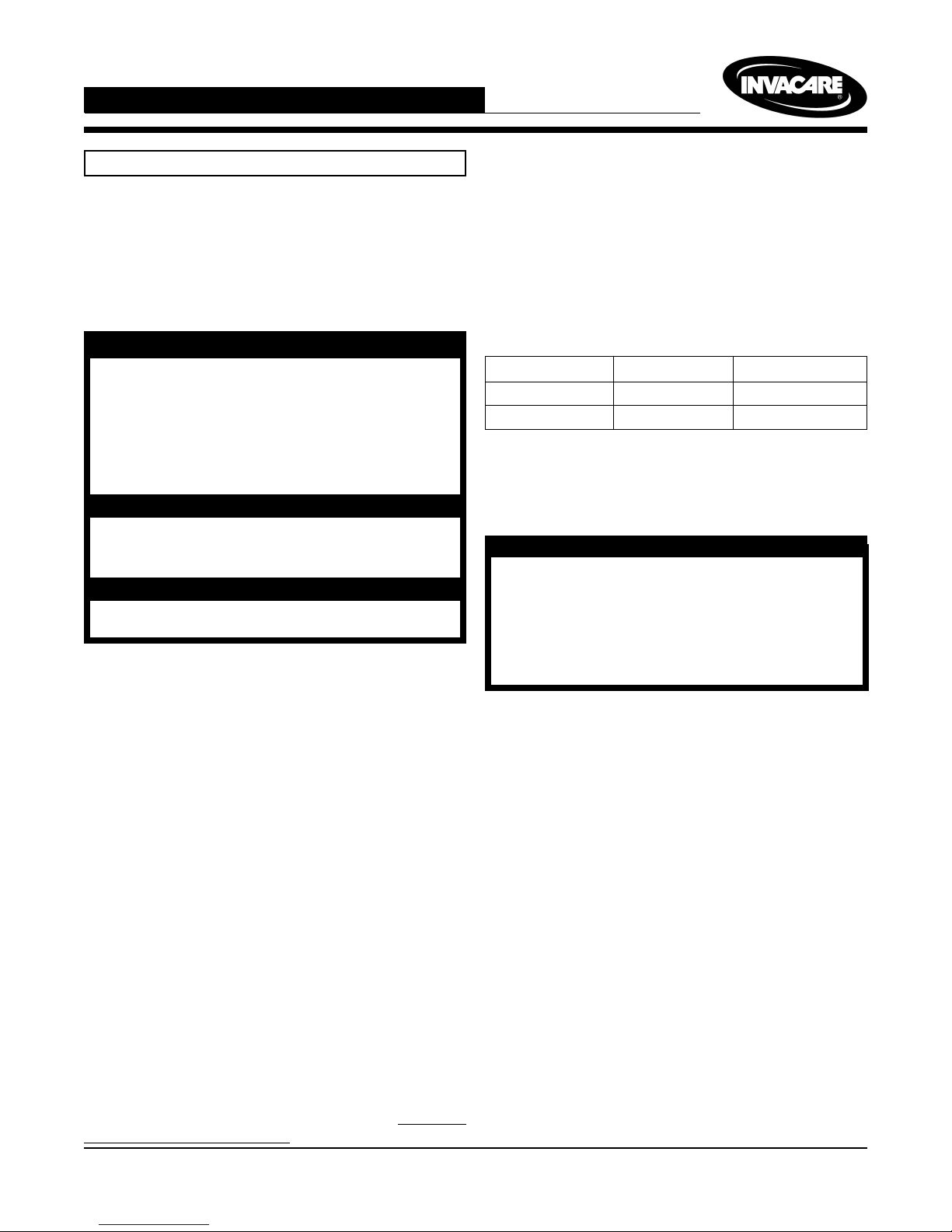
(FIGURE 1)
The cushion attaches to the wheelchair seating surface
using hook and loop fastening strips. The bottom of the
cushion cover is equipped with loop fastening strips. Attached to the loop fastening strips are double sided hook
fastening strips. Refer to the chart below to determine the
number of hook and loop fastening strips per cushion.
Cushion Width Loop Strips Hook Strips
14 - 19 inches 32
20 - 22 inches 42
NOTE: To remove the seat from a seating surface, reverse the following procedures.
NOTE: The seating surface can be one (1) of the following: Seat upholstery, drop base or seat pan.
WARNING
Make sure the hook and loop fastening strips are
securely attached to the seating surface and to
the seat BEFORE using. If the seating surface does
NOT have hook or loop fastening strips, use caution when transferring in and out of the wheelchair otherwise the cushion may shift.
1. Determine whether the wheelchair seating surface
has hook or loop fastening strips.
2. Perform one (1) of the following:
If the wheelchair seating surface has:
A. LOOP FASTENING STRIPS - verify that the
double sided hook fastening strips are securely
attached to the loop fastening strips on the bottom of the cushion.
B. HOOK FASTENING STRIPS - remove the double
sided hook fastening strips from the cushion.
C. NO HOOK OR LOOP FASTENING STRIPS -
remove the double sided hook fastening strips
from the bottom of the cushion.
NOTE: The zipper on the cushion should face the back
of the chair.
3. Align the front edge of the cushion with the front
edge of the seating surface.
4. Place the cushion on the wheelchair seating surface. If necessary make sure that the hook and loop
fastening strips are securely connected.
1
Zipper Faces
Back of Chair
Seat
Front of Seat
Loop Portion of
Fastening Strip
(Attached To
Seat)
Double Sided
Hook Portion of
Fastening Strip
Seating Surface
Front of
Cushion
Lines
up with
the
Front
Edge of
Seating
Surface
FIGURE 1- A TTACHING/ REMOVING
SEA T TO/FROM SEATING SURFACE
ATTACHING/ADJUSTING THE
CUSHION/BASE MOUNTING
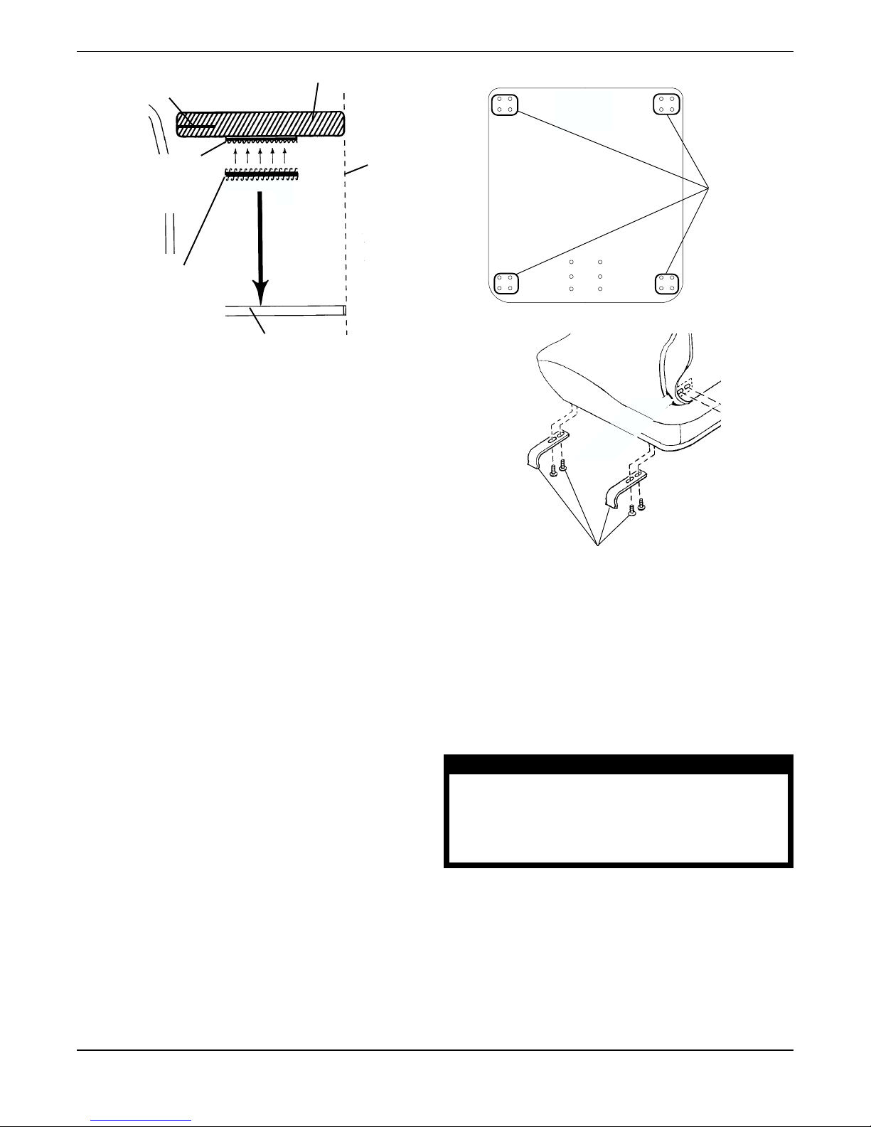
HOOKS TO BASE (FIGURE 2)
NOTE: Refer to FIGURE 2 in this instruction sheet for
mounting hook locations.
1. For minimal width adjustment, loosen the mounting screws and adjust the hooks in or out and
retighten the mounting screws.
2. For front-to-back position adjustment:
A. Remove the mounting screws that secure the
mounting hooks to the seat.
B. Adjust the mounting hooks to desired mount-
ing position.
C. Reinsert the mounting screws. Securely
tighten.
Mounting
Hook
Locations
Rear of Seat
Mounting Hooks and Screws
FIGURE 2- A TT ACHING/ ADJUSTING THE
CUSHION / MOUNTING HOOKS TO THE BASE
SEAT INSPECTION AND CLEANING
Inspection
NOTE: In order to ensure that the cushion is working as
designed, inspection and cleaning of the cushion on a
regular basis is necessary.
3. If all attachments and adjustments are complete,
zip the back cover closed.
WARNING
DO NOT continue to use this product if deformation, corrosion, breakage , wear and/or compression is discovered. Corrective maintenance can
be performed at or arranged through your equipment supplier.
1. Once a week, visually inspect all parts, including
hardware, upholstery materials, foams (if accessible),
and plastics for deformation, corrosion, breakage,
wear and/or compression.
Cleaning
1. Perform one (1) of the following Once a week:
2
 Loading...