

Invacare Celt Plus Maintenance And Spares Parts Manual
Invacare
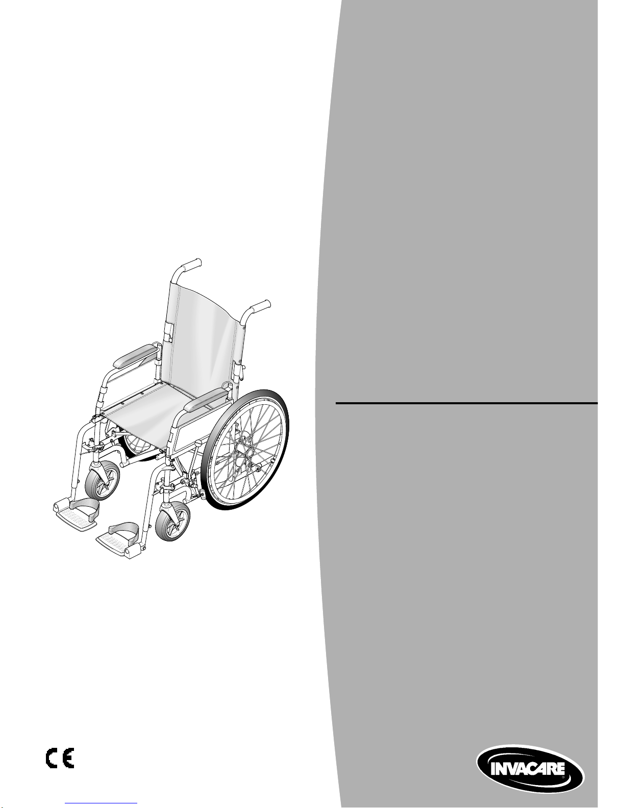
Celt Plus Chair
Maintenance and
Spares Parts Manual

11/03
Prelims ii
CELT PLUS
Contents Page
Chapter 1 Introduction
Introduction ..................................................................................................... 1.3
Policy................................................................................................................ 1.5
Technical Details.............................................................................................1.5
Types ................................................................................................................ 1.5
Chapter 2 Maintenance
Scope ............................................................................................................... 2.3
Inspection ........................................................................................................ 2.5
T ools.................................................................................................................2.5
Removing/Replacing Backrest Canvas......................................................... 2.7
Removing/Replacing An Armrest Assembly.............................................. 2.11
Removing/Replacing Main Wheel Assemblies........................................... 2.15
Removing/Replacing A Brake Assembly.................................................... 2.21
Removing/Replacing A Castor Wheel Assembly ....................................... 2.23
Removing/Replacing A Swing/Detachable Footrest Assembly ............... 2.25
Removing/Replacing Seat Canvas .............................................................. 2.27
Chapter 3 Illustrated Parts Catalogue
General............................................................................................................. 3.3
Ordering Information ...................................................................................... 3.3
CELT Wheelchair Assembly.......................................................................... 3.5
Fixed and Folding Backrest Assemblies ...................................................... 3.7
Reclining Backrest Assembly...................................................................... 3.11
Full Armrest Assemblies with Standard and Contoured Armpad ........... 3.15
Adjustable Armrest and Sports Armrest Assemblies............................... 3.17
Main Wheel Assemblies................................................................................3.19
Brake Assembly ............................................................................................ 3.23
Castor Wheel Assemblies ............................................................................ 3.25
Swing/Detachable Footrest Assemblies..................................................... 3.27
Seat Assembly .............................................................................................. 3.33
Optional Extras - Set Back Adaptor ............................................................ 3.37
Optional Extras - Seat to Ground Seat Canvas.......................................... 3.39
Optional Extras - Headrest........................................................................... 3.41

Page 1.111/03
INTRODUCTION
Chapter 1
Introduction
Page 1.2
11/03
CELT PLUS
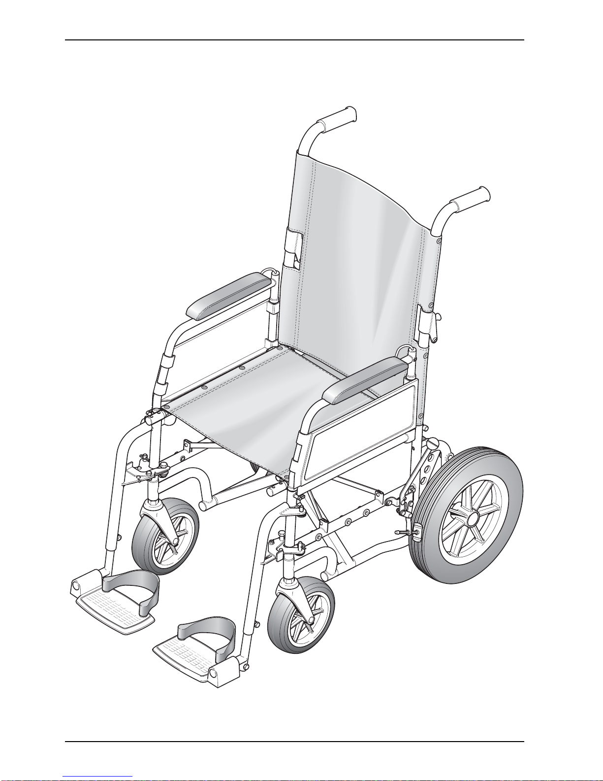
Figure 1.0 CELT Wheelchair with Transit Wheels

Page 1.311/03
INTRODUCTION
Introduction
1 This manual provides basic details to enable the CELT Wheelchair to be maintained. It is not intended to be
a comprehensive maintenance guide/policy, but is intended for use by competent personnel to enable the
chair to be adequately maintained.
2 The manual is split into the following chapters:
Chapter 2 Detailing assemblies that are maintainable and the relevant procedures.
Chapter 3 Detailing parts that are available to enable the maintenance in Chapter 2 to be complied with.
3 For Customer Service enquires, repairs, servicing and spares, contact INVACARE Ltd. at the address below
and quote all the details as indicated in paragraphs 6 and 7.
4 INVACARE Ltd.
South Road
Bridgend Industrial Estate
Bridgend
Mid-Glamorgan
CF31 3PY
Tel No: 01656 647327
Fax No: 01656 649016
5 Quote the following details at all times:
5.1 Part Number
5.2 Description
5.3 Quantity required
6 For certain orders the following should also be quoted:
6.1 Serial or batch number
6.2 End user
Page 1.4
11/03
CELT PLUS
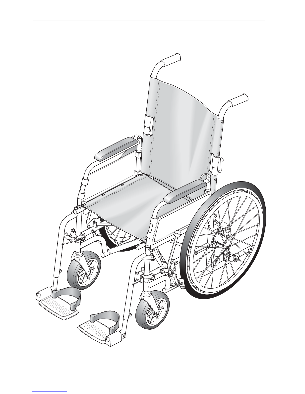
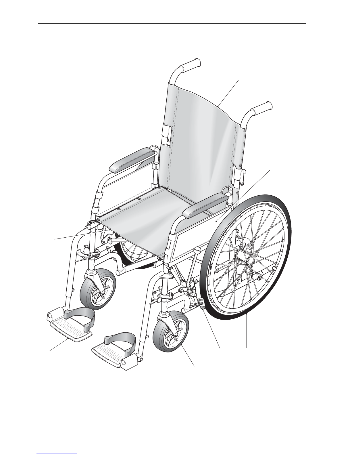
Figure 1.0 CELT Wheelchair with Self Propelling Wheels

Page 1.511/03
INTRODUCTION
Policy
7 INVACARE Ltd. repair policy is as follows:
Repairs to ANY component other than those detailed in Chapter 2 are not covered. Repairs to ANY metal
work is not generally permitted without express permission of INVACARE Ltd. ALL fasteners i.e. bolts,
Nyloc nuts, and any fastener showing damage MUST be renewed.
Failure to comply with the above absolves INVACARE Ltd. of liability.
☞ Note: Certain components will require removal to carry out maintenance. With the exception of
fasteners, these components should be refitted.
Technical Details
9 The following data applies to the CELT.
9.1 Available seat widths:
13" to 19" increments.
9.2 Chair depth available (adjusted using a spigot tube):
15", 16" and 17" (other sizes on application).
9.3 Seat to ground height:
19" (standard),17" and 21".
9.4 Wheel types available:
315mm diameter (Transit) and 20", 22" and 24" Self Propelling (Standard and QR).
9.5 Maximum user weight:
20 stone (127 kg), transit and pneumatic self propelling wheel.
18 stone (114.5 kg), solid self propelling wheel.
9.6 Backrest type:
Fixed 3°, 10°, 15° and 20°. Other options are folding and reclining.
9.7 Chair finish:
Polyester powdered coat (Black).
9.8 Transit weight of chair:
Approximately 17kgs (dependant on configuration and seat size).
Types
Options
10 The chair is available in various user defined optional types. For further details refer to
INVACARE Ltd. for details and acceptable combinations.

Page 1.6
11/03
CELT PLUS
LEFT BLANK INTENTIONALLY

11/03 Page 2.1
MAINTENANCE
Chapter 2
Maintenance
Page 2.2 11/03
CELT PLUS
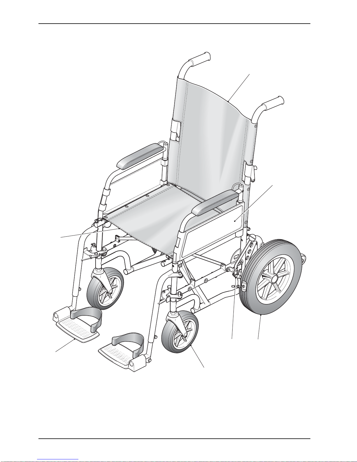
Figure 2.0.1 General Arrangement of Chair
1 Backrest 5 Castor wheel assembly
2 Armrest assembly 6 Swing/detachable footrest
3 Rear wheels 7 Seat
4 Brake assembly
1
6
7
2
43
5

11/03 Page 2.3
MAINTENANCE
Scope
1 This chapter details the removal and/or replacement procedures required for the following assemblies and/or
items. It is not intended to be a strict policy of maintenance but should be used as a guide only.
2 The assemblies covered (refer to Fig 2.0) are as follows:
Section Assembly Page
2.1 Backrest Canvas/Pushhandles 2.7
2.2 Armrest Assemblies 2.11
2.3 Rear Wheel Assemblies 2.15
2.4 Brake Assembly 2.21
2.5 Castor Wheel Assemblies 2.23
2.6 Swing/Detachable Footrest Assemblies 2.25
2.7 Seat Canvas and Chassis 2.27
3 For the tools required refer to the list of tools detailed in paragraph 12. Any special tooling and/or torque
requirements will be referred to within the relevant text.
4 General engineering practices and safe working practices must be adhered to at all times.
5 For further information on the assemblies contained within this chapter, contact Customer Services,
INVACARE Ltd., (refer to address in chapter 1) quoting the following details:
5.1 Part Number
5.2 Description
5.3 Quantity required
6 For certain orders the following should also be quoted:
6.1 Serial or batch number
6.2 End user
7 For any ordering or spares procurement, contact INVACARE Ltd., (refer to address in Chapter1) quoting the
details in paragraphs 5 and 6.
Page 2.4 11/03
CELT PLUS
CHAPTER 2.0
Figure 2.0.2 General Arrangement of Chair
1 Backrest 5 Castor wheel assembly
2 Armrest assembly 6 Swing/detachable footrest
3 Rear wheels 7 Seat
4 Brake assembly
1
6
7
2
43
5

11/03 Page 2.5
MAINTENANCE
Inspection
8 In general, a weekly visual check will meet all the inspection requirements.
9 Ensure that the following are checked:
9.1 Fabric is undamaged and has no signs of sagging.
9.2 The footrest is correctly fitted and latched.
9.3 Both armrests are securely fitted in place.
9.4 Brake mechanism operates freely and, when locked, the chair does not move.
9.5 Footplates and heel slings are undamaged and are correctly fitted.
9.6 Tyres are in good order and the wheels are not damaged.
9.7 If stabilisers are fitted, they are firmly locked in place.
9.8 Check that quick release spindle releases and locks correctly.
10 Check the finish of the chair for any damage.
☞ Note: Some finishes are unique to the chair. Check with INVACARE Ltd. for details.
11 Check that all bungs/plugs and handgrips are fitted and undamaged.
Tools
12 The following list details the basic tools required to carry out the maintenance procedures detailed in the following
sub-chapters.
12.1 Pliers
12.2 Drills (Metric and Imperial)
12.3 Spanners (Metric and Imperial)
12.4 Pozidriv screwdriver
12.5 Thin flat bladed screwdriver
12.6 Adjustable spanner
12.7 Torque wrench (20 to 40 lbf.ft rating)
12.8 Set of Allen keys (Metric and Imperial)
12.9 Protected jaw grips
12.10 Nylon mallet
12.11 Pop rivet gun
☞ Note: The above list is not exhaustive.
Page 2.6 11/03
CELT PLUS
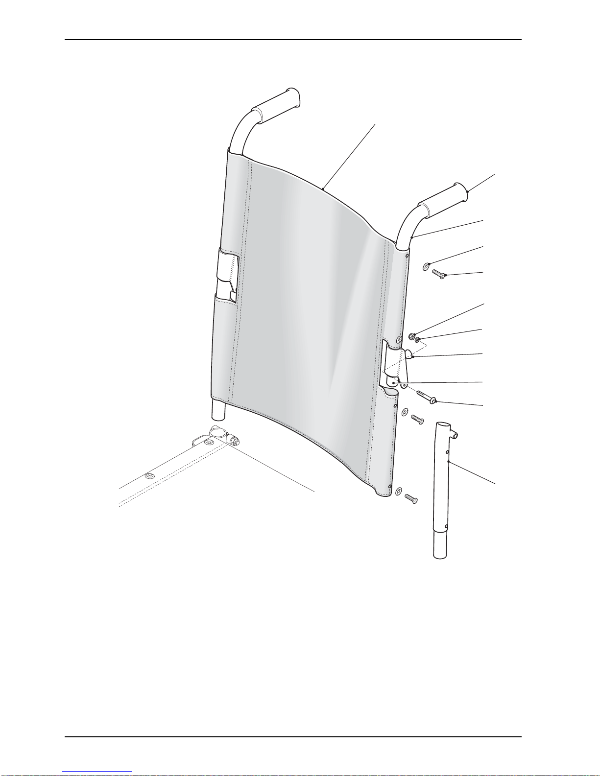
Figure 2.1.1 Folding Backrest Assembly
1 Backrest canvas 6 Plunger knob
2 Handgrips 7 Plunger
3 Push handle L/H 8 Hex head bolt
4 Cup washer 9 Nyloc nut
5 Pozi head screw 10 Washer
11 Lower half back frame tube
3
1
2
9
6
7
10
8
11
4
5

11/03 Page 2.7
MAINTENANCE
2.1 Removing/Replacing Backrest Canvas/Pushhandles
General
1 Check the (Fig 2.1.1) Backrest Canvas (1) and Push Handle (3) for any defects, (refer to paragraphs 4 and
5). If any defects are observed then refer to paragraphs 6 to 10 for maintenance.
2 Ensure that the push handle locks securely and that the locking mechanism functions correctly.
Tools
3 Refer to the tool list at the beginning of this Chapter.
Inspection
4 Inspect on a weekly basis for the following:
4.1 No signs of sagging, stretching or excessive wear in the Canvas (1).
4.2 No evidence of fraying, especially around the fastener points.
4.3 Pozidriv Head Screws (5) not missing and are tight.
4.4 Cup Washers (4) not missing and are tight.
5 Inspect the locking mechanism for the following:
5.1 Levers are not deformed or damaged.
5.2 Locks safely when the Push Handle (3) is in the upright position.
5.3 Not excessively stiff to operate (action should be smooth and positive).
Removal of the backrest canvas/pushhandles
6 To remove the Foldable Backrest (Fig 2.1.1) Canvas (1) proceed as follows:
6.1 Release the Plunger Knob (6) and fold the Push Handle (3) down.
6.2 Unscrew and remove the four Pozidriv Head Screws (5) and Cup Washers (4).
6.3 Unscrew and remove the two Bolts (8), Nyloc Nuts (9) and Plain Washers (10).
6.4 Unscrew and remove the two Plunger Knobs (6).
6.5 Slide the Backrest Canvas (1) off the Push Handle (3).
6.6 Slide the Backrest Canvas (1) off the lower half of the Back Frame (11).
7 To remove the canvas from the fixed backrest (Fig 2.1.2) proceed as follows:
7.1 Release the plunger operated lock in both rear vertical frame tubes and pull the complete backrest
out of the chassis.
7.2 Remove the pozihead screws (4) and washers (3) from both sides of the Backrest Tube (5) and
slide the canvas (6) off the backrest frame.
Page 2.8 11/03
CELT PLUS
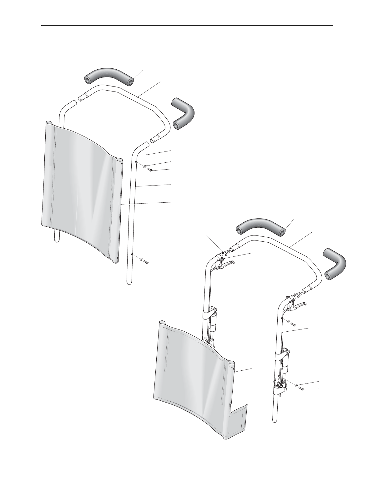
1 Neoprene grip 5 Pozihead screw
2 Push handle bar 6 Canvas
3 Back rest frame 7 Spring clip
4 Washer 8 Screw
Figure 2.1.3 Reclining Backrest
Figure 2.1.2 Fixed Backrest
1 Neoprene grip 4 Pozihead screw
2 Push handle bar 5 Fixed backrest tube
3 Washer 6 Canvas
1
2
3
5
6
4
3
1
7
2
8
4
3
6
5

11/03 Page 2.9
MAINTENANCE
8 To remove the canvas from the reclining backrest (Fig 2.1.3) proceed as follows:
8.1 Remove the Push Handle Bar (2) from the Backrest Frame (3) by depressing the Spring Clips (7).
☞ Note: It may be necessary to use pliers or a similar tool to extract the Spring Clips.
8.2 Remove the Pozi head screws (5) and washers (4) from the Backrest Frame tube (3).
8.3 Release the Canvas (6) by pulling apart the Velcro seal from the canvas.
8.4 Remove the canvas by sliding it off the Backrest Frame.
Replacing the backrest canvas
9 To replace the backrest canvas is the reverse of the removal, however ensure the following:
9.1 New Nyloc nuts are fitted.
9.2 The securing points are undamaged.
9.3 New cup washers are fitted as required.
9.4 That the backrest canvas is stretched evenly and is taut.
9.5 New Spring Clips are fitted in the Push Handle bar as required.
Page 2.10 11/03
CELT PLUS
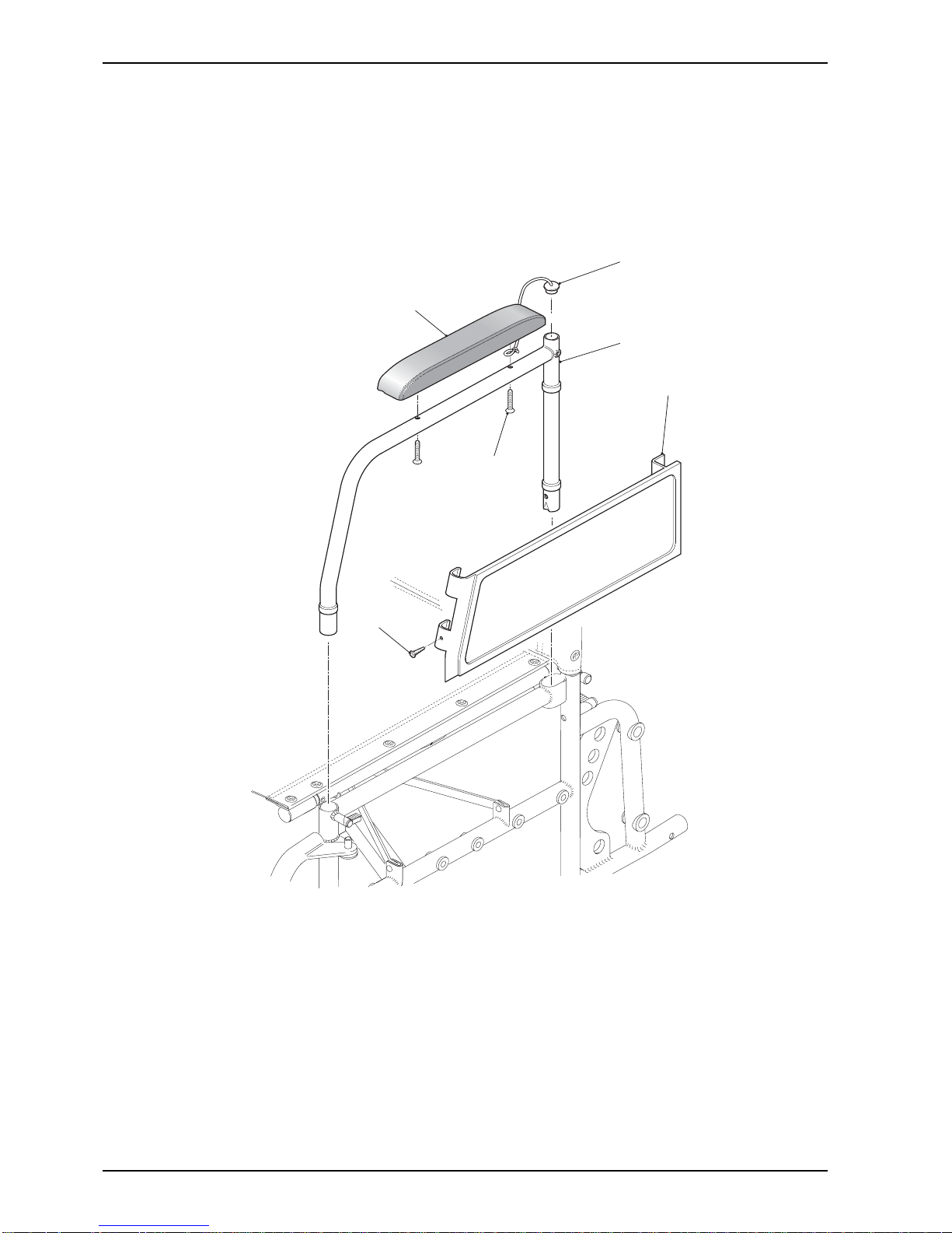
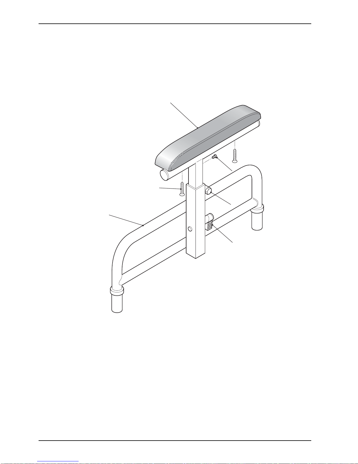
Figure 2.2.1 Armrest Assembly
5
6
2
3
4
1
1 Armpad
2 Sealing plug
3 Armrest frame
4 Armrest panel
5 Countersunk screw
6 Self tapping screw

11/03 Page 2.11
MAINTENANCE
2.2 Removing/Replacing An Armrest Assembly
General
☞ Note: The armrest assembly consists of a Armpad (1), Armrest Panel (4) and an Armrest Frame (3).
1 Check the armrest assembly for any defects (refer to paragraph 4). If any defects are observed then refer to
paragraphs 5 to 10 for maintenance details and to Chapter 3 for parts information.
2 The armrest can be renewed as either:
2.1 A complete assembly or
2.2 Armrest Panel and Armpad can be renewed as separate items.
Tools
3 Refer to the tool list at the beginning of this Chapter.
Inspection
4 Inspect on a weekly basis for the following:
4.1 Armrest Frame, Armrest Panel and finish are undamaged.
4.2 Armrest Pad is secure, not excessively worn and free of damage. Replace if necessary.
4.3 Replace missing fixing screws and tighten as required.
4.4 Armrest lock in side frame front tube engages and releases effectively.
4.5 Standard Armrest (Fig 2.2.1) - Check that the armrest panel is firmly in place and not bent or
damaged.
4.6 Adjustable Armrest (Fig 2.2.2) - Check smooth operation of height adjustment including Armrest
Cam lock.
Removing An Armrest Assembly
☞ Note: For ease of maintenance the armrest assembly can be replaced as a complete assembly.
5 To remove the Armrest assembly proceed as follows:
5.1 Release the armrest plunger lock in the side frame front tube and pull the armrest assembly out of the
chassis.
5.2 Adjustable Armrest (Fig 2.2.2) - Slacken the Clamp Bolt (5) and nut on the centre guide tube,
release the Armrest Cam lock (4) and pull the armrest out of the Armrest Frame.
6 To remove individual components of the armrest assembly proceed as follows:
6.1 Support the Armrest Frame (3) using a soft jawed vice and carry out the following procedures:
7 Removing the Armrest Pad (Fig 2.2.1) (1).
7.1 Unscrew and remove the two Screws (5). (Item 2 on adjustable armrest).
7.2 Remove the Armpad from the Armrest Frame.
8 Removing an Armrest Panel.
Page 2.12 11/03
CELT PLUS
Figure 2.2.2 Adjustable Armrest Assembly
1 Armpad
2 Countersunk screws
3 Armrest frame
4 Armrest cam lock
5 Bolt
6 Self tapping screw
1
3
6
5
4
2
☞
Note: Adjustable Armrest is available as an
option only on 315 (12 1/2") wheels.

11/03 Page 2.13
MAINTENANCE
8.1 Unscrew self tapping screw (6) from front of armrest.
8.2 Unclip the Armrest Panel (5) from the Armrest Frame (3) by pushing it horizontally in the direction of
the front of the chair and remove it.
Replacing Armrest Components
9 To replace the Armrest assembly or any of the components of the Armrest assembly is the reverse of the
removal; however ensure the following:
9.1 The Armrest Panel is flush fitting to the Frame.
9.2 Sealing Plugs are undamaged when replaced.
Page 2.14 11/03
CELT PLUS
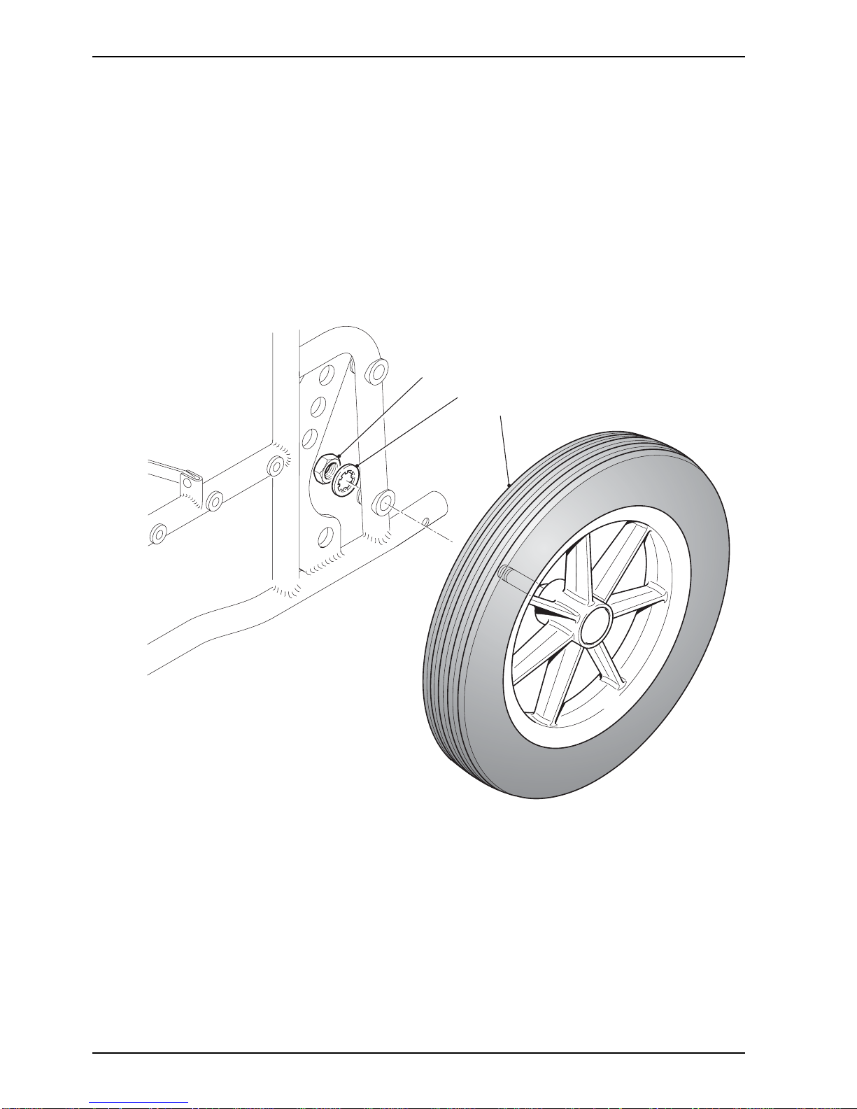
Figure 2.3.1 Rear Wheel Assembly
1 Wheel locknut 3 Rear wheel
2 Washer
2
1
3

11/03 Page 2.15
MAINTENANCE
2.3.1 Removing/Replacing Rear Transit Wheel Assemblies
General
☞ Note: This chair can be fitted with the following wheel types:
(a) Transit style, 315 mm solid or pneumatic.
(b) A 20 in, 22 in or 24 in diameter wheel with hand rim and Quick Release (Q.R.) hub,
solid or pneumatic tyres.
1 Check the wheel assembly for any defects (refer to paragraph 5). If any defects are observed then refer to
paragraphs 6 to 11 for maintenance details and to Chapter 3 for parts.
2 The main wheel assembly can be renewed as a complete assembly.
Tools
3 Refer to the tool list at the beginning of this Chapter.
3.1 A torque wrench of 25 lbf.ft rating is required.
Inspection
4 Inspect on a weekly basis for the following:
4.1 Damage to either wheel or tyre.
4.2 When the wheel assembly is allowed to free wheel that no binding, grating noise or
unconcentric rotation are present.
4.3 Wheel rim and spokes are undamaged.
4.4 If fitted, the hand rim is undamaged.
4.5 Excessive bearing rock.
Removing A Transit Wheel Assembly
5 To remove a transit wheel (3) (refer to Fig 2.3.1) proceed as follows:
5.1 Raise and support the chair so the damaged wheel is free of the ground.
5.2 Using a suitable size spanner grip the nut located behind the wheel hub.
5.3 Using the torque wrench, unscrew and remove the wheel locknut (1) and washer (2).
5.4 Slide the wheel (3) free from its location on the frame.
Replacing A Main Wheel Assembly
CAUTION: Apply Loctite 242 to the thread of the wheel shaft and ensure that the transit wheel
locknut is tightened to a torque of 25 lbf.ft.
☞ Note: Refer to section 2.3.1 for further information on configuration details.
6 Replacing the main wheel assemblies is the reverse of the removal.
Page 2.16 11/03
CELT PLUS
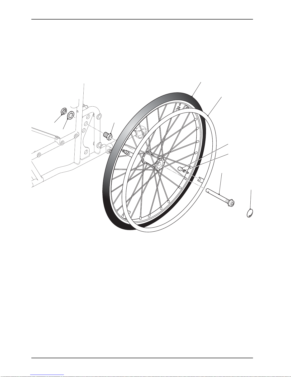
Figure 2.3.2 Self-Propelling Wheel Assemblies
1 Locking nut
2 Washer
3 Mounting bush
4 Tyre
5 Hand rim
6 Black nut cover
7 Nut
8 QR spindle
9 N/A
10 N/A
11 Plastic hub cap
3
2
1
10
8
11
9
6
7
4
5
 Loading...