

Invacare Bora XTR, Spectra XTR Service Manual
Invacare®Bora®/Spectra®XTR
Series
enPowerWheelchair
ServiceManual
DEALER:Keepthismanual.
TheproceduresinthismanualMUSTbeperformedbyaqualied
technician.

©2019InvacareCorporation
Allrightsreserved.Republication,duplicationormodicationinwholeorinpartisprohibitedwithoutpriorwritten
permissionfromInvacare.T rademarksareidentiedby™and®.AlltrademarksareownedbyorlicensedtoInvacare
Corporationoritssubsidiariesunlessotherwisenoted.

Contents
1General.........................................4
1.1Introduction..................................4
1.2AboutThisManual.............................4
1.3GeneralInformation............................4
1.4NotesonShipping..............................4
1.5SymbolsinThisManual..........................4
1.6ImagesinThisManual..........................4
2Safety..........................................5
2.1SafetyandFittingInstructions.....................5
3Hygiene.........................................7
3.1HandlingofReturnedUsedProducts................7
4Setup...........................................8
4.1AdjustingSeatingPosition........................8
4.2AdjustingLowerLegLength.......................8
4.3AdjustingSeatDepth............................8
4.4AdjustingCentreofGravityoftheSeat..............8
4.4.1ModuliteSeat..............................9
5Service..........................................13
5.1GeneralWarningInformationonInstallationWork......13
5.2Troubleshooting...............................13
5.2.1OperationalFaults...........................13
5.2.2DriveFaultDiagnosis.........................13
5.3TighteningT orques.............................14
5.4ServicePlan(OnceaY ear)........................14
5.5OverviewComponents..........................16
5.5.1MobilityDeviceWithDetachableSeat............16
5.5.2MobilityDeviceWithLifterAndTiltModule........16
5.6Chassis......................................17
5.6.1ReplacingKerbClimber(L-ShapeLever)...........17
5.6.2ReplacingKerbClimber(T -ShapeLever)...........18
5.7DriveComponents..............................18
5.7.1PreparingReplacementofDriveComponents.......18
5.7.2OverviewMotor/GearboxUnit..................19
5.7.3ReplacingSwingArm.........................19
5.7.4ReplacingMotor-GearboxUnit..................20
5.7.5ReplacingorRotatingMotor-GearboxUnitSealing
Ring.....................................21
5.7.6ReplacingMotor-GearboxCoupling...............21
5.7.7ReplacingCarbonBrushes.....................22
5.7.8ReplacingEngagingTurnKnob..................22
5.8Wheels......................................23
5.8.1TyrePressure...............................23
5.8.2TyreTypes.................................23
5.8.3SpecicTighteningTorques....................24
5.8.4OverviewofPowerWheelchairModelsandWheel
Types....................................24
5.8.5ReplacingDriveWheel(1-BoltInstallation).........26
5.8.6Replacingdrivewheelhub.....................26
5.8.7ReplacingCastorWheelonDouble-SidedFork......27
5.8.8ReplacingTyres.............................28
5.8.9ReplacingSteeringHeadBearingsonCastors.......29
5.8.10Replacingmanualwheellock..................30
5.8.11Replacinganti-tippingmechanismwithscrew.....31
5.8.12Replacinganti-tippingmechanismwithlocking
spring....................................31
5.8.13Replacingdefectivelockingspring...............31
5.9Shrouds.....................................32
5.9.1ReplacingFrontShroud.......................32
5.9.2Replacingfender............................32
5.10Controls....................................32
5.10.1ReplacingPowerModule.....................32
5.10.2ReplacingG-TracSensor......................33
5.10.3ReplacingOperatingHourCounter..............34
5.10.4ReplacingConnectingCableofOperatingHour
Counter..................................34
5.10.5Updatingsoftware..........................35
5.11Batteries....................................35
5.11.1RemovingBatteryBoxes......................36
5.11.2ReplacingBatteries..........................36
5.11.3RemovingBatteriesfromBatteryTray............37
5.11.4GeneralInstructionsonHandlingtheBatteries.....38
5.11.5HowtoHandleDamagedBatteriesCorrectly.......38
5.11.6MainFuse................................39
5.11.7CheckingCables............................40
5.12LightingUnit.................................40
5.12.1Replacingheadlight(LEDlight).................40
5.12.2ReplacingFrontLampHolder(LEDLight)..........41
5.12.3ReplacingRearLight(LEDLight)................41
5.13Seating.....................................41
5.13.1ReplacingTiltTube..........................41
5.13.2Replacingactuator—poweredtiltwithxed
pivotpoint................................42
5.13.3ReplacingSeatHeightAdapter.................43
6Accessories......................................44
6.1AccessoriesList................................44
Invacare®Bora®/Spectra®XTRSeries
1General
1.1Introduction
Thisdocumentcontainsimportantinformationabout
assembly,adjustmentandadvancedmaintenanceofthe
product.Toensuresafetywhenhandlingtheproduct,read
thisdocumentandtheusermanualcarefullyandfollow
thesafetyinstructions.
FindtheusermanualonInvacare’swebsiteorcontact
yourInvacarerepresentative.Seeaddressesattheend
ofthisdocument.
Invacarereservestherighttoalterproductspecications
withoutfurthernotice.
Beforereadingthisdocument,makesureyouhavethe
latestversion.YoundthelatestversionasaPDFonthe
Invacarewebsite.
Forpre-saleanduserinformation,seetheusermanual.
Formoreinformationabouttheproduct,forexample
productsafetynoticesandproductrecalls,contactyour
Invacarerepresentative.Seeaddressesattheendofthis
document.
1.2AboutThisManual
•ThismanualreferstocongurationswithModulite
seatsystem.Olderspecications(forexample,Flex2
seatsystem)havebeendescribedinrevision15of
thisservicemanual.
•Forseatsystems,seethecorrespondingmanual.
•ForShark,DX,DX2,VR2orR-Netelectronics,see
revision15ofthisservicemanual.
•ForLiNXelectronics,seeLiNXServiceManual.
1.3GeneralInformation
•Serviceandmaintenanceworkmustbecarriedout
takingthisservicemanualintoaccount.
•Itisimperativethatyouobservesafetyinformation.
•Informationaboutoperationoraboutgeneral
maintenanceandcareworkonthemobilitydevice
shouldbetakenfromservicemanual.
•Y oucanndinformationaboutorderingspareparts
inthesparepartscatalogue.
•SparepartsmustmatchoriginalInvacareparts.
Onlyusesparepartswhichhavebeenapprovedby
Invacare.
•Wereservetherighttomakeanyalterationsonthe
groundsoftechnicalimprovements.
•Formoreinformationabouttheproduct,forexample
productsafetynoticesandproductrecalls,contact
yourlocalInvacarerepresentative.Foraddressand
websiteseebackpageofthismanual.
•Themobilitydevicemayonlybemaintainedand
overhauledbyqualiedpersonnel.
•Theminimumrequirementforservicetechniciansis
suitabletraining,suchasinthecycleororthopedic
mechanicselds,orsufcientlylong-termjob
experience.
–Experienceintheuseofelectricalmeasuring
equipment(multimeters)isalsoarequirement.
–SpecialInvacaretrainingisrecommended.
•Alterationstothemobilitydevicewhichoccur
asaresultofincorrectlyorimproperlyexecuted
maintenanceoroverhaulworkleadtotheexclusion
ofallliabilityonthesideofInvacare.
•Ifyouhaveanyproblemsorquestionscontactyour
provider .
1.4NotesonShipping
•Ifthemobilitydevicehastobeshippedbacktothe
manufacturerformajorrepairs,youshouldalways
usetheoriginalpackagingfortransport.
•Pleaseattachaprecisedescriptionofthefault.
1.5SymbolsinThisManual
Inthismanual,hazardstatementsareindicatedby
symbols.Thesymbolsareaccompaniedbyasignalword
thatindicatestheseverityoftherisk.
WARNING
Indicatesahazardoussituationthatcould
resultinseriousinjuryordeathifitisnot
avoided.
CAUTION
Indicatesahazardoussituationthatcould
resultinminororslightinjuryifitisnot
avoided.
IMPORTANT
Indicatesahazardoussituationthatcould
resultindamagetopropertyifitisnot
avoided.
Givesusefultips,recommendationsand
informationforefcient,trouble-freeuse.
ThisproductcomplieswithDirective
93/42/EECconcerningmedicaldevices.The
launchdateofthisproductisstatedintheCE
declarationofconformity.
Thissymbolidentiesalistofvarioustools,
componentsanditemswhichyouwillneedin
ordertocarryoutcertainwork.
1.6ImagesinThisManual
Thedetailedimagesinthismanualaregivenmarksto
identifyvariouscomponents.Componentmarksintext
andoperationalinstructionsalwaysrelatetotheimage
directlyabove.
4
1528338-Q

Safety
2Safety
2.1SafetyandFittingInstructions
Thesesafetyinstructionsareintendedtopreventaccidents
atwork,anditisimperativethattheyareobserved.
Beforeanyinspectionorrepairwork
•Readandobservethisrepairmanualandthe
associatedusermanual.
•Observetheminimumrequirementsforcarryingout
thework(see1.3GeneralInformation,page4).
PersonalSafetyEquipment
Safetyshoes
Themobilitydevice,andsomeofitscomponents,arevery
heavy.Thesepartscanresultininjuriestothefeetifthey
areallowedtodrop.
•Wearstandardizedsafetyshoesduringallwork.
Eyeprotection
Itispossiblethatbatteryacidcanbedischargedwhen
workingondefectivebatteriesorwhenhandlingbatteries
improperly.
•Alwaysweareyeprotectionwhenworkingonany
defectiveorpossiblydefectivebatteries.
Safetygloves
Itispossiblethatbatteryacidcanbedischargedwhen
workingondefectivebatteriesorwhenhandlingbatteries
improperly.
•Alwayswearacid-proofsafetygloveswhenworking
onanydefectiveorpossiblydefectivebatteries.
GeneralSafetyInformationandInformationAboutFitting
/Removal
DANGER!
RiskofDeath,SeriousInjury,orDamage
Lightedcigarettesdroppedontoanupholstered
seatingsystemcancauseareresultingin
death,seriousinjury ,ordamage.Mobility
deviceoccupantsareatparticularriskofdeath
orseriousinjuryfromtheseresandresulting
fumesbecausetheymaynothavetheabilityto
moveawayfromthemobilitydevice.
–DONOTsmokewhileusingthismobility
device.
WARNING!
RiskofSeriousInjuryorDamage
Storingorusingthemobilitydevicenearopen
ameorcombustibleproductscanresultin
seriousinjuryordamage.
–Avoidstoringorusingthemobilitydevice
nearopenameorcombustibleproducts.
CAUTION!
Riskofcrushing
Variouscomponentssuchasthedriveunit,
batteries,seatetcareveryheavy.Thisresults
ininjuryhazardstoyourhands.
–Notethehighweightofsomecomponents.
Thisappliesespeciallytotheremovalofdrive
units,batteriesandtheseat.
CAUTION!
Injuryhazardifthemobilitydevicestarts
movingunintentionallyduringrepairwork
–Switchthepowersupplyoff(ON/OFFkey).
–Engagethedrive.
–Beforeliftingup,securethemobilitydevice
byusingchockstoblockthewheels.
CAUTION!
Fireandburnhazardduetoelectrical
short-circuit
–Themobilitydevicemustbecompletely
switchedoffbeforeremovalof
voltage-carryingcomponents!Todo
this,removethebatteries.
–Avoidshort-circuitingthecontacts
whencarryingoutmeasurementson
voltage-carryingcomponents.
CAUTION!
Riskofburnsfromhotsurfacesonthemotor
–Allowthemotorstocooldownbefore
commencingworkonthem.
CAUTION!
Injuryhazardandriskofdamagetomobility
deviceduetoimproperorincomplete
maintenancework
–Useonlyundamagedtoolsingoodcondition.
–Somemovingpartsaremountedinsockets
withPTFEcoating(Teon™).Nevergrease
thesesockets!
–Neveruse"normal"nutsinsteadof
self-lockingnuts.
–Alwaysusecorrectly-dimensionedwashers
andspacers.
–Whenreassembling,alwaysreplaceanycable
tieswhichwerecutduringdismantling.
–Aftercompletingyourwork/beforerenewed
start-upofthemobilitydevice,checkall
connectionsfortighttting.
–Aftercompletingyourwork/beforerenewed
start-upofthemobilitydevice,checkallparts
forcorrectlocking.
–Onlyoperatethemobilitydevicewiththe
approvedtyrepressures(seetechnicaldata).
–Checkallelectricalcomponentsforcorrect
function.Notethatincorrectpolaritycan
resultindamagetothecontrolsystem.
–Alwayscarryoutatrialrunattheendof
yourwork.
CAUTION!
Riskofinjuryanddamagetoproperty ,ifthe
maximumspeedreductiononawheelchair
withalifterdoesnotfunctioncorrectly
Thewheelchair’scontrolunitmustreducethe
maximumpossiblespeedassoonasthelifter
israised.
–T estthemaximumspeedreductionfor
correctfunctionafteranymaintenancework
ormodicationstothewheelchair .
1528338-Q
5

Invacare®Bora®/Spectra®XTRSeries
CAUTION!
Anychangestothedriveprogramcanaffect
thedrivingcharacteristicsandthetipping
stabilityofthemobilitydevice
–Changestothedriveprogrammayonlybe
carriedoutbytrainedInvacareproviders.
–Invacaresuppliesallmobilitydeviceswitha
standarddriveprogramex-works.Invacare
canonlygiveawarrantyforsafemobility
devicedrivingbehavior-especiallytipping
stability-forthisstandarddriveprogram.
Markallcurrentsettingsforthemobilitydevice
(seat,armrests,backrestetc.),andtheassociated
cableconnectingplugs,beforedismantling.This
makesreassemblyeasier.Allplugsarettedwith
mechanicallockswhichpreventreleaseofthe
connectingplugsduringoperation.Toreleasethe
connectingplugsthesafetylocksmustbepressed
in.Whenreassemblingensurethatthesesafety
locksarecorrectlyengaged.
6
1528338-Q

3Hygiene
3.1HandlingofReturnedUsedProducts
Whenreconditioningorrepairingreturnedmobilitydevices:
•T akeprecautionsforyourselfandtheproduct.
•Useprotectionequipmentasspeciedlocally.
BeforeTransport(AccordingtoBiologicalAgentsOrdinance)
Treatproductaccordingtofollowingprocesssteps:
Hygiene
ProcessStepComponent
ApplicationConditioning
ManualcleaningSurfaceofuseddeviceBeforerepairor
reconditioning
DisinfectionSurfaceofuseddeviceBeforerepairor
reconditioning
*Invacareusesdetergent"Nücoseptspecial"1.5%inwaterml/ml
DisinfectionT ools
•Disposablewipes(eece)
•Brushestocleanareasdifculttoaccess
FurtherInformation
FormoreinformationcontactyourInvacareservicedepartment.
technique
Usesaturatedtowel
toapplycleaning
detergentandremove
residuesafterimpact.
Usesaturated
disinfectantwipes
andclean*thedevice
surface.
WorkStation
Cleaningand
disinfection
Cleaningand
disinfection
1528338-Q
7
Invacare®Bora®/Spectra®XTRSeries
4Setup
4.1AdjustingSeatingPosition
Toadaptthemobilitydeviceoptimallytotherequirements
oftheuser ,werecommendthatyouaskyourauthorised
Invacareprovidertoadjusttheseatdepthindividually.
Adaptingtheseattotheuser'sseatingpositiondepends
onwhichseathasbeentted,andshouldbecarriedout
inthefollowingsequence:
1.Adjustinglowerleglengthandseatdepth.See4.2
AdjustingLowerLegLength,page8.
2.Adjustingcentreofgravityofseatframe.See4.4
AdjustingCentreofGravityoftheSeat,page8.
3.Checkingthatcastorscanmovefreely.
4.Checkingthatwheelchairisstableandwillnottip
over .SeeChecktippingstability,page12.
5.Repetitionofsteps2to4,ifnecessary.
CAUTION!
Riskofinjuryaftertiltingofmobilitydevice
causedbyblockedcastors
–Alwayscheckseatdepthsettingsforboth
forwardandreversemovement.Makesure
thatcastorscanrotatefreelyandhave
notcontacttoanyxedmobilitydevice
component.
CAUTION!
Riskoftippingover
Anychangeintheseatingpositioncan
negativelyinuencethestabilityofthepower
wheelchair.
–Alwaysmakesurethatthewheelchairis
stableandwillnottipover ,afteradjusting
theseatingposition.
CAUTION!
Anychangestodriveprogramcanaffect
drivingcharacteristicsandtippingstabilityof
vehicle.
–Changestodriveprogrammayonlybecarried
outbytrainedInvacareproviders.
–Invacaresuppliesallmobilitydeviceswitha
standarddriveprogramex-works.Invacare
canonlygiveawarrantyforsafevehicle
drivingbehaviour-especiallytippingstability
-forthisstandarddriveprogram.
CAUTION!
RiskofCrushingtoHandsandFeet
Theseatisveryheavy.Riskofinjurytohands
andfeet.
–Payattentiontohandandfeet.
–Useproperliftingtechniques.
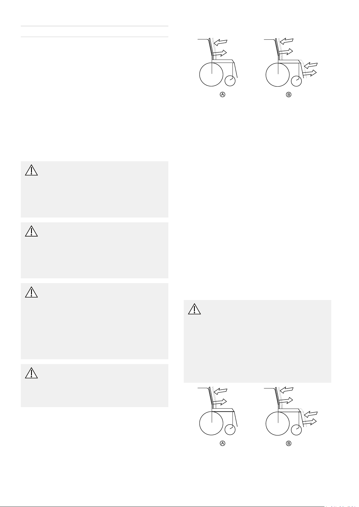
4.3AdjustingSeatDepth
Fig.4-1
A:Seatdepth
B:Centreofgravityoftheseat/seatposition
SeatdepthAcanbeadjustedbymovingbackrestin
relationtoseatsurface.
SeatSystems
Fordetailson
•Standardseat
•Flex2seat
•Firmseat
•Maxseat
refertorevision15ofthisservicemanual.
FordetailsonModuliteseatseebelow.
ModuliteSeat
Seatdepthcanbeadjustedbymovingbackrestinrelation
toseatsurface.Seeusermanual.Forseatdepthsettings,
seeSeatDepthSetting,page10.
4.4AdjustingCentreofGravityofthe Seat
Thecentreofgravityoftheseatcanbeadjustedby
mountingtheseatframefarthertowardsthefrontorthe
rearofthechassis.
CAUTION!
Theseatingsystemofthemobilitydeviceis
deliveredexworkswithastandardadjustment
ofcentreofgravity(CoG),whichmeets80
–90%ofuserrequirements.CoGcanbe
adjustedindividually.However ,anychange
inthisadjustmentsettingcannegatively
inuencethestabilityofthemobilitydevice.
–Youmustperformanindividualriskanalysis
everytimeyouchangethecentreofgravity
oftheseatingpositiontoensurethesafety
andstabilityofthemobilitydevice.
4.2AdjustingLowerLegLength
Invacareoffersarangeoflegrestswhichcanbeadjusted
individually.Seeusermanual.
8
Fig.4-2
A:Seatdepth
B:Centreofgravityoftheseat
1528338-Q
Setup
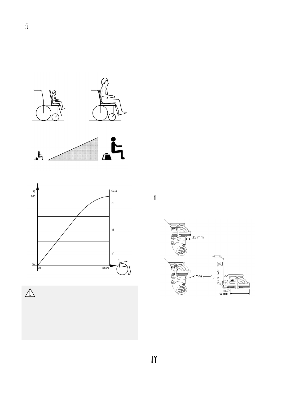
Theuserweightandseatdepthhavestrong
inuencesonthechoiceofthecentreofgravity
(CoG).Iftheuserisheavyandtheseatdepthis
greater ,thefocusshouldbethefartherback.For
bestpossibledrivingcharacteristicsofrear-wheel
drivemobilitydevice,theweightshouldbe
distributed:30–40%frontand60–70%rear.
Front-andcentre-wheeldrivesareuncriticalwith
regardtodistributionofuserweight.
Fig.4-3
•Flex2seat
•Firmseat
•Maxseat
refertorevision15ofthisservicemanual.
FordetailsonModuliteseat,seebelow.
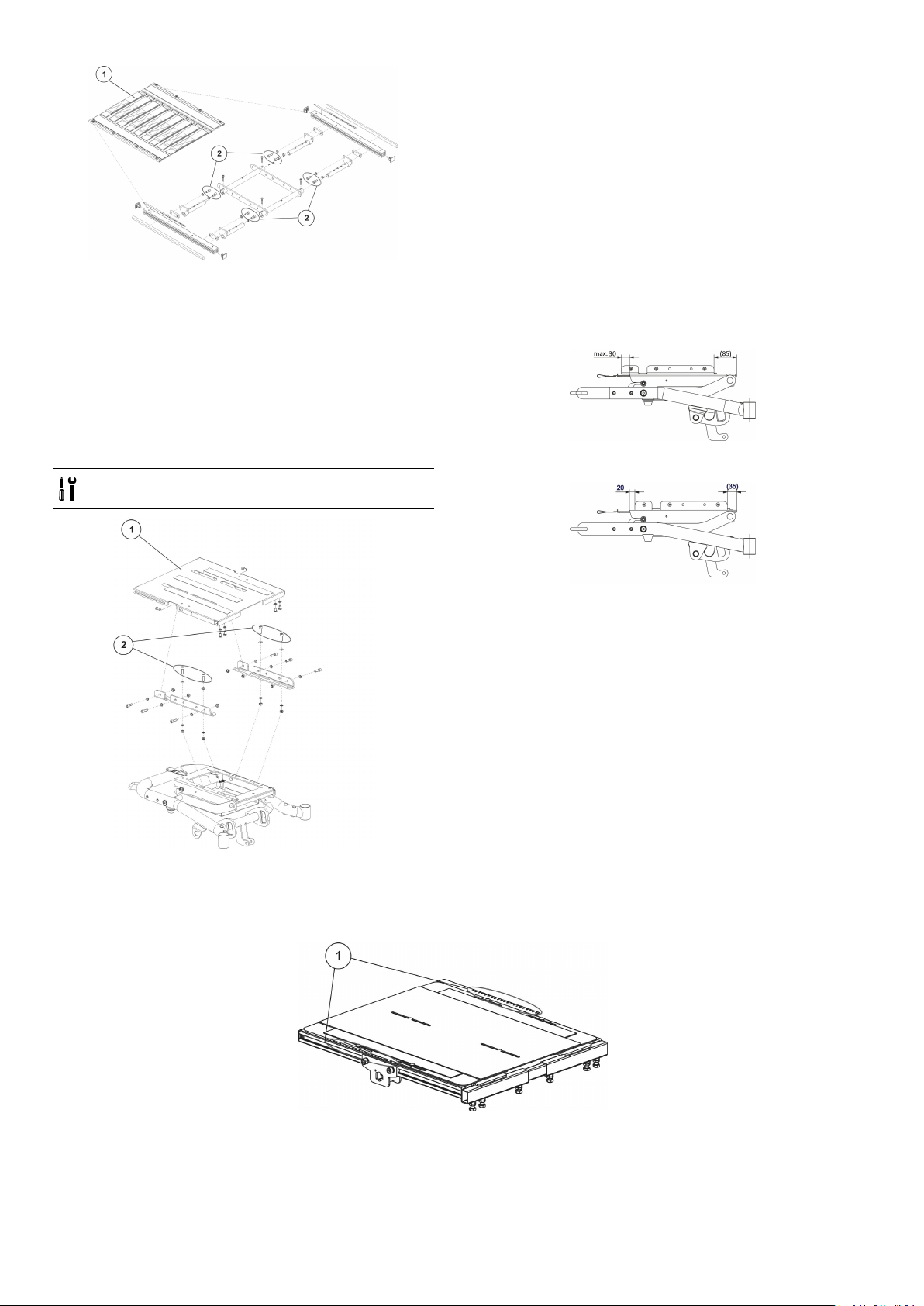
4.4.1ModuliteSeat
TheModuliteseatisavailableintwoversions:
•Adjustmentofthecentreofgravityviathelateral
prolesofthetelescopicseatframe(plateandstrap).
SeeTelescopicSeatFrame,page9.
•Adjustmentofthecentreofgravityviatheoblong
holesoftheseatadaptor(one-pieceseatplate).See
One-PieceSeatPlate,page10
Ifthemobilitydeviceisusedwithdrivelock-out,the
seatcentreofgravitycanbesafelymonitoredinthe
correspondingseatposition.
Drivelock-outisafeaturedesignedtopreventthe
wheelchairfrombeingdrivenaftertheseatingsystemhas
beentiltedbeyondthesafetotalanglerelativetothe
verticalposition.Thetotalanglecanbeanycombination
oftilt,reclineand/orsurfaceangle.Seetheusermanual
formoreinformationonthisfunction.Theseatposition
settingswithvariouscombinationsofseatdepth,seat
width,cushiontypeandbackreststylearedescribedin
SeatDepthSetting,page10.
•Placeawoodenblockunderthebackresttoavoid
collisionsbetweenframeandback.
.
Fig.4-4
CAUTION!
Riskofdamageduetocollisionsofthelegrests
withotherpartsofthemobilitydevice.
–Setlegreststosmallestanglebeforeadjusting
seatcentreofgravity.
–Payattentionwithadjustingtheseatcentre
ofgravitythatthelegrestsdonottouchany
otherpartsofthewheelchair .Thisensures
thatthelegrestscannotcollidewithother
partsofthewheelchair.
Ifthemobilitydeviceisusedwiththedrive
lock-out,variationstothevaluesstatedbelowcan
occur.SeeMountingPositionofSeatFrame,page
10andSeatDepthSetting,page10.
Fig.4-5
Thefrontedgeoftheseatframeproleshouldbelocated
35mminfrontofthesteeringheadsofthecastors.Ifyou
decreasethisvalue,makesurethat
•Y oudecreasetheseatdepthbythesamevalueand
•Therearenocollisionsbetweenthelegrestsandthe
castors.
SeatSystems
Fordetailson
•Standardseat
1528338-Q
TelescopicSeatFrame
•6mmAllenkey
9
Invacare®Bora®/Spectra®XTRSeries
1.Removeseatplate(1)orslingseat.SeeModulite
servicemanual,“ Adjustingseatwidth/backrestwidth”
chapter .
2.LoosenAllenscrews(2)infrontandrear ,leftandright
–DONOTremove.
3.Shiftpositionofseatframe.
4.Re-tightenscrews.
5.Installseatplateagain.
MountingPositionofSeatFrame
Fig.4-6
1.Removeseatplateorslingseat(1).SeeModulite
servicemanual,“ Adjustingseatwidth/backrestwidth”
chapter .
2.Loosenscrews(2)infrontandrear ,leftandright–
DONOTremove.
3.Shiftpositionofseat.
4.Re-tightenscrews.
5.Installseatplateorslingseat.
One-PieceSeatPlate
•6mmAllenkey
Thecentreofgravityoftheseatcanbeadjustedby
mountingtheseatframefarthertowardsthefrontorthe
rearontheseatsupport.SeeModuliteservicemanual.
Ifthemobilitydeviceisusedwithdrivelock-out,choose
differentscrewpositions,forexample:
Fig.4-8MountingPositionofSeatFramewithFlex3Backrestand
SeatDepth51cm
Fig.4-9MountingPositionofSeatFrameonSeatSupportWithout
DriveLock-Out
Fig.4-7Thispictureisanexample.
SeatDepthSetting
Adjusttheseatdepthusingtheprolescale(1)inaccordancewiththefollowingtable:
Fig.4-10
10
1528338-Q

Flex3Backrest/SeatPlates
Seatwidth38cm
Seatwidth43cm
Seatwidth48/53cm
Flex3Backrest/SlingSeat
Seatwidth38cm
Seatwidth43cm
Seatwidth48/53cm
ProlelengthSeatdepth
51cm41cm4.5
51cm46cm2
54.5cm51cm1
ProlelengthSeatdepth
51cm41cm
51cm46cm2.5
54.5cm51cm1.5
ProlelengthSeatdepth
51cm41cm
51cm46cm3
54.5cm51cm2
ProlelengthSeatdepth
51cm41cm3.5
51cm46cm1
54.5cm51cm0
ProlelengthSeatdepth
51cm41cm4
51cm46cm1.5
54.5cm51cm0.5
ProlelengthSeatdepth
51cm41cm4.5
51cm46cm2
54.5cm51cm1
Setup
Settingvalue/prolescale
Settingvalue/prolescale
5
Settingvalue/prolescale
5.5
Settingvalue/prolescale
Settingvalue/prolescale
Settingvalue/prolescale
Tension-AdjustableBackrest/SeatPlates
Seatwidth38/43/48/53
cm
ProlelengthSeatdepth
51cm41cm
51cm46cm
51cm51cm2.5
Tension-AdjustableBackrest/SlingSeat
Seatwidth38/43/48/53
cm
ProlelengthSeatdepth
51cm41cm6.5
51cm46cm4
51cm51cm1.5
MatrX(PB)/SeatPlates
Seatwidth38/43cm
ProlelengthSeatdepth
51cm41cm
51cm46cm
51cm51cm2.5
Settingvalue/prolescale
7.5
5
Settingvalue/prolescale
Settingvalue/prolescale
7
5
1528338-Q
11
Invacare®Bora®/Spectra®XTRSeries
Seatwidth48cm
ProlelengthSeatdepth
51cm41cm
51cm46cm
51cm51cm3
Seatwidth53cmnotoffered
MatrX(PB)/SlingSeat
Seatwidth38/43cm
ProlelengthSeatdepth
51cm41cm6
51cm46cm4
51cm51cm1
Seatwidth48cm(53cmis
notoffered)
ProlelengthSeatdepth
51cm41cm
51cm46cm4
51cm51cm1.5
Seatwidth53cmnotoffered
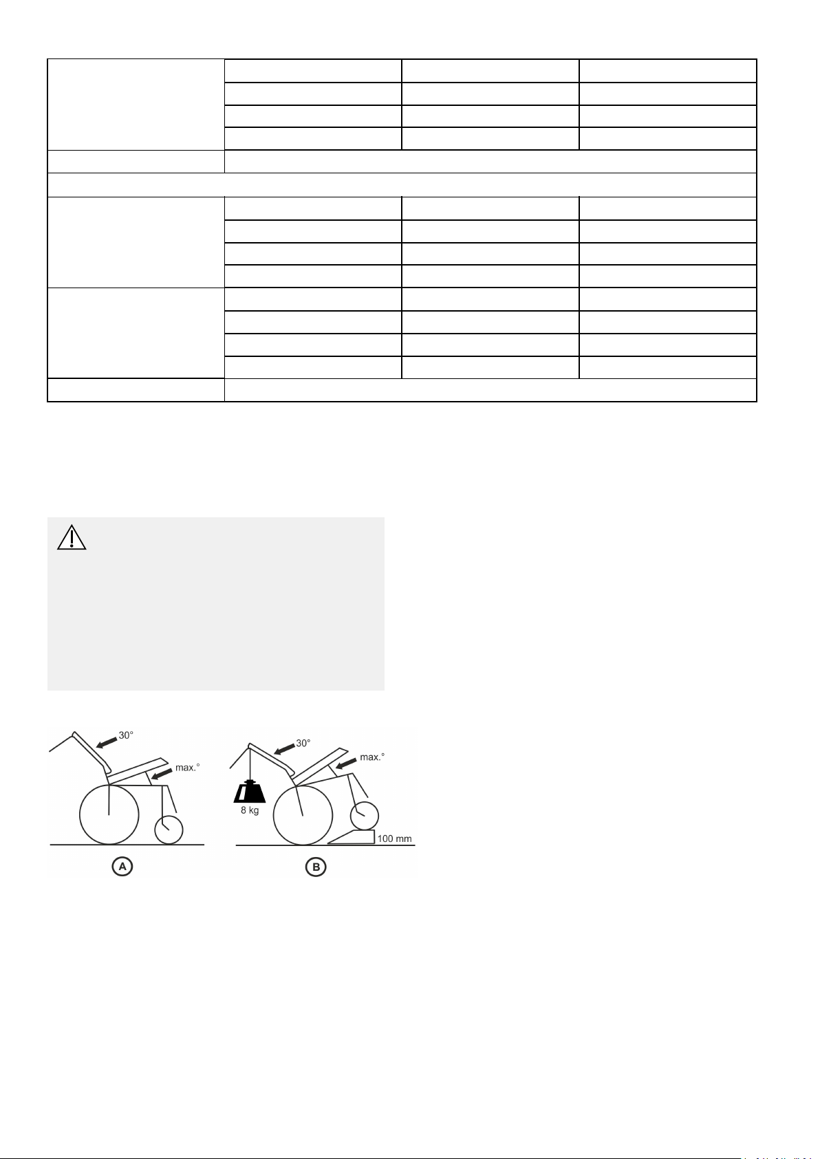
Checktippingstability
Anychangeinseatingpositioncannegativelyinuence
tippingstabilityofthepowerwheelchair .Forthisreason,
afteradjustingtheseatingposition,youshouldalways
verifytippingstabilityofmobilitydevice.
CAUTION!
Anychangestodriveprogramcanaffect
drivingcharacteristicsandtippingstabilityof
mobilitydevice.
–Changestodriveprogrammayonlybecarried
outbytrainedInvacare®specialistdealers.
–Invacare®suppliesallmobilitydeviceswitha
standarddriveprogramex-works.Invacare®
canonlygiveawarrantyforsafedriving
behaviour-especiallytippingstability-for
thisstandarddriveprogram.
Tippingstabilitycheck
Settingvalue/prolescale
7.5
5
Settingvalue/prolescale
Settingvalue/prolescale
7
3.Drivefrontwheelsofmobilitydeviceontoastep
about100mmhigh.Thiscanbedoneusingaramp,
forexample(illustrationB).
4.Makesurethatfrontwheelsarepointedbackwards
comparedtodirectionoftravel.
5.Attachareferenceweightof8kgtothepushbar
(illustrationB).
6.Verifythatmobilitydeviceisatmostinabalancedor
"oating"conditioninthisposition.Thismeansthat
frontwheelscanslightlylosecontactwithground,but
chairmustnottipbackontoitsanti-tipperwheels.If
mobilitydevicedoesnotfallbackontoitsanti-tipper
wheels,tippingstabilityisOK.Ifmobilitydevicefalls
backontoitsanti-tipperwheels,youmusteither:
•Shiftcenterofgravityfarenoughforwardthat
chairdoesnotfallontoanti-tipperwheelsor
•Installadaptor
7.Repeatstepsdescribedaboveaftereachmodication
toverifytippingstability.
1.Setfollowingangleonwheelchair:
•Recline30°
•Seattiltmax.
2.Allowusertodowninmobilitydeviceinasitting
positionthatistypicalforthem.
12
1528338-Q

Service
5Service
5.1GeneralWarningInformationon InstallationWork
CAUTION!
Riskofdamagetovehicle
Collisionscanbecausediftheadjustingwashers
areremovedduringttingworktothedrive
wheels.Adjustingwashersareoftentted
betweenthedriveshaftandthewheelhubto
evenouttolerances.Iftheseadjustingwashers
areremovedandnotreplacedagain,collisions
canbecaused.
–Alwaysreplacetheadjustingwashersexactly
astheywerebeforeyoustarteddismantling.
CAUTION!
Riskofinjuryanddamagetoproperty,if
themaximumspeedreductiononamobility
devicewithalifterdoesnotfunctioncorrectly
Themobilitydevice’ scontrolunitmustreduce
themaximumpossiblespeedassoonasthe
lifterisraised.
–T estthemaximumspeedreductionfor
correctfunctionafteranymaintenancework
ormodicationstothemobilitydevice.
5.2Troubleshooting
5.2.1OperationalFaults
Proceedasfollowsifyouhaveanyproblems:
1.Firstassessthepossiblecauseoftheproblemusing
thefollowingtable.
2.Checktheremotestatusdisplay.Evaluatetheash
errorcode.
3.Carryoutthenecessarychecksandrepairsas
recommendedinthefollowingtable.
Thevariouspowermodulescanbettedinconnection
withdifferentremotesinthemobilitydevice.Rectication
ofoperationalfaultsdependsonthepowermodule
tted.Thepowermodulesusedaredescribedinthe
correspondingcontrolsmanual.
Thetablesforrecticationofoperationalfaults
listedinthefollowingchaptersareonlyanexcerpt
fromtheoriginalmanufacturer'smanuals.Y oucan
obtaintheoriginalmanualsfromInvacare.
5.2.2DriveFaultDiagnosis
ProblemOthersymptomsPossiblecauseSolution
Mobilitydevicewill
notstart
Mobilitydevice
juddersindrivemode
Batteriesnotbeing
charged
Theremotestatus
displayilluminates
normallyandshows
anerrorcode.
Remotestatusdisplay
doesnotilluminate
Remotestatusdisplay
blinking
None
None
LEDsblinkingon
chargingunit
Drivemotors
disengaged
BatteriesdefectiveReplacebatteries
Completelydischarge
battery
Powersupplyto
remoteinterrupted
RemotedefectiveCheckcablesbetween
Variouscauses
Batteriesdefective
(unstablevoltage)
Drivemotor(s)
defective
BatteriesdefectiveReplacebatteries
ChargingunitdefectiveReplacechargingunitSeeusermanual
Documentation
EngagedrivemotorsSeecorresponding
remotemanual
See5.11Batteries,
page35
Pre-chargebatteriesSeeusermanual
Checkmainfuse
themodulesfor
looseconnectionsand
damage
AssesserrorcodeSeecorresponding
Replacebatteries
Replacemotor(s)
Replacecarbon
brushes
See5.11.6MainFuse,
page39
See5.11.7Checking
Cables,page40
remotemanual
See5.11Batteries,
page35
See5.7Drive
Components,page
18
See5.11Batteries,
page35
1528338-Q
13

Invacare®Bora®/Spectra®XTRSeries
ProblemOthersymptomsPossiblecauseSolution
Mobilitydeviceruns
None
RemotedefectiveReplaceremoteSeecorresponding
tooslowly
BatteriesdefectiveReplacebatteries
5.3TighteningTorques
CAUTION!
Riskofdamagetomobilitydevicedueto
improperlytightenedscrews,nutsorplastic
connections.
–Alwaystightenscrews,nutsetc.tothestated
tighteningtorque.
–Onlytightenscrewsornutswhicharenot
listedherengertight.
Thetighteningtorquesstatedinthefollowinglistare
basedonthethreaddiameterforthenutsandboltsfor
whichnospecicvalueshavebeendetermined.Allvalues
assumedryandde-greasedthreads.
5.4ServicePlan(OnceaYear)
Documentation
electronicsmanual
See5.11Batteries,
page35
ThreadTighteningT orquein
Nm±10%
M43Nm
M5
6Nm
M610Nm
M825Nm
M1049Nm
M1280Nm
M14120Nm
M16180Nm
CAUTION!
Riskofinjuryanddamagetoproperty,ifthemaximumspeedreductiononamobilitydevicewithalifterdoes
notfunctioncorrectly
Themobilitydevice’scontrolunitmustreducethemaximumpossiblespeedassoonasthelifterisraised.
–T estthemaximumspeedreductionforcorrectfunctionafteranymaintenanceworkormodications
tothemobilitydevice.
Component
Armrests
CheckRemedy
Riskofdamageto
armrests
Replaceshrouds,if
damaged
ArmrestxingsTightenscrews
Clothes-guard
Riskofdamageto
clothes-guards
Replaceclothes-guards,if
damaged
Clothes-guardxingsTightenscrews
SeatlockSeatlockdefectiveReplaceseatlock
TiltCheckSLretainerclipfor
correctt
Powerrecline(iftted)
Riskofdamagetobackrest
Seams
Fixing
Checkcable
ReplaceSLretainerclip,if
necessary
Replaceparts,ifdamaged
Tightenscrews
Replaceactuatorcable,if
necessary
Checkfunction
Frames(chassis)/battery
mounting
Checkxings,welded
seamsandbattery
mounting
Tightenscrews
Replacecomponents,if
necessary
Notes
14
1528338-Q

Service
Component
Wheelsuspensionand
wheels
Driveunits,coupling
mechanism
Legrests
Powerelevatinglegrests
(iftted)
Lighting(iftted)
Batteries
CheckRemedy
Checkdrivewheelsfor
tighttandsideplay
Checkcastorsfortightt,
oatandsideplay
Pneumatictyres(iftted)
Checkfunctionsindrive
andpushmodes
Checkcoupling
mechanism
Adjust,replacewheel
hubs
Replacewheels,wheel
forkorwheelbearings
Repairorreplace,if
damaged
Replacemotor ,if
necessary
Tightenscrews/nuts,
adjustorreplace,if
Notes
See
See
See5.8.8ReplacingTyres,
page28
necessary
Checkweldedseams,
interlocking,screws,
Tighten,replace,if
necessary
foot-plates
CheckcableReplacecable,ifnecessary
Checkcontacts
Checkfunctions
CheckcableReplacebulb,LEDsor
cable,ifnecessary
Checkfunction
Checkbatteriesfor
damage
Replacebatteries,if
necessary
See5.11Batteries,page
35
CheckbatteryvoltageChargebatteriesSeeusermanual
Checkcontactsand
terminals
Cleancontactsand
terminals
Seesafetyinformationin
•5.8.5Replacing
DriveWheel(1-Bolt
Installation),page26
•5.8.6Replacingdrive
wheelhub,page26
•5.8.7Replacing
CastorWheelon
Double-SidedFork,
page27
•5.8.9Replacing
SteeringHead
BearingsonCastors,
page29
•5.11Batteries,page
and
35
•5.11.5HowtoHandle
DamagedBatteries
Correctly,page38
BatteryboxChecklockingsystem,it
mustengagecompletely
Remote
Remote,statusdisplay
ashing
Fixings
Cablesandconnecting
plugs
Joystickfunction
1528338-Q
Replace,ifnecessary
Evaluateerror/ashcode
Checkxingsfortightt,
replace,ifnecessary
Checkconnectingplugs
fortightt,replace,if
necessary
Replacejoystick,if
necessary
Replaceremote,if
necessary
15
 Loading...