

Invacare Birdie, Birdie Plus User Manual
Invacare® Birdie
Invacare® Birdie
EN
User's Manual
FR
Manuel d'utilisation
ES
Manual del usuario
DE
Gebrauchsanweisung
NO
Brukervejledning
FI
Kaäyttöonje
NL
Gebruiksaanwijzing
DA
Brugermanual
SV
Bruksanvisning
IT
Manuale d'uso
PT
Manual de Utilização
TM
TM
Plus

EN
User's Manual 4
FR
ES
DE
NO
FI
NL
DA
SV
IT
PT
Manuel d'utilisation 20
Manual del usuario 36
Gebrauchsanweisung 52
Brukervejledning 68
Kaäyttöonje 84
Gebruiksaanwijzing 100
Brugermanual 116
Bruksanvisning 132
Manuale d'uso 148
Manual de Utilizaçao 164

UK
User's Manual
Stamp of the Distributor

Table of Contents
1. General ...............................................6
2. Main parts of the hoist ...................................8
3. Unpacking, assembly and disassembly of the hoist ..........9
4. Operating the hoist ....................................10
5. Emergency lowering, emergency lifting and emergency stop . 13
6. Accessories ..........................................14
7. Maintenance and cleaning ..............................14
8. Waste disposal ........................................15
9. Trouble-shooting ......................................16
10. Technical specifications ................................17
11. Symbols .............................................19

6
7
BirdieTM, Birdie
TM
Plus and BirdieTM Compact
Thank you for choosing Invacare®’s BirdieTM mobile hoist. Invacare®’s BirdieTM are especially designed
to lift the patient to and from wheelchairs, beds, toilets and oors. BirdieTM hoists offer easy handling and
increased comfort within the nursing sector. The design of BirdieTM provides a longer reach, wider leg
span and a wider lifting range.
The choice of either electrical or manual leg span combined with the large range of spreader bars and
slings available from Invacare®makes it easy to adjust the hoist for optimum patient care.
Throughout the entire production process, our materials and components are quality controlled by the
operators. A nal test is made when the product is fully assembled. If the product does not correspond to
the quality demands of Invacare®, it will not pass quality control.
In the event of a problem in connection with the delivered product, please contact your local
Invacare®supplier.
Invacare®will take no responsibility if the product is used or assembled in any way other than stated in
this user manual. Only accessories mentioned in this user manual may be used on the Birdie
TM
mobile
hoists. This product must only be operated by qualied staff who has received the necessary instruction
and training.
Please read this user manual carefully before you are using the mobile hoist.
1. General
TM
Birdie•
EEC
concerning medical devices.
TM
Birdie•
ISO 10535.
Control unit and motors have been approved according to EN 60601.•
TM
Birdie•
ISO 14971.
Control unit, motors and hand control are IPX4 protected.•
Lifting capacity: • Birdie
The hoist has an expected lifetime of 8 years.•
The hoist will not operate when in charge mode.•
Disconnect the charger from the hoist before moving or using the hoist. Make sure the mains cable is not
squeezed or damaged when assembly or disassembly of the hoist or when moving the hoist.
If the functions of the hoist change, please see the section “Maintenance and cleaning”.
This product must be serviced and maintained by qualied personnel.
, Birdie
, Birdie
, Birdie
TM
Plus and Birdie
TM
Plus and Birdie
TM
Plus and Birdie
TM
and Birdie
TM
Compact are CE-marked in accordance with directive 93/42/
TM
Compact have been tested and approved according to EN/
TM
Compact have undergone a risk analysis according to EN/
TM
Plus 170 kg, Birdie
TM
Compact 150 kg.
7
Please be aware of the following possible risks when using the hoists:
The hoist must be carefully supervised if the patient is a child.
Please note that it is more difficult to manoevre the hoist on carpeted or uneven/textured
surfaces as opposed to wooden or flat surfaces; this is due to the starting forces required to
initiate the movement that may create additional friction exerted on the castors.
It is recommended not to move the user with the jib at maximum height. Take great care
when moving the hoist on carpeted, wet, slippery, rough or uneven surfaces. Never use on
slopes.
Caution! Never attempt to lift a patient outside the base area of the hoist. When lifting a
patient from the floor, the patient must always be located between the two hoist legs,
and never outside this area. To avoid injury, utmost care must be taken when raising and
lowering a patient.
Invacare®accepts no liability for any use, change or assembly of the Birdie
and Birdie
TM
Compact hoists other than as stated in this user manual.
There is a risk of squeezing and entrapment during operation and transport of the hoist.
Never exceed the maximum recommended lifting capacity.
TM
, Birdie
TM
Plus
It is important that the cables do not become entrapped or jammed in moving parts and
castors during operation and transport.
Important! Invacare®recommend that operation of any mobile lifting equipment is carried
out by personnel with prior professional training in moving and handling techniques.
Always choose the sling design and size according to the patient’s weight, size and physical
ability.
Always ensure, that the sling is applied correctly. Never leave a patient in the sling
unattended.
Please ensure that the hoist is not exposed to water, as this can cause damage.
Locking pin must be located into the base position when transporting the hoist.
Failure to do so may cause injury during handling.
8
9
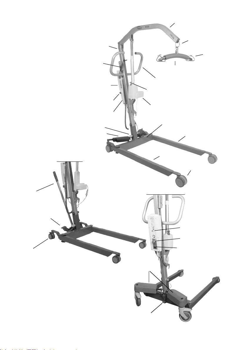
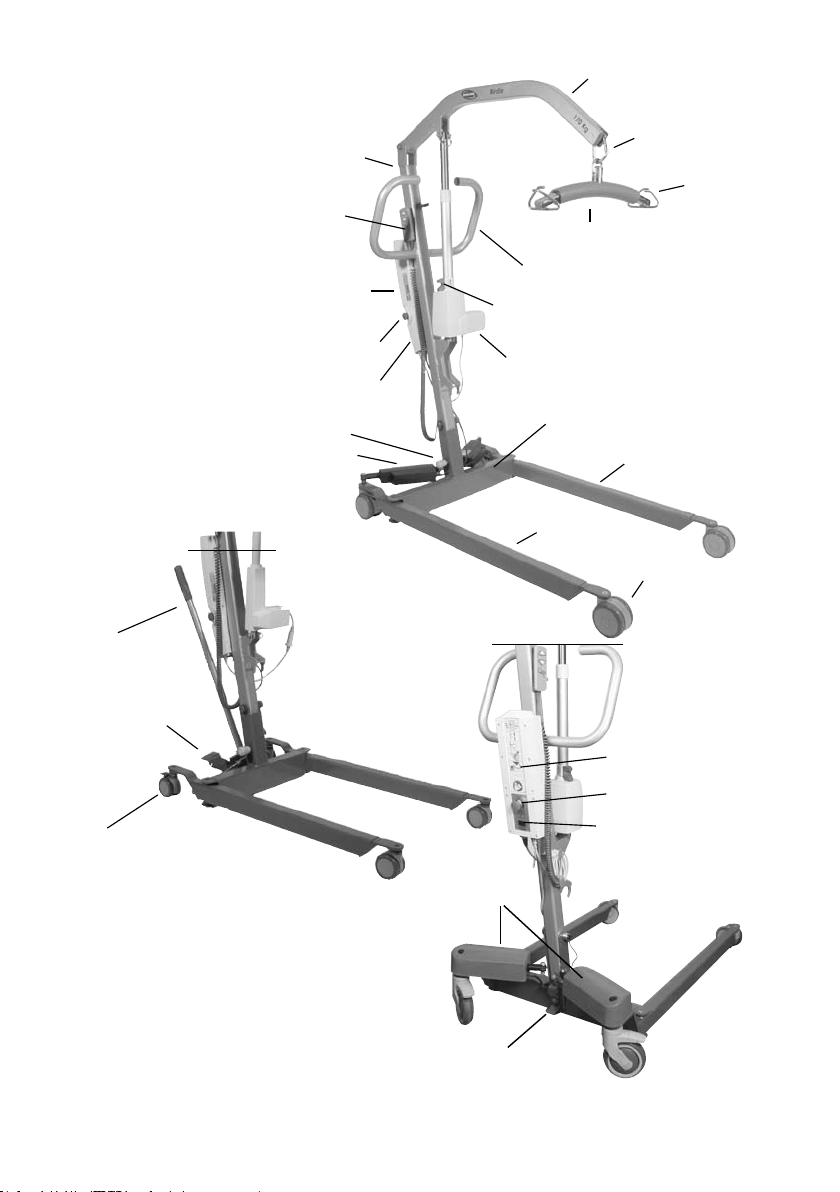
2. Main parts of the hoist
Jib
Leg spreader
handle
(optional)
Foot pedal
Mast
Hand control
Control unit
Emergency stop
Battery
Locking pin
Motor for operation
of electric legs
Carabiner
Spreader bar
Handle bar
Manual emergency
lowering handle
Motor
Base
Left leg
Right leg
Castor
Birdie
Hook for sling
TM
Plus
Castor with brake
Motor for operation
of electric legs
Tilt pedal
Battery
Control unit
Display
9
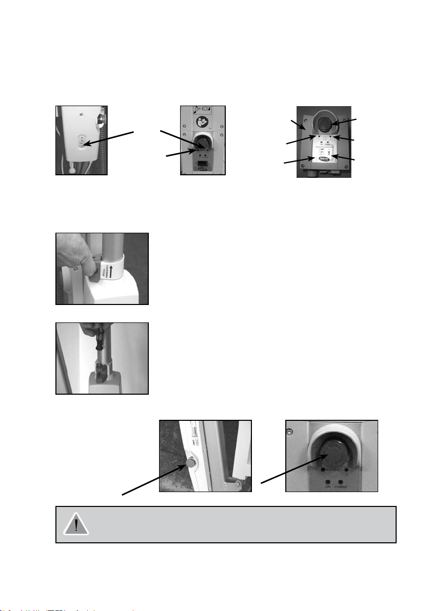
3. Unpacking, assembly and disassembly of the hoist
The packaging is developed for optimal protection of the hoist.•
If you return the hoist• , it must be packed as
delivered in the original box.
You can order replacement boxes from Invacare®. •
Unpacking
Should the packaging be damaged upon receipt, 1.
each part of the hoist must be examined for visible defects.
In the event of any damage, please contact Invacare®.
Carefully take out and identify all the parts in the box.2.
The box contains the following parts:3.
• 1 hoist
• 1 mains cable
• 1 user’s manual
• 1 spreader bar
• 1 manual leg spreader handle (optional)
• 1 sling (optional)
To prevent self-discharging of the battery or accidental operation
of the hoist, the emergency stop is activated during shipping.
Please remember to deactivate the emergency stop and charge
the battery prior to rst use.
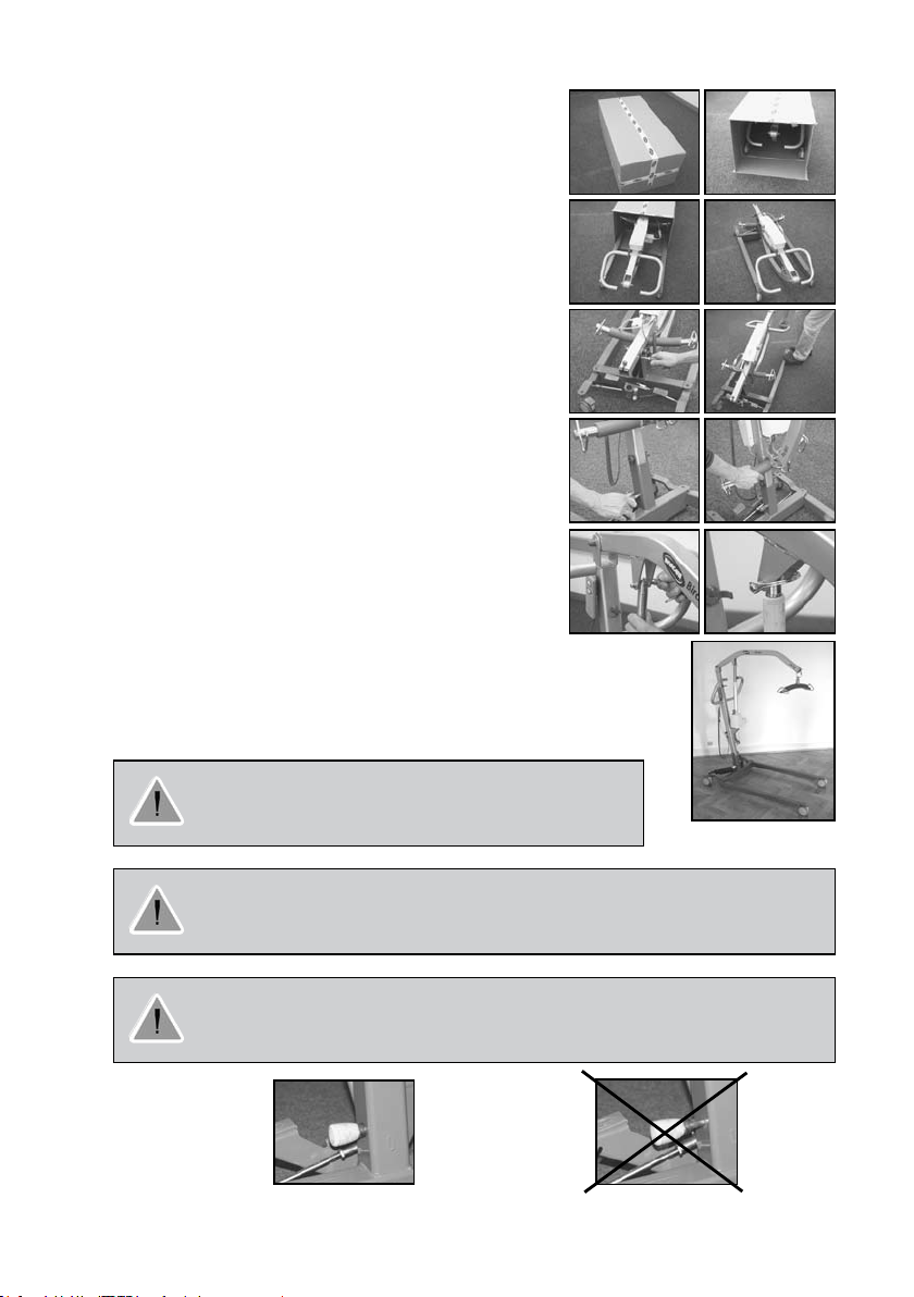
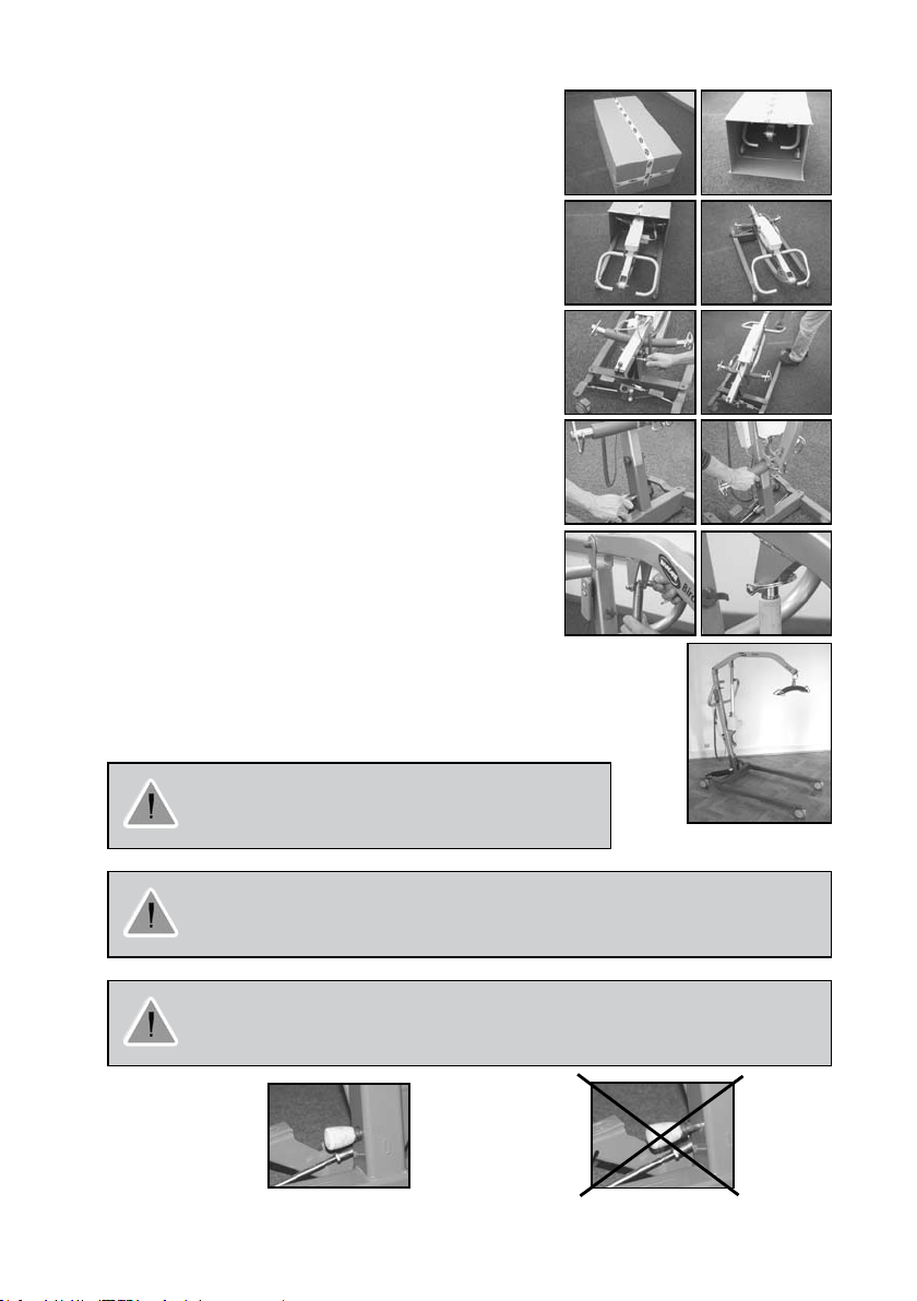
Assembling of the hoist
The hoists are easy to assemble without the use of tools.
Perform unpacking and assembly operation at oor level1.
Take out all the parts of the box (picture 1-4).2.
Apply castor brakes before assembling hoist.3.
Remove the locking pin and raise the mast of the hoist by 4.
pullingthe handle bar (picture 5-6).5.
Insert the locking pin (picture 7 and 12-13 below). Ensure that the locking pin 6.
is correctly inserted as the picture 12.7.
Loosen the spreader bar by pulling it downwards (picture 8).8.
Remove the pipe pin. Assemble the motor and the jib by using the pipe pin 9.
(picture 9-10).
Correctly assembled hoist10. (picture 11).
1
3. 4.
5.
9.
2.
6.
8.
7.
10.
11.
Activate the emergency stop before assembly or disassembly
to prevent entrapment/squeezing.
Remove optional leg spreader handle before disassembly.
There is a possible risk of squeezing of both limbs and wires during assembly and
disassemblyof the hoist. Take the utmost care when lifting components during assembly some parts areheavy. Always remember to adopt the correct lifting position.
Ensure that the locking pin is correctly inserted.
Locking pin correctly
inserted.
12.
Locking pin
13.
incorrectly
inserted.
10
11
Disassembling of the hoist
Lower the jib and narrow both legs completely, and activate the emergency stop button.1.
Apply castor brakes before disassembling hoist.2.
Remove the pipe pin and the motor piston from the jib, reinstall the pipe pin in the piston end, and 3.
lock the motor into the clips on the mast.
Attach the spreader bar into the welded fork on the mast.4.
Remove the locking pin from the base of the mast, release the safety latch, lower the mast, and 5.
relocate the locking pin into the mast near the suspension axle of the mast.
The hoist can now be located in the packaging box, pulled on the rear wheels, or parked in an upright
position with the mast/jib assembly pointing upwards
4. Operating the hoist
Lifting capacity
BirdieTM and Birdie
BirdieTM Compact: 150 kg.
TM
Plus: 170 kg.
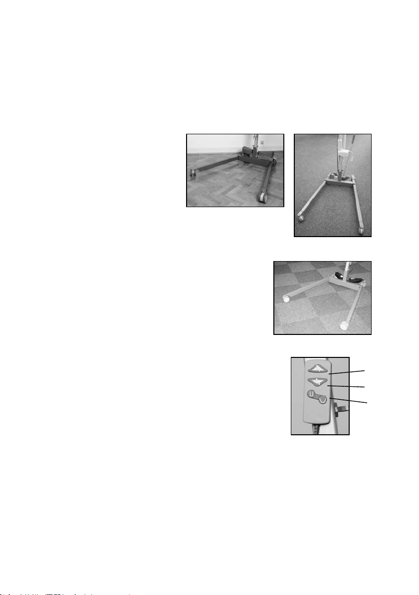
Operation of the manual leg spread
The manual leg span is operated by the 2 pedals on the leg section of the hoist.
The pedals are operated from one side to the other to adjust the distance
between the legs of the hoist.
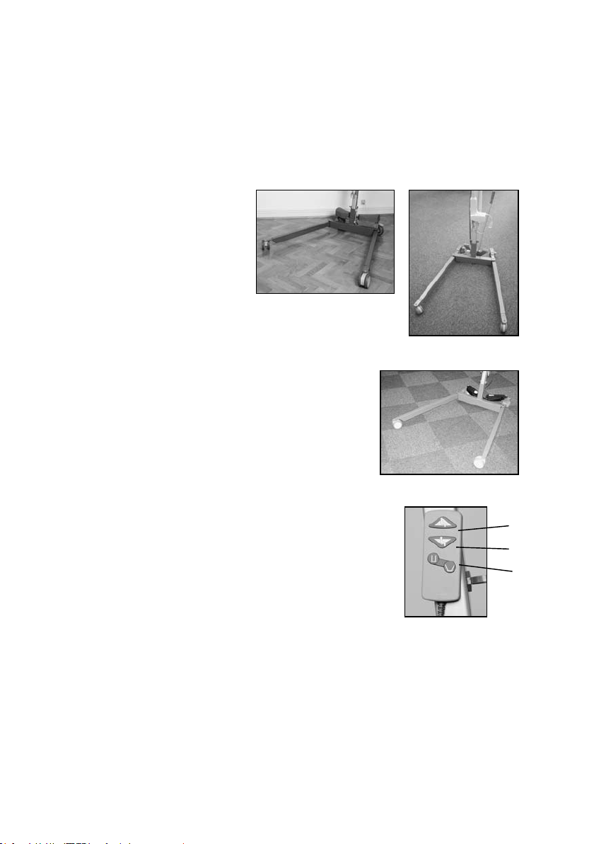
The hand control has 2 buttons – one to raise and one to lower the jib.
Stand behind the hoist and take a rm hold of the handle bar using 1.
both ands.Using your foot, press the left pedal on the base to
increase the distance between the legs.
Using your foot, press the right pedal to decrease the distance 2.
between the legs.
Operation of the electric legs
The distance between the legs is controlled by 2 electric motors
controlled by the hand control.
The hand control has 4 buttons: 2 for raising and lowering the jib and 2 for
operating the electric legs.
Using the hand control
1. Press “arrow up” on the hand control to raise the jib.
2. Press arrow down on the hand control to lower the jib.
3. Operation of electric legs.
Operating forces of buttons: Max. 5 N.
1
2
3
LED diodes on the control unit
BirdieTM and BirdieTM Compact - the upper yellow diode will blink during charging, and switch to
continuous light when fully charged. The lower green diode will light continuously when the control unit
is connected to the mains, and light up when any button on the remote control is pressed, or when the
electric emergency lowering is activated.
BirdieTM Plus - the left green diode will light continuously when the control unit is connected to the mains.
The yellow right diode will light continously during charging, and go out when the battery is fully charged.
There is no indication when hand control buttens are pressed, or when the emergency lowering/raising
system is activated.
11
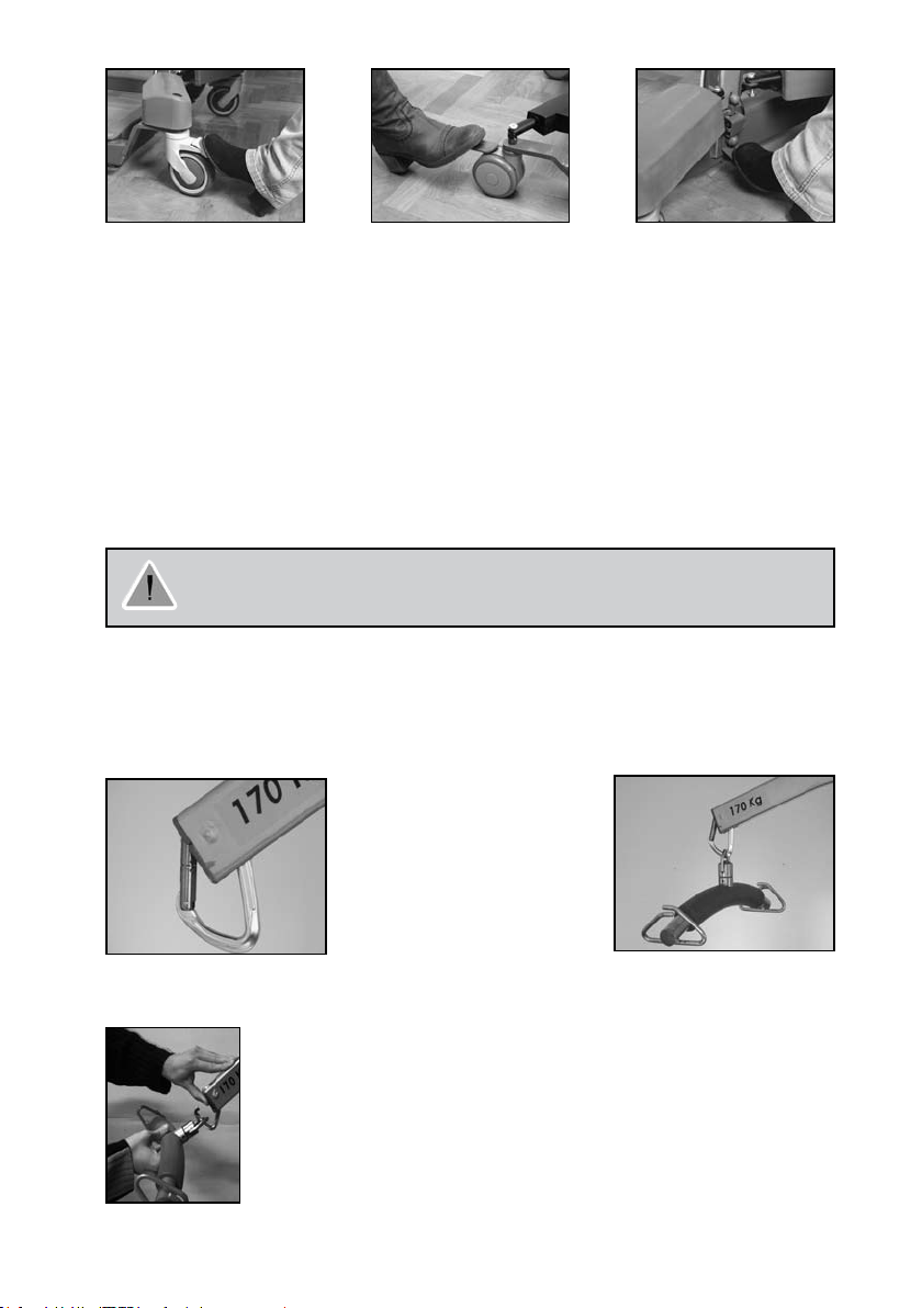
Brakes
Stand behind the hoist and take a good hold of the handle bar.1.
Press the pedals downwards by feet on the back castors to activate the brake.2.
Press the pedals upwards by feet to release the brake.3.
Moving the hoist
Stand behind the hoist and take a good hold of the handle bar.1.
Release the brakes of the back castors.2.
Now the hoist can be pushed or pulled to the desired location.3.
Note: To negotiate raised obstacles during movement of the unloaded hoist, it is recommended to
pull the hoist backwards. This operation should only be performed when the hoist is in the unloaded
condition.
Tilt pedal
The tilt pedal is used for tilting when the hoist must be moved from one room to another, to force a
footstep. Place one foot on the tilt pedal, and pull the empty hoist rearwards to a suitable angle.
WARNING! Never use the tilt pedal with a patient in the hoist.
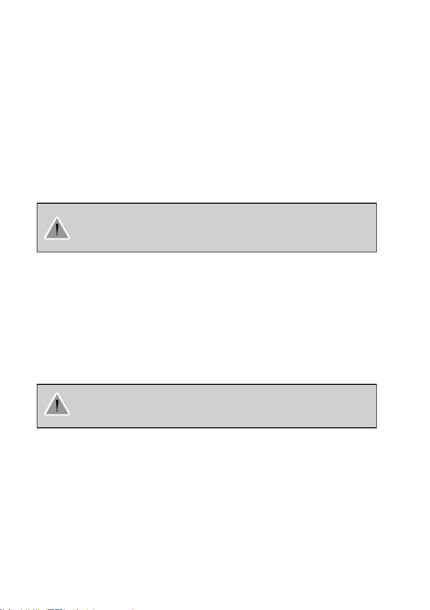
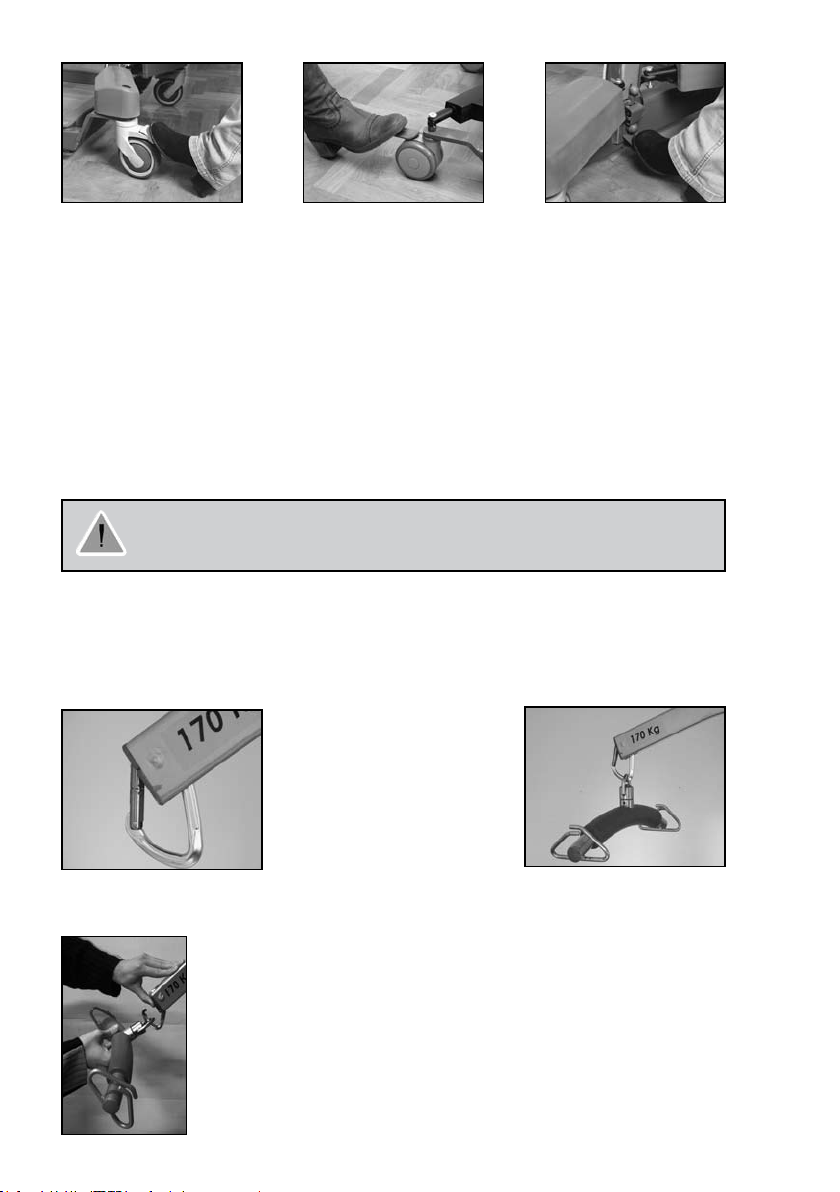
Mounting the spreader bar
The spreader bar is easy mounted and dismounted on the carabineer hook:
Open the carabineer hook with one nger, and mount or dismount the spreader bar.
Use only spreader bars made for the BirdieTM mobile hoists.
Make sure the spreader bar is suitable for the patient and the actual lift or transfer required.
Carabineer correctly positioned on
the lifting arm, ready for use.
Easy opening of the carabineer by pushing the
safety catch backwards with one nger and
attachment of the spreader bar.
Correctly attached spreader
bar.
12
13
Fitting the sling
Slings designed for 2- or 4-point spreader bars can be used with this mobile hoist, please refer to
Invacare®’s sling brochure for details.
Note: The size of the sling and the width of the spreader bar should correspond.
Choose the most appropriate sling for the patient. The carer must be trained in the use of hoists 1.
before performing any transfers.
Carefully inspect the hoist and the sling. If defective parts are found, the damaged parts must be 2.
replaced.
Only use slings suited for the hoist and the patient.3.
Place the patient in the sling as described in the sling manual. Pay special attention to the fact that 4.
the sling is correctly applied.
Lower the jib and mount the straps of the sling. If the patient is in a sitting position, the jib must be 5.
lowered to chest height and the hoist must be moved as close as possible to the patient.
Make sure that there are no obstructions when raising the jib. 6. Ensure that brakes are not engaged
before
lifting or lowering.
Caution! Do not lift or lower a patient with the brakes applied. Always let the hoist find the
correct centre of gravity. Make sure that the lifting area is between the legs of the hoist.
Never operate the hoist when the patient is outside the base and leg area. Always be careful
when lifting or lowering a patient. Never exceed the maximum recommended lifting capacity.
Charging the battery
The hoists are equipped with an internal charger. It is recommended to charge the batteries regularly to
ensure optimal use of the hoist and prolong the life of the batteries. Furthermore, it is recommended to
charge the batteries before rst use.
The control unit is equipped with a sound signal, which will beep when operating with low battery capacity.
It is recommended to charge the batteries as soon as the sound signal is heard. In addition, BirdieTM Plus
is equipped with a display, indicating the approximately remaining battery capacity.
How to charge the batteries:
Connect the mains cable to the control unit and plug it in. It takes about 4 hours to charge 1.
the batteries. Charging must take place in a room with good air ventilation. The charger stops
automatically when the batteries are fully charged.
Remember to disconnect the charger cable before using the hoist again.2.
The emergency stop must not be activated - otherwise it will be impossible to charge
the batteries. While charging takes place the hoist cannot be used. Do not use or move the
hoist without unplugging from the socket outlet. Do not attempt to use the hoist if the battery
housing is damaged. Replace a damaged battery housing before further use.
13
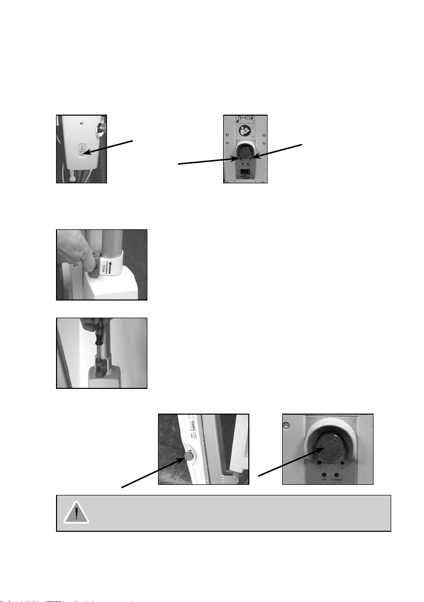
5. Emergency lowering, emergency lifting and emergency stop
Electric emergency lowering BirdieTM, BirdieTM Compact and Birdie
If the hand control fails, the jib can be lowered by using the circular switch for emergency lowering. This
is located at the front of the control unit. The jib will be lowered as long as the button is pressed. On
TM
Birdie
Plus the button should be operated by means of a sharp object, such as a pencil.
Birdie
TM
and Birdie
TM
Compact Birdie
TM
Plus Jumbo Care Control Unit
TM
Plus
Emergency lowering
Emergency
lifting
Electric emergency lifting - Birdie
TM
Control Unit
Emergency lifting
Battery capacity
Plus
Emergency stop
Emergency lowering
Maintenance Indicator
(Refer to page 14)
If the hand control fails, the jib can be raised by using the button for emergency lifting. This is located at
the front of the control unit, and should be operated with a sharp object, such as a pencil. The jib will be
lifted as long as the button is pressed.
Manual emergency lowering - Birdie
TM
and Birdie
TM
Plus
In case of partial or total power failure, or if the battery runs down
while using
the hoist, BirdieTM and BirdieTM Plus is equipped with a manual
emergency lowering system located at the bottom of the motor.
The weight is preset for 75 kg. If the patient’s weight is more or
less than 75 kg, it might be necessary to adjust the manual emergency
lowering.
Adjustment of the manual emergency lowering
- Birdie
TM
and Birdie
TM
Plus
If the lowering speed has to be adjusted according to the patient’s weight,
then the screw in the red release handle must be adjusted. Loosen to
increase the speed and tighten to decrease the speed.
Note: Manual emergency lowering is only possible when a patient is
sitting in the hoist.
Emergency stop
In case of emergency:
Press the red button for
emergency stop.
The emergency stop can be
reset by turning the stop
button
patient in the hoist.The mechanical emergency lowering system has to be adjusted
Note!The mechanical emergency lowering system will only operate when there is a
according to the patient’s weight.

14
15
6. Accessories
It is compulsary to use original Invacare® spare parts which you can buy through any Invacare® dealer.
For repair, please contact your local Invacare®dealer.
Sling : See the sling brochure
7. Maintenance and cleaning
At normal daily operation, a service check-up should take place every year, according to the maintenance chart.
When performing annual or regular maintenance, all parts designed to carry load must be as a minimum tested
with maximum load. All safety features must be checked according to EN ISO 10535: 2006 Annex B.
LOLER statement.
The UK Health and Safety Executive's Lifting Operations and Lifting Equipment Regulations 1998, require any
equipment that is used in the workplace to lift a load be subject to safety inspection on a six monthly basis.
Please refer to the HSE web site for guidance www.hse.gov.uk
Jumbo care functions.
In add for a safe maintenance, the JUMBO Care offers ve (5) main functions:
1) Service intervals
2) Service information on PC
3) Actuator life time
4) Resetting of service interval
5) Actuator exchange
(For more information, see technical Jumbo care user manual or ask your local Invacare dealer)
It is the responsibility of the person responsible for the equipment to ensure that LOLER regulations are adhered
to.
The hoist must be stored at normal room temperature. If it is stored in a damp, cold or wet environment then
the motor and other mounting parts may be prone to corrosion.
The hoist• have been designed so that it requires a minimum amount of maintenance.
It is recommended that the batteries are charged frequently, if possible every night, as it will extend the •
lifetime of the batteries and will ensure high performance.
It is recommended that the hoist• is cleaned after use.
Please check that the spreader bar connections, control unit and motors are in good working order and •
not damaged in any way. If there is any damage to the hoist, refrain from using it, and contact your local
Invacare®dealer before further use.
Wear and damage of loading parts
It is necessary to maintain and check all parts that are exposed to static or dynamic strain, such as the sling, the
spreader bar and the turning points, do not have fractures, are fragile, askew or damaged.
Frequent use of the hoist will cause the carabiner to ware under the contact points of the spreader bar (b) and
the mast pin (a). Do not use the hoist if the thickness of the carabineer measures less than 6 mm at these points.
(See maintenance chart page 15)
Damaged parts must be replaced before further use.
Cleaning
To prevent cross-infection, the hoists must be cleaned after use.•
The hoist must be wiped with a moist rmly wrung cloth with ordinary household disinfectants.•
Only use ofcially approved disinfection detergents.•
Dry the hoist carefully after cleaning.•
Never use acids, alkaline or solvents for cleaning the hoist.•
Motors, control unit and mounting parts can be destroyed if the hoist is cleaned in any other way than stated
above.
15
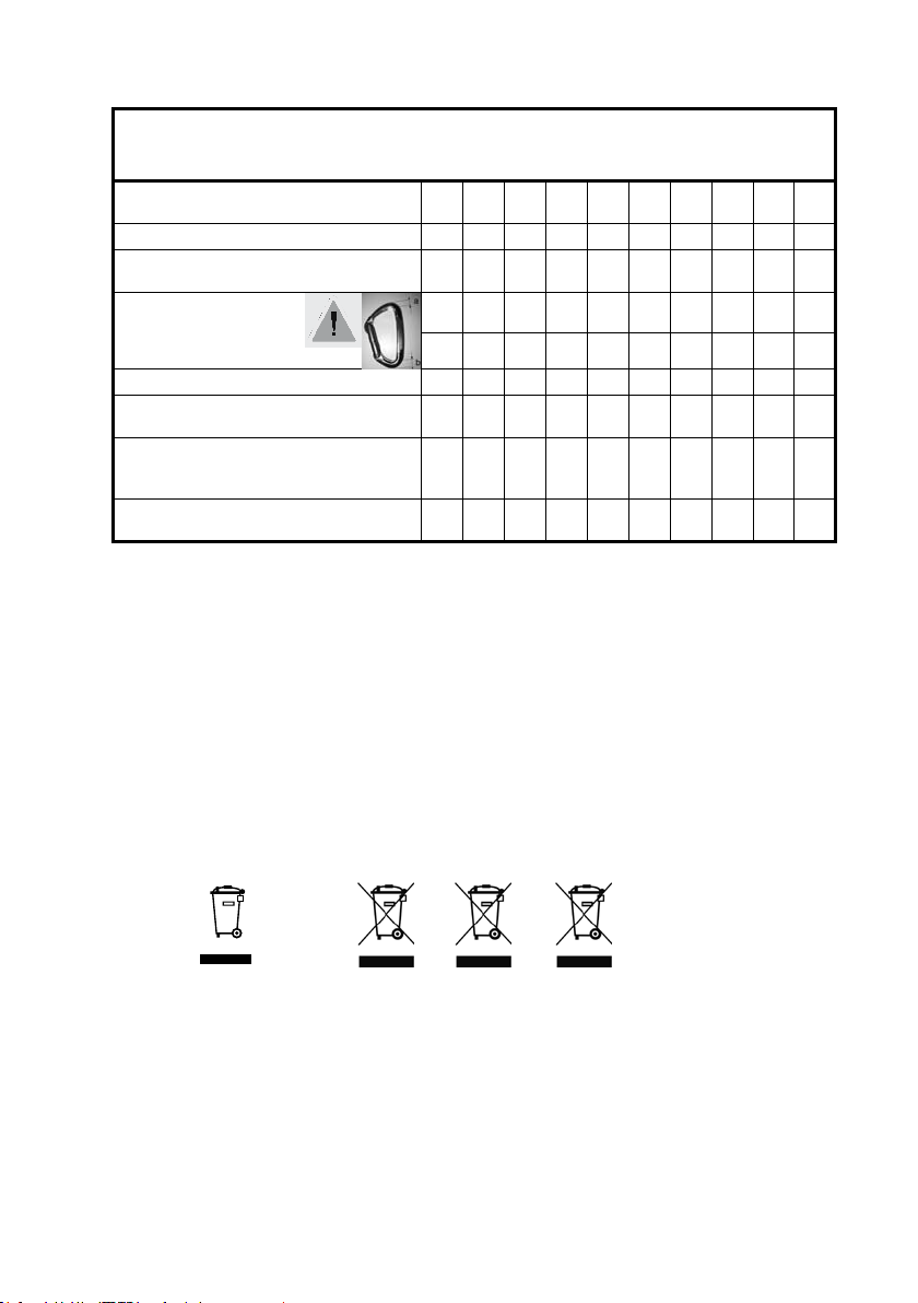
Maintenance chart
Only personnel having received the necessary instruction or training by Invacare® must
perform service and maintenance on BirdieTM, Birdie
TM
Plus and Birdie
TM
Compact.
Serial number (located on the hoist base): _______________________
Date:
/ / / / / / / / / / / / / / / / / / / /
Initials:
Visual inspection of all hoist parts
Inspection of the spreader bar and
carabiner - welding and assemblies
Inspection of carabineer*
(the thickness "a" and "b"
mustn't measure less than 6 mm
"a" = "a" = "a" = "a" = "a" = "a" = "a" = "a" = "a" = "a" =
"b" = "b" = "b" = "b" = "b" = "b" = "b" = "b" = "b" = "b" =
Inspection of the motors - undamaged
Inspection of cables and plugs -
undamaged
Inspection of emergency stop, electrical
emergency lowering and -raising (only
TM
Birdie
Plus)
Inspection of the castors - attachment,
braking ability and free rolling
®
Invacare
offers courses in service and maintenance of the hoist.
For all servicing and maintenance requirements, please contact your local Invacare®dealer.
8. Waste disposal
This product has been supplied from an environmentally aware manufacturer that complies with the
Waste Electrical and Electronic Equipment (WEEE) Directive 2002/96/CE.
This product may contain substances that could be harmful to the environment if disposed of in places
(landlls) that are not appropriate according to legislation.
The ‘crossed out wheelie bin’ symbol is placed on this product to encourage you to recycle wherever
possible.
Please be environmentally responsible and recycle this product through your recycling facility at the end
of it’s life.
Battery:
Pb Hg Cd

16
17
9. Trouble-shooting
Only personnel having received the necessary instruction or training by Invacare® must perform service
and maintenance on Birdie
TM
, Birdie
TM
Plus and Birdie
TM
Compact.
Symptom Possible cause Remedy
The mast seems loose The mast axis screw has
become loose
Insert the locking pin into the
mast axis screw, and tighten the
screw
Castors are noisy Dust or dirt in the castors Clean the castors
Hinge between jib and mast is
Missing lubrication Lubricate the hinge
noisy during operation
The motor is not running Hand control or motor
Insert the plugs fully
is not connected
No power on the battery Charge or replace the battery
Motor noise, but no movement in
The red emergency stop
is activated
Motor is damaged Replace the motor
Turn the red button clockwise to
deactivate
the piston rod
The piston rod only moves
Motor is damaged Replace the motor
in and not out
The control unit emits a beeping
sound during lifting, and the
jib motor stops (BirdieTM and
TM
Birdie
Compact).
The jib motor stops (Birdie
Max. load is exceeded Reduce the load (and the hoist
will function normally)
TM
Plus)
Contact your dealer if the above does not solve your problems.
Lubricate with medically clean oil, e.g. Kemitura Kem Lub KEM-WO 50, order no. 813239.
17
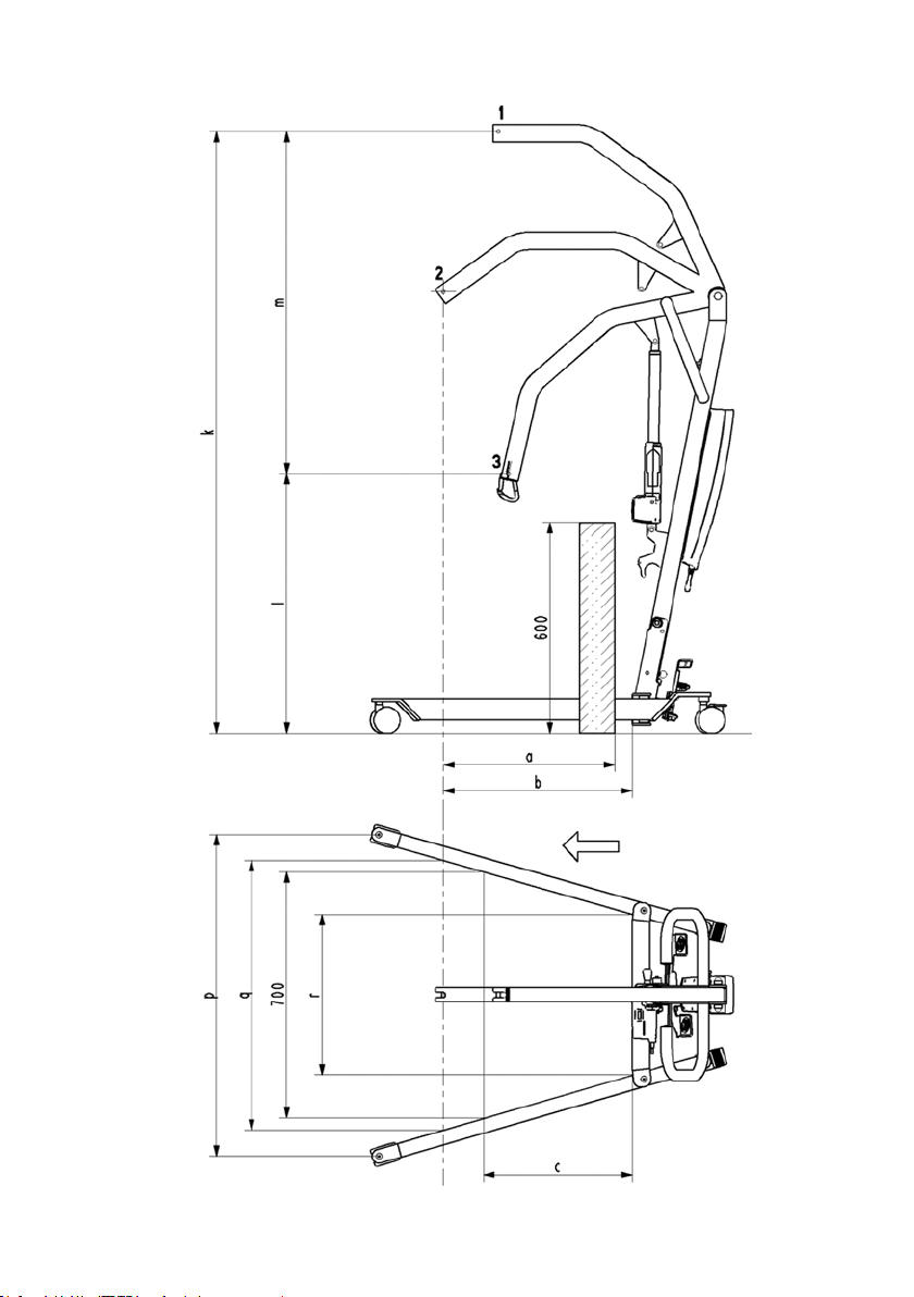
10. Technical specifications
Direction
of travel

18
19
General specifikations Manual and electric
Castor Ø 75 mm Ø 100 mm Ø 100 mm + Ø 125 mm Ø 75 mm Ø 100 mm
Maximum lifting capacity 170 kg 170 kg 150 kg
Lowest position (min.
height of CSP**) 3*
Lifting area
(height range)
Maximum height
of CSP**
Leg length 115 cm 116,5 cm 100 cm
Minimum internal width 58 cm 58 cm 46 cm
Total width (closed),
external measure
Interal width
at maximum reach
Total width (open)
internal measure
Total width (open) centre
to centre of castor
Turning radius 140 cm 140 cm 107 cm
Weight, mast, incl. battery,
excl. spreader bar
Total weight incl.
spreader bar
Weight, leg section * 19 kg 21 kg 16,5 kg
Height to upper edge of legs
Min. free height
Min. space for patient (to
(motor) in top position
Maximum reach at 60 cm
Maximum reach from base
Reach from base with
legs spread to 70 cm
Hoisting range 123,5 cm 123,5 cm 107 cm
Voltage output 24 V max. 250 VA
Voltage supply 100 -240 V 50/60 Hz
Max. current input Max. 200 mA Max. 400 mA Max. 200 mA
Operating temperature. 5o to 40o C
Air humidity 20% to 90% @ 30o C - not condensing
Sound pressure 45-50 dB(A)
Atmospheric pressure 700 to 1060 hPa
Protection class,
control unit
Protection class,
hand control
Protection class, motor IPX4
Insulation class II - type B
Working ability 40 full lifts without battery charge with batteries at 50% of full capacity
Intermittens 10%, max. 2 minuttes/18 minuttes
Battery capacity 2,9 Ah 2,9 Ah + display 2,9 Ah
Manual emergency lowering Ye s Yes No
Electric emergency lowering/
lifting
*
65,5 cm 67 cm 67 cm 73 cm 74,5 cm
l
46,5 - 168,5 cm47,5 - 170
*
k
189 cm 190,5 cm 190,5 cm 180 cm 181,5 cm
*
r
65,5 cm 68 cm 68 cm 53 cm 55 cm
*
q
*
p
10 cm 11,5 cm 11,5 cm 10 cm 11,5 cm
2 cm 3,5 cm 3,5 cm 2 cm 3,5 cm
*
a
*
b
*
c
*
m
TM
Birdie
cm
91 cm 91 cm 78 cm
104 cm 104 cm 89 cm
108,5 cm 108,5 cm 93 cm
21 kg 21,5 kg 17,5 kg
42 kg 44 kg 36 kg
34 cm 34 cm 30 cm
66,5 cm 66,5 cm 54,5 cm
66,5 cm 66,5 cm 54,5 cm
24 cm 24 cm 41,5 cm
Yes/No Yes/Yes Yes/No
BirdieTM Plus
47,5 - 170 cm 51,5 - 158,5 cm53 - 160 cm
IPX4
IPX4
Manual
BirdieTM Compact
19
All measurements are given including a 45 cm 2 point spreader bar, except dimensions marked with *.
Invacare® reserves the right to change the measurements without warning.
** CSP: Central Suspension Point
1: Highest position, 2: Maximum reach position, 3: Lowest position
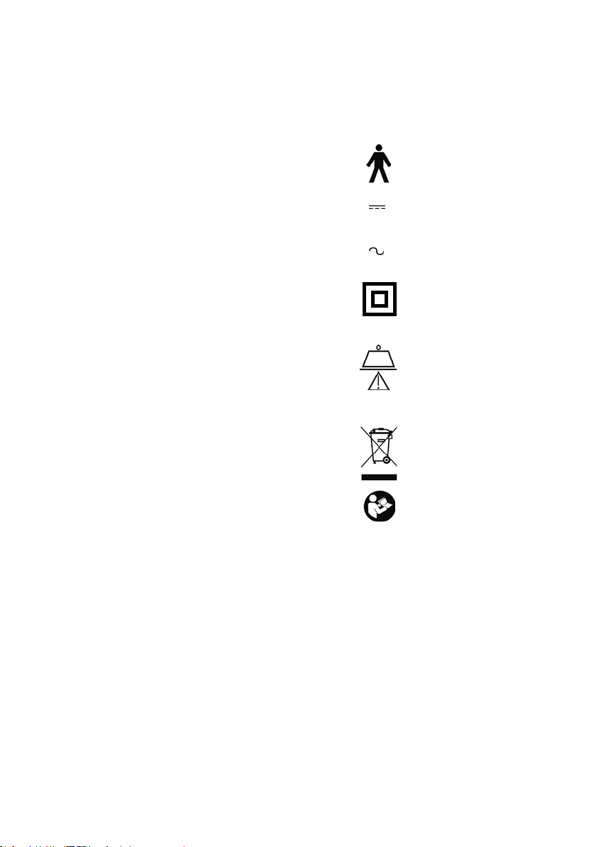
11. Symbols
The patient is not separated from the ground and the chassis:
Direct current:
Alternating current
Double insulated:
X kg max. load (SWL) = (Patient + sling + spreader bar).
X = 150 kg (BirdieTM Compact)
X = 170 kg (Birdie
TM
and Birdie PlusTM)
The product should be reused where possible:
Refer to user’s manual:

20
21
FR
Manuel d’utilisation
Cachet du Distributeur

21
Table des matières
1. Généralités ...........................................22
2. Eléments principaux du lève-personnes ...................24
3. Déballage, assemblage et démontage du lève-personne .....25
4. Fonctionnement du lève-personnes ......................26
5. Bouton de descente d’urgence et bouton d’arrêt d’urgence. . . 29
6. Accessoires ..........................................30
7. Maintenance et Désinfection ............................30
8. Recyclage des déchets .................................31
9. Court-circuit ..........................................32
10. Caractéristiques techniques .............................33
11. Symboles ............................................35

22
23
Félicitations!
Vous avez choisi le lève-personne mobile BirdieTM, BirdieTM Plus et BirdieTM Compact. BirdieTM sont
spécialement conçu pour le transfert du patient de et vers un fauteuil roulant, un lit, des toilettes ou le
sol. BirdieTM permettent une manipulation plus facile et un plus grand confort dans le secteur infirmier.
La nouvelle conception des BirdieTM lui confère une plus longue portée, une plus grande ouverture des
pieds, une plus large gamme de levage.
Le choix d’une ouverture électrique ou manuelle des pieds associé à la large gamme de fléaux et de
sangles disponibles facilitent le réglage du lève-personne pour le confort optimal du patient.
Tout au long du processus entier de production, nos matériaux/produits font l’objet de contrôles qualité
réalisés par les opérateurs. Un essai final est effectué lorsque le produit est totalement assemblé. Si le
produit ne répond pas aux exigences de qualité d’Invacare®, il sera refusé lors du contrôle qualité.
En cas de problème en rapport avec le produit livré, veuillez contacter votre fournisseur local Invacare®.
Invacare® décline toute responsabilité si le produit est utilisé ou assemblé de toute autre façon que
celle indiquée dans le présent guide utilisateur. Seuls les accessoires mentionnés dans le présent guide
utilisateur peuvent être utilisés sur le lève-personne mobile BirdieTM.
Ce produit doit être manipulé uniquement par un personnel qualifié qui a reçu l’instruction et la formation
nécessaires.
Veuillez lire et vous familiariser avec le présent guide utilisateur avant de manipuler le lève-personne
mobile BirdieTM.
1. Généralités
• BirdieTM présentent le marquage conformément à la directive 93/42/CEE concernant les appareils
médicaux.
• BirdieTM ont été testés selon EN ISO 10535.
• Le boîtier de commande et les moteurs ont été homologués EN 60601.
• BirdieTM ont fait l’objet d’une analyse des risques selon EN ISO 14971.
• Le boîtier de commande, la commande manuelle et les moteurs sont protégés à la classe IP X4.
• Capacité de levage : BirdieTM et BirdieTM Plus 170 kg, Birdie CompactTM 150 kg.
• Le lève-personnes a une durée de vie approximative de 8 ans.
Débrancher la prise de l’alimentation secteur avant de déplacer ou d’utiliser le lève-personne.
S’assurer que le câble secteur n’est pas comprimé ni endommagé d’aucune façon lorsque le lèvepersonne est déplacé.
Si les fonctions du lève-personne changent, consultez la section du présent guide utilisateur concernant
les réparation et la maintenance.
Ce produit doit être réparé et entretenu par un personnel qualifié.
23
Veuillez considérer attentivement les risques suivants lors de l’utilisation du BirdieTM :
Le lève-personne doit être contrôlé avec précaution si le patient si le patient est un enfant.
Veuillez noter qu’il est plus difficile de manœuvrer le lève-personne sur de la moquette ou
sur des surfaces inégales/texturées contrairement au parquet ou à des surfaces planes. Ceci
est dû aux forces nécessaires pour amorcer le mouvement qui peuvent créer des points de
frottement supplémentaires sur les roues.
Il est recommandé de ne pas élever le patient à la hauteur maximum de la flèche.
Soyez très vigilant lorsque le lève-personne est déplacé vers une zone humide, glissante ou
sur sol inégal.
Attention ! Lorsqu’un patient est levé, il doit toujours être placé entre les pieds du lèvepersonne. Ne jamais essayer de manipuler le lève-personne si le patient est en dehors du
pied de base. Soyez toujours vigilant lors du levage ou de l’abaissement d’un patient.
Invacare® décline toute responsabilité pour tout usage, changement ou assemblage du
lève-personne BirdieTM différent de ceux indiqués dans le présent guide utilisateur.
Il existe un risque de pincement pour l’aidant pendant le transfert et le déplacement du lèvepersonne.
Ne jamais dépasser la capacité de levage maximale recommandée.
S’assurer que le câble secteur n’est pas comprimé ni endommagé d’aucune façon lorsque le
lève-personne est déplacé.
Important ! Invacare® recommande que l’utilisation de tout lève-personne mobile soit
effectuée par le personnel ayant reçu des instructions ou suivi une formation sur les
transferts et les techniquesde manipulations.
Toujours choisir le type de sangle adapté au poids, à la taille et aux capacités physiques du
patient. Toujours s’assurer que la sangle est fixée correctement. Ne jamais laisser un patient
seul dans une sangle.
Veuillez vous assurer que le lève-personne ne soit pas humide afin qu’il ne soit pas
endommagé.
La goupille de vérrouillage doit être actionnée pendant le transport du lève-personnes.
La chute du lève-personnes durant le transport pourrait entrainer des dommages.
24
25
2. Eléments principaux du lève-personnes
Mât
Commande
manuelle
Flèche
Mousqueton
Crochet de fixation
de la sangle
Fléau
Levier d’écartement manuel du
piétement
Pédale pour
le pied
Roulette avec frein
Batterie
Arrêt d’urgence
Boîtier de
commande
Goupille de
verrouillage
Moteur pour écartement
électrique du piétement
Poignée
Poignée de descente
d’urgence manuelle
Moteur
Base
Pied gauche
Pied droit
Roulette
Batterie
Unité centrale
Afchage
Moteur pour pieds
electriques
TM
Birdie
Plus
Pédale de
bascule
25
3. Déballage, assemblage et démontage du lève-personne
• L’emballage est conçu pour une protection optimale du lève-
personne.
• Si vous retournez le Birdie
originale intacte.
• Vous pouvez commander des boîtes supplémentaires auprès
d’Invacare®.
Déballage
1. Si l’emballage s’avère être endommagé à la réception, chaque pièce
du lève-personne doit être examinée afin de détecter les éventuels
défauts apparents.En cas de dommage, veuillez contacter Invacare®.
2. Retirer avec précaution toutes les pièces de la boîte et les
examiner.
3. La boîte contient les pièces suivantes :
• 1 lève-personne
• 1 câble de raccordement au secteur
• 1 guide utilisateur
• 1 fléau
• 1 manuel d’ouverture manuelle des
pieds (en option)
• 1 sangle (en option)
Pour prévenir les risques de décharge complète de la batterie ou les
mouvements accidentels du lève-personnes, le bouton d’arrêt
d’urgence est actionné lors de l’expédition du produit. Désactiver le
bouton rouge d’arret durgnce et faire une première charge avant la
première utilisation.
TM
, il doit être emballé dans la boîte
Assemblage du lève-personne
Les lève-personnes le BirdieTM d’Invacare®sont faciles à
assembler sans utiliser d’outils.
1. Retirer toutes les pièces de la boîte (photos 1 à 4)
2. Enlever la goupille de verrouillage et relever le mât du lève-personne en tirant la
poignée (photos 5 et 6)
3. Insérer la goupille de verrouillage (photos 7 et 12-13 ci-dessous)
4. Débloquer le fléau en le tirant vers le bas (photo 8)
5. Enlever la goupille. Assembler le moteur et la flèche en utilisant la goupille
(photos 9 et 10)
6. BirdieTM sont correctement assemblé (photo 11)
Activer l’arrêt d’urgence avant l’assemblage ou le
désassemblage pour éviter les pincements.
Enlever l’ouverture manuelle despieds en option
avant l’assemblage.
1
3. 4.
5.
7.
9.
2.
6.
8.
10.
11.
Il existe un risque de pincement des membres et des câbles pendant l’assemblage et le
désassemblage du lève-personne
Prendre le plus grand soin quand vous levez les composant durant l’assemblage – certaines
parties sont lourdes. Toujours se souvenir d’adopter la position correcte de levée.
Assurez vous que la goupille de verrouillage est correctement insérée.
Goupille de vérouillage
correctement insérée
12.
Goupille de vérouillage
incorrectement insérée
13.
26
27
Démontage du lève-personne
1. Rabaisser la flèche et rabattre les 2 pieds complètement, et activer le bouton d’arrêt d’urgence.
2. Enlever la goupille et le piston du moteur de la flèche , réinstaller la goupille dans le piston, et
verrouiller le moteur dans les clips du mât.
3. Attacher le fléau dans la branche soudée.
4. Enlever la goupille de verrouillage , relâcher le loquet de sécurité, descendre la mât, et replacer la
goupille de verrouillage dans le mât près de l’essieu de suspension sur le mât.
Le lève-personne doit être placée dans le carton d’emballage., tiré sur les roues arrières ou rangé dans
une position droite avec le mât/flèche pointant vers le haut.
4. Fonctionnement
du Birdie
Capacité de levage
TM
Birdie
Birdie CompactTM: 150 kg
Ouverture manuelle des pieds
L’ouverture manuelle des pieds est actionnée par les 2 pédales situées sur les
pieds du lève-personne. Les pédales sont actionnées depuis un côté vers un
autre afin d’ajuster la distance entre les pieds du lève-personne.
1. Se placer derrière le lève-personne et tenir fermement la poignée.
2. Appuyer sur la pédale gauche située sur la base en aluminium afin
d’augmenter la distance entre les pieds.
3. Appuyer sur la pédale droite afin de réduire la distance entre
les pieds.
Caractéristiques du piétement électrique
La télécommande actionne en simultanée 2 moteurs qui permettent
d’écarter électriquement le piètement.
La télécommande a 4 boutons. 2 permettent la montée et la descente
de la èche, les 2 autres contrôlent l’écartement électrique du piétement.
Levage/abaissement du Birdie
1. Appuyer sur « flèche vers le haut » située sur la commande manuelle afin
de lever la flèche.
2. Appuyer sur « flèche vers le bas » située sur la commande manuelle afin
d’abaisser la flèche
Force requise pour la pression sur les boutons Max.5 N.
TM
et BirdieTM Plus:170 kg
TM
1
2
3
Indicateur visuel pour unité centrale
BirdieTM et Birdie CompactTM - La diode jaune en haut clignote pendant le chargement et switch à une
lumière continue lorsque la batterie est complétement chargée.
La diode verte s’allume en continu lorsque l’unité centrale est connectée sur le secteur et s’étaint lorsqu
un seul bouton est utilisé sur la télécommande ou une fonction electrique d’urgence est activée.
BirdieTM Plus - La diode verte à gauche s’allume en continu lorsque la batterie est connectée sur le
secteur. La diode jaune à droite s’allume en continu pendant la charge et s’éteint en n de charge. Il n’y
a pas d’indication lors de l’utilisation des boutons de controle manuels et lors des descentes et montées
d’urgence.
27
Freins
1. Se placer derrière le lève-personne et tenir fermement la poignée.
2. Appuyer sur les pédales situées sur roulettes arrière afin d’activer les freins.
3. Appuyer de nouveau sur les pédales pour débloquer les freins.
Déplacement du lève-personne
1. Se placer derrière le lève-personne et tenir fermement la poignée.
2. Débloquer les freins des roulettes arrière.
3. A présent, le lève-personne peut être poussé ou déplacé vers l’endroit souhaité.
Remarque: Pour appréhender les obstacles à la levée pendant le mouvement du lève-personne vide, il
est recommandé de tirer le lève-personne par l’arrière.
Pédale de bascule
La pédale de bascule est utilisée lorsque le lève-personne est transféré d’une pièce à l’autre pour passer
un passage de porte avec obstacle. Placer un pied sur la pédale et tirer le lève-personnes vers vous pour
le basculer et passer l’obstacle.
Attention! Ne jamais utiliser la pedale de bascule lors du transfert du patient.
Montage du fléau
Le fléau est facilement montable et démontable sur le mousqueton :
Ouvrir le crochet du mousqueton avec un doigt, et monter ou démonter le fléau.
Utiliser uniquement des fléaux faits pour les lève-personnes mobiles BirdieTM.
S’assurer que le fléau est approprié au patient et à la levée actuelle ou au transfert requit.
Positionner correctement le mousqueton sur la
flèche, prêt pour utilisation.
Facilité d’ouverture du mousqueton en
poussant le loquet de sécurité avec
un doigt. Attacher le fléau dans le
mousqueton.
Voici le fléau correctement attaché.

28
29
Fixation de la sangle
Les sangles conçues pour des fléaux à 2 ou 4 points peuvent être utilisées avec ce lève-personne
mobile, veuillez vous reporter la brochure relative à la sangle d’Invacare® pour de plus amples détails.
Nous recommandons l’utilisation des sangles Invacare avec les lève-personnes Invacare.
Remarque : la taille de la sangle et la largeur du fléau doivent correspondre.
1. Choisir la sangle la mieux adaptée au patient. L’aidant doit avoir suivi une formation sur l’utilisation de
lève-personnes avant d’entreprendre des transferts.
2. Contrôler le lève-personne et la sangle. En cas de défauts, les pièces endommagées doivent être
remplacées.
3. N’utiliser que des sangles adaptées au lève-personne et au patient.
4. Placer la sangle autour du patient comme décrit dans le manuel d’utilisation de la sangle. Veiller
attentivement à ce que la sangle soit correctement montée.
5. Abaisser la flèche, fixer les bandes de la sangle aux crochets de fixation du fléau et serrer les bandes
de la sangle. Si le patient est en position assise, la flèche doit être abaissée à la hauteur de la poitrine et
le lève-personne doit être déplacé plus près du patient/de l’utilisateur.
6. S’assurer qu’il n’existe aucune obstruction lors du levage de la flèche. S’assurer que les freins ne
sont pas enclenchés avant la levée ou la descente du patient.
Attention! Ne pas lever ou baisser le patient avec les freins serrés. Toujours laisser le lèvepersonnes trouver son centre de gravité. S’assurer que la zone de transfert est située entre
les jambes du lève-personnes. NE JAMAIS utiliser le lève-personnes lorsque le patient est
installé en dehors de la base. Toujours faire attention pendant la montée et la descente d’un
patient. NE jamis dépasser la capacité maximale du lève-personnes.
Charge de la batterie
Les lève-personnes sont équipés d’un chargeur intégré. Il est recommande de charger les batteries
régulièrement afin d’assurer une utilisation optimale dulève-personnes et d’assurer la longévité des
batteries. De plus, il est recommandé de charger la batterie avant la première utilisation.
l’unité de contrôle est équipée d’un signal sonore, qui bipera quand la capacité de la batterie sera faible.
Il est recommandé de recharger les batteries si l’alarme se déclenche.
De plus, BirdieTM Plus est équipé d’un indicateur du niveau de la batterie à diode pour faciliter l’utilisation.
Comment recharger les batteries:
1. Connecter le chageur à l’unité de contrôle et brancher. La recharge des batteries dure environ 4
heures.
La charge doit être effectuée dans une pièce aérée. Le chargeur s’arrête automatiquement dès que
la batterie est chargée entièrement.
2. Se rappeler de déconnecter le chargeur avant d’utiliser le lève-personnes à nouveau.
Le lève-personnes ne peut pas être utilisé pendant la durée de chargement des batteries.
Ne pas tenter d’utiliser le lève-personnes lorsque la batteries est endommagée.
Remplacer le bloc batterie avant l’ usage.
29
5. Bouton de descente d’urgence et bouton d’arrêt d’urgence.
Descente électrique d’urgence, BirdieTM, BirdieTM Compact et BirdieTM Plus
Si la télécommande est en panne, la flèche peut être descendue en activant à l’aide d’une pointe le
bouton de descente d’urgence identifié par la mention « Emergency ». Il est localisé en façade de la
batterie. La flèche descendra tant que le bouton de descente d’urgence sera enfoncé à l’aide d’une
pointe.
Birdie
TM
et Birdie
TM
Compact
Descente d’urgence
Montée
d’urgence
Descente
d’urgence
Montée d’urgence, BirdieTM Plus
Si la télécommande tombe en panne, le bras du lève-personnes peut être lever avec le bouoton de
montée d’urgence. Il est situé sur l’avant de l’unité centrale et peut être actionné avec un objet pointu
type stylo. Le bras du lève-personne se lèvera tant que le bouton sera appuyé.
Descente manuelle d’urgence – BirdieTM et BirdieTM Plus
En cas de panne de courant partielle ou totale, ou si la batterie est faible
pendant l’utilisation du Lève-personnes, Birdie est équipé d’une descente
manuelle (de couleur rouge) de la flèche située au niveau du vérin.
Le poids est déterminé à 75 kg. Si le patient a un poids supérieur
ou inférieur à 75 kg , il convient alors de régler la descente manuelle
d’urgence.
Réglage de la descente manuelle d’urgence – Birdie
TM
et
BirdieTM Plus
Si la vitesse de descente d’urgence doit être ajustée en fonction du poids du
patient, alors il faut régler la vis de serrage de la poignée de descente
d’urgence. Desserrer pour augmenter la vitesse, serrer pour ralentir la
vitesse de descente.
Note: La descente manuelle d’urgence est possible seulement quand le
patient est installé dans le lève-personnes.
Arrêt d’urgence
En cas d’urgence: Appuyer sur
le bouton rouge d’arrêt
d’urgence.
L’arrêt d’urgence peut être
enlevé en tournant le bouton
rouge.
Note ! Le système mécanique de descente d’urgence ne pourra fonctionner que lorsque le
patient est installé dans le lève-personnes.
Le système mécanique de descente d’urgence doit être ajusté en fonction du poids du
patient.

30
31
6. Accessoires
Vous devez utiliser des pièces détachées Invacare® disponi¬bles chez tous les Distributeurs Invacare®.
Pour toutes réparations, veuillez vous adresser à votre distributeur qui se chargera de retourner votre
fauteuil au service Après Vente Invacare®.
Sangle : Voir la brochure des sangles
7. Maintenance et Désinfection
Une vérification est nécessaire régulièrement en accord avec le protocole de maintenance.
Lors de la visite de maintenance préventive, Toutes les parties supportant le patient doivent être testés à
la charge maximum supporté par le produit Toutes ces parties doivent être contrôlés dans le respect de la
norme EN ISO 10535:2006 Annex B.
Le lève-personne doit être stocké dans une pièce à température ambiante. Si le produit est stocké dans
une pièce froide ou humide, le moteur ainsi que les parties mécaniques de l’appareil risquent d’être
endommagées par la corrosion.
• La conception des BirdieTM requiert un minimum de maintenance.
• Il est recommandé de charger les batteries régulièrement, toutes les nuits si possible, afin d’assurer
la longévité des batteries et une performance haute et constante.
• Il est recommandé de nettoyer le BirdieTM après chaque utilisation.
• Vérifier que l’accroche du fléau, l’unité de contrôle et les moteurs fonctionnent correctement et que
chaque élément ne soit pas endommagé. Tout endommagement détecté sur le lève-personnes qui
empêcherait le bon focntionnement de l’appareil doit être signalé à Invacare® avant l’usage.
Entretien des éléments
Il est nécessaire d’entretenir et de vérifier tous les éléments qui sont exposés à une tension à la fois
statique et dynamique (par exemple la sangle, le fléau ou le mousqueton); ils ne doivent pas être fissurés,
déchirés, endommagés.
L’utilisation fréquente du lève personne entraînera une usure du mousqueton entre les points d’attaches
au fléau (A) et à la flèche (b). Ne pas utiliser le lève personne si l’épaisseur du mousqueton est inférieure
à 6 mm à ces points d’attaches (se reporter aux conditions de maintenance page 31)
Les éléments endommagés doivent être remplacés avant l’usage.
Desinfectiond
• Pour prévenir des infections, Les lève-personnes BirdieTM doivent être désinfectés après chaque
utilisation.
• Le lève-personnes doit être nettoyé avec un linge propre et sec et un désinfectant classique.
• Utilisation d’un désinfectant officiellement reconnu et approuvé.
• Sécher attentivement le lève-personnes aprèx le nettoyage.
• Ne jamais utiliser d’acides, alkalines ou solvents pour nettoyer le lève-personnes.
Moteurs, unité de contrôle et autres éléments peuvent être détruites si les BirdieTM ont été néttoyés selon
les précautions d’usage indiquées ci-dessus.
 Loading...