

Invacare Arrow RWD, Torque? SP RWD, Ranger X? RWD, 3G Storm Arrow RWD, 3G Storm Torque SP RWD Service Manual
...
Service Manual
3G Storm Series® Wheelchairs
Arrow® RWD
Torque SP RWD
Ranger X RWD
DEALER: KEEP THIS MANUAL. THE PROCEDURES
IN THIS MANUAL MUST BE PERFORMED BY AN
AUTHORIZED DEALER ONLY

W
A
R
N
I
N
G
WARNING
WARNING
THE PROCEDURES IN THIS MANUAL SHOULD ONLY BE PERFORMED BY
A QUALIFIED SERVICE TECHNICIAN.
DO NOT SERVICE OR OPERATE THIS EQUIPMENT WITHOUT FIRST
READING AND UNDERSTANDING THIS MANUAL AND THE OWNER’S
MANUAL SUPPLIED WITH THE WHEELCHAIR. IF YOU ARE UNABLE TO
UNDERSTAND THE WARNINGS, CAUTIONS, AND INSTRUCTIONS,
CONTACT INVACARE TECHNICAL SUPPORT BEFORE ATTEMPTING TO
SERVICE OR OPERATE THIS EQUIPMENT - OTHERWISE INJURY OR
DAMAGE MAY RESULT.
SPECIAL NOTES
S
P
E
C
A
L
N
O
T
E
S
WARNING/CAUTION notices as used in this manual apply to hazards or unsafe practices
which could result in personal injury or property damage.
NOTICE
I
THE INFORMATION CONTAINED IN THIS DOCUMENT IS SUBJECT TO CHANGE WITHOUT
NOTICE.
WHEELCHAIR USER
As a manufacturer of wheelchairs, Invacare endeavors to supply a wide variety of
wheelchairs to meet many needs of the end user. However, final selection of the type
of wheelchair to be used by an individual rests solely with the user and his/her healthcare
professional capable of making such a selection.
WHEELCHAIR TIE-DOWN RESTRAINTS AND SEAT POSITIONING STRAPS
Invacare recommends that wheelchair users NOT be transported in vehicles of any
kind while in wheelchairs. As of this date, the Department of Transportation has not
approved any tie-down systems for transportation of a user while in a wheelchair, in a
moving vehicle of any type.
It is Invacare’s position that users of wheelchairs should be transferred into appropriate seating in vehicles for transportation and use be made of the restraints made
available by the auto industry. Invacare cannot and does not recommend any wheelchair transportation systems.
AS REGARDS RESTRAINTS - SEAT POSITIONING STRAPS - IT IS THE OBLIGATION OF THE DME
DEALER, THERAPISTS AND OTHER HEALTHCARE PROFESSIONALS TO DETERMINE IF A SEATING
POSITIONING STRAP IS REQUIRED TO ENSURE THE SAFE OPERATION OF THIS EQUIPMENT BY
THE USER. SERIOUS INJURY CAN OCCUR IN THE EVENT OF A FALL FROM A WHEELCHAIR.
SAVE THESE INSTRUCTIONS
2

TABLE OF CONTENTS
TABLE OF CONTENTS
NOTE: The information in this owner's manual applies to the STORM ARROW , STORM TORQUE X, RANGER
X, and the RECLINER Wheelchairs except where specified.
SPECIAL NOTES ................................................................................................................................... 2
SPECIFICATIONS
FOR ARROW.................................................................................................................................... 5
FOR TORQUE SP ........................................................................................................................... 6
FOR RANGER X .............................................................................................................................. 7
PROCEDURE 1 - GENERAL GUIDELINES ...........................................................................................8
REP AIR OR SERVICE INFORMA TION ..............................................................................................8
OPERA TING INFORMATION .............................................................................................................8
WARNING/CAUTION LABEL LOCA TION....................................................................................... 10
PROCEDURE 2 - TROUBLESHOOTING ............................................................................................ 12
FIELD LOAD TEST .........................................................................................................................1 2
USING HYDROMETER TO CHECK BA TTER Y CELLS (LEAD ACID).............................................. 12
MOTOR TESTING........................................................................................................................... 13
MOTOR BRUSH INSPECTION ....................................................................................................... 14
ELECTRO-MECHANICAL P ARKING BRAKE TESTING................................................................... 14
PROCEDURE 3 - HARDWARE TORQUE SPECIFICATIONS .............................................................. 15
ST ANDARD SEAT FRAME.............................................................................................................. 15
CAPT AINS VAN SEA T...................................................................................................................... 16
ADJUST ABLE SEA T FRAME ...........................................................................................................16
BASE FRAME HARDWARE T ORQUE SPECIFICA TIONS .............................................................. 17
T
A
B
L
E
O
F
C
O
N
T
E
N
T
S
PROCEDURE 4 - ARMS ....................................................................................................................... 18
REPLACING ARMREST P ADS - CAPT AINS VAN SEA T .................................................................. 18
REPLACING CAPT AINS V AN SEAT ARMREST PLA TE ................................................................... 18
PROCEDURE 5 - UPHOLSTERY/POSITIONING STRAP .................................................................. 19
REPLACING SEA T POSITIONING STRAP - CAPT AINS VAN SEA TS............................................... 19
REPLACING BACK UPHOLSTERY ................................................................................................ 19
PROCEDURE 6 - SEAT FRAME........................................................................................................... 21
PREP ARATIONS FOR REMOVING/INST ALLING SEA T FRAME (ST ANDARD FRAME,
ADJUST ABLE FRAME AND CAPTAINS V AN SEA T.......................................................................... 21
REPLACING EXACT SAME SIZE ST ANDARD SEA T FRAME .......................................................... 2 2
REMOVING/INST ALLING STANDARD SEA T FRAME SUB-ASSEMBL Y ........................................... 22
CHANGING SEA T DEPTH ............................................................................................................... 23
CHANGING SEA T WIDTH (STANDARD AND ADJUST ABLE SEA T FRAME) ................................... 25
INST ALLING/REMOVING ADJUSTABLE SEA T FRAME SUBASSEMBL Y AND/OR
COMPONENT REPLACEMENT................................................................................................. 26
INST ALLING/REMOVING CAPT AINS VAN SEA T ASSEMBL Y........................................................ 28
REPLACING CAPT AINS V AN SEA T AND/OR CAPT AINS V AN SEA T FRAME .............................. 28
CONVERTING FROM ST ANDARD SEAT FRAME TO ADJUST ABLE SEA T FRAME
OR VICE VERSA....................................................................................................................... 29
CONVERTING FROM ADJUST ABLE SEA T FRAME TO CAPT AINS V AN SEA T
OR VICE VERSA....................................................................................................................... 29
CONVERTING FROM ST ANDARD SEA T FRAME TO CAPT AINS V AN SEA T
OR VICE VERSA....................................................................................................................... 30
REMOVING/INST ALLING SEA T P AN.............................................................................................. 30
MOUNTING PLA TE - SEA T ANGLE ADJUSTMENT AND INST ALLA TION ORIENTA TION ............ 31
PROCEDURE 7 - BASE FRAME .......................................................................................................... 32
REPLACING SEA T MOUNTING PLATES......................................................................................... 32
REPLACING SEA T SUPPOR T BRACKETS.................................................................................... 32
REPLACING SEA T SUPPOR T BRACKET T-NUTS ........................................................................33
REPLACING BA TTERY CHARGER BRACKET AND T-NUT............................................................ 34
REMOVING/INST ALLING SEAT STOP SCREWS............................................................................ 34
PROCEDURE 8 - BACK FRAME.......................................................................................................... 35
REPLACING CJ BACK BRACKETS................................................................................................ 35
CHANGING BACK HEIGHT ............................................................................................................. 36
BACK ANGLE ADJUSTMENT.......................................................................................................... 38
3

TABLE OF CONTENTS
TABLE OF CONTENTS (Continued)
PROCEDURE 9 - BATTERIES ............................................................................................................. 39
T
A
B
L
E
O
F
C
O
N
T
E
N
T
S
INST ALLING/REMOVING BATTERIES INT O/FROM BATTERY BOX(ES)......................................... 39
DISCONNECTING/CONNETING BA TTERY CABLES...................................................................... 40
WHEN TO CHARGE BATTERIES ................................................................................................... 44
CHARGING BA TTERIES ................................................................................................................. 44
REPLACING BA TTERIES................................................................................................................ 46
REMOVING/INST ALLING GROUP 24 BATTER Y BOXES FOR WHEELCHAIRS NOT
EQUIPPED WITH VENT TRA Y ..................................................................................................... 47
REMOVING/INST ALLING GROUP 24 BATTER Y BOXES FOR WHEELCHAIRS NOT
EQUIPPED WITH VENT TRA Y ..................................................................................................... 48
INST ALLING/REMOVING BATTER Y BOX - 22NF BATTER Y BASE FRAME ..................................... 49
PROCEDURE 10 - WIRING HARNESS .................................................................................................. 50
REMOVIN G/INSTALLING THE WIRING HARNESS............................................................................ 50
ADJUSTING LIMIT SWITCH............................................................................................................. 54
PROCEDURE 11 - RETENTION STRAP/RETAINER......................................................................... 55
REPLACING BA TTERY BOX RET AINER/RET AINER CLIP - GROUP 24 BA TTERY BASE FRAMES.. 55
PROCEDURE 12 - WHEELS/MOTORS ............................................................................................. 57
REPLACING PNEUMA TIC TIRES/TUBES - DRIVE WHEELS/CASTERS ........................................... 57
REMOVING/INST ALLING DRIVE WHEELS......................................................................................... 57
REMOVING/INST ALLING DRIVE WHEEL HUB ................................................................................... 58
INST ALLING WHEEL LOCK BRACKET ONTO WHEEL CHAIR ......................................................... 58
REMOVING/INST ALLING CASTERS .................................................................................................. 59
REPLACING FORKS ......................................................................................................................... 59
REMOVING/INST ALLING THE MOTOR (CONVENTIONAL MOTOR WITH GEARBOX) ...................... 60
REMOVING/INST ALLING THE MOTOR (GEARLESS BRUSHLESS MOTOR).................................... 61
PROCEDURE 13 - ELECTRONICS .................................................................................................... 66
REPOSITIONING MKIV JOYSTICK - V AN SEAT MODELS.................................................................. 63
REMOVING/INST ALLING MKIV CONTROLLER .................................................................................. 64
PROCEDURE 14 - RECLINER ........................................................................................................... 68
POSITIONING LIMIT SWITCH ............................................................................................................ 68
ADJUSTING LIMIT SWITCH................................................................................................................ 68
REPLACING RECLINER CABLE ASSEMBLIES ................................................................................. 69
REPLACING/ADJUSTING GAS CYLINDERS ...................................................................................... 70
CHANGING BACK HEIGHT ................................................................................................................ 71
CHANGING SEA T DEPTH .................................................................................................................. 72
CHANGING SEA T WIDTH .................................................................................................................. 72
EQUIPMENT OPTION INST ALLING/REPLACING ADJUSTABLE 16 TO 19-INCH DEEP
RECLINER SEA T FRAME ONT O ARROW OR X BASE FRAME.................................................... 73
PROCEDURE 16 - RWD WHEELCHAIRS ............................................................................................. 74
REMOVING/INST ALLING GROUP 24 BATTERY BOX SUB-FRAME........................................................ 7 4
REMOVING/INST ALLING 22NF BATTERY BOX TRA Y ............................................................................ 7 6
EQUIPMENT OPTION CONVERTING 22NF BATTERY BOX TRAY TO GROUP 24 BA TTERY
BOX SUB FRAME ......................................................................................................................... 76
SHOCK OR RUBBER ELEMENT REPLACEMENT FOR WHEELCHAIRS
EQUIPPED WITH GROUP 24 BA TTERIES....................................................................................... 79
SHOCK OR RUBBER ELEMENT REPLACEMENT FOR WHEELCHAIRS
EQUIPPED WITH 22NF BA TTERIES .............................................................................................. 81
SHOCK SPRING REPLACEMENT ....................................................................................................... 8 2
REMOVING/INSTALLING GEARBOX .................................................................................................... 83
ADJUSTING WEIGHT DISTRIBUTION .................................................................................................. 84
REPOSITIONING MOTOR/GEARBOX ................................................................................................. 8 5
REPOSITIONING THE GEARLESS/BRUSHLESS MOTOR ................................................................... 8 6
REPLACING SUSPENSION ARM FOR WHEELCHAIRS WITH MOTOR/GEARBOX ASSEMBL Y............. 87
REPLACING THE SUSPENSION ARM FOR WHEELCHAIRS WITH GEARLESS/BRUSHLESS MOTOR. 88
ANTI-TIPPER WHEEL REPLACEMENT ............................................................................................... 8 9
REMOVING INST ALLING THE ANTI-TIP ASSEMBLY .............................................................................. 89
LIMITED WARRANTY........................................................................................................................... 91
4

SPECIFICATIONS FOR ARROW
S
P
E
C
I
F
I
C
A
T
I
O
N
S
Seat Width Range:
Standard 12 to 24-inches
Recliner 14 to 24-inches
Seat Depth Range:
Standard 12 to 22-inches
Recliner 14 to 22-inches
Back Height Range:
Standard 12 to 24-inches
Recliner 18-1/2 to 26-inches
Back Angle Range:
Standard 80
Recliner 90o to 170
Seat-to-Floor (approximate)
Standard: 17-1/2 -inches
Optional: 19-3/4-inches
Overall Width of Base:
(w/o joystick) 25-inches
o
to 1 15
21-inches
SPECIFICATIONS
Drive Axle: ◆ Adjustable
u
Non-Recliners ONLY.
Drive Wheels/Tires:
(Foam Filled or Pneumatic)
Standard: 14 X 3-inches
Optional: 14 X 4-inches
S
P
E
C
I
F
I
C
PHYSICAL DIMENSIONS
Casters w/Precision
Sealed Bearings
o
o
Semi-Pneumatic
Standard: 8 X 2-1/4-inches
Option: 6 X 2-inches (w/ shock fork)
Pneumatic or Foam Filled
Standard: 8 X 2-inches
Option: 9 X 2-3/4-inches
Anti-Tippers (3-inch wheels): Standard
Caster Forks: Standard, Shock Fork (Optional)
A
T
I
O
N
S
Overall Height
Standard: 34-1/4-inches
Minimum: 34-1/4-inches
Maximum: 44-1/4-inches
Recliner
Low Seat Frame: 51-1/2-inches
Med. Seat Frame: 53-3/4-inches
High Seat Frame: 55-1/2 inches
Overall Length
(without front riggings)
Standard: 29-1/2-inches
Long Frame: 32-1/2-inches
Weight
Gearless/Brushless Motor
W/O GP24 Batteries: 174 lbs.
With GP24Batteries: 278 lbs.
Shipping (approx.): 214 lbs.
Footrests: T elescoping Front Rigging Supports, Swing-
Away (Std), Heavy Duty (Opt.), 2-in. and 4-in. longer Pivot
Slide Tube (Opt)
Armrests: Flip Back, Fixed or Adjustable Height (Desk
and Full Length)
Seat Angle Adjustment: Adjustable (0
Back Angle Adjustment: Adjustable (80
increments)
Seat Cushion: Cushion (Optional)
Chair Upholstery Options: Naugahyde and Nylon
Battery requirements: See chart on page 46
Weight Limitations: Arrow with gearless/brushless
motor - up to 300 lbs. Arrow with 4 pole motor - up to
400 lbs.
o
to 10o)
o
to 1 15o in 5
PERFORMANCE
RA TING SPEED RANGE
G/B motor 4 Pole Motor
300 lbs up to 8 mph N/A up to 29
o
4 Pole Motor
Without Batteries: 162 lbs.
With Batteries: 266 lbs.
Shipping (approx.): 202 lbs.
400 lbs N/A up to 4.5 mph up to 19
Range will vary with battery conditions, surface, terrain and operators weight.
5

SPECIFICATIONS - TORQUE SP
SPECIFICATIONS - TORQUE SP
S
P
E
C
I
F
I
C
A
T
I
O
N
S
Seat Width Range:
Standard 12 to 22-inches
Recliner 14 to 22-inches
Seat Depth Range:
Standard 12 to 22-inches
Recliner 16 to 22-inches
Back Height Range:
Standard 12 to 24-inches
Recliner 18-1/2 to 26-inches
Back Angle Range:
Standard 80
Recliner 90o to 170
Seat-to-Floor (approximate)
Standard: 17-1/2-inches
Optional: 19-3/4-inches
Overall Width of Base:
(w/o joystick) 25-inches
Overall Height
Standard: 34-1/4-inches
Minimum: 34-1/4-inches
Maximum: 44-1/4-inches
Recliner
Low Seat Frame: 51-1/2-inches
Med. Seat Frame: 53-3/4-inches
High Seat Frame: 55-1/2 inches
Overall Length
(without front riggings)
Standard: 29-1/2-inches
Long Frame: 32-1/2-inches
Drive Axle: ◆ Adjustable
o
to 1 15
21-inches
Drive Wheels/Tires:
(Foam Filled or Pneumatic)
Standard: 14 X 3-inches
Optional: 14 X 4-inches
PHYSICAL DIMENSIONS
Casters w/Precision
Sealed Bearings
Semi-Pneumatic
Standard: 8 X 1-1/4-in
Option: 6 X 2-in.(w/ shock fork)
o
o
Pneumatic or Foam Filled
Standard: 8 X 2-inches
Option: 9 X 2-3/4-inches
Anti-Tippers (3-inch wheels): Standard
Caster Forks: Standard, Shock Fork (Optional)
Footrests: Telescoping Front Rigg Supports, Swing-
Away , Heavy Duty , 4-in. longer Pivot Slide Tube (Opt)
Armrests: Flip Back, Fixed or Adjustable Height (Desk
and Full Length)
Seat Angle Adjustment: Adjustable (0
Back Angle Adjustment: Adjustable (80
o
to 10o)
o
to 1 15o in 5
o
increments)
Seat Cushion: Cushion (Optional)
Chair Upholstery Options: Naugahyde and Nylon
PERFORMANCE
RA TING SPEED RANGE
G/B motor 4 Pole Motor
250 lbs N/A up to 4.5 mph up to 19
251-300 lbs up to 8 mph up to 29
up to 4.5 mph up to 19
301-350 lbs N/A up to 4.5 mph up to 19
Range will vary with battery conditions, surface, terrain and operators weight.
u
Non-Recliners ONLY.
BATTERY REQUIREMENTS , WEIGHT LIMITATIONS, CHAIR WEIGHT
MODEL MOTOR LIMITATION BATTERIES W/O BATT. W/ BATT. WEIGHT
U250TQ 4 Pole Motor Up to 250 lbs *22NF 154 228 194 lbs
251-300TQ 4 Pole Motor 251-300 lbs *22 NF 154 22 8 194 lbs
251-300TQ Gearless/Brushless 251-300 lbs Group 24 16 6 27 0 206 lbs
301-350TQ 4 Pole Motor 301-350 lbs Group 24 154 2 58 194 lbs
* Two batteries inside one battery box.
WEIGHT CHAIR WEIGHT SHIPPING
6

SPECIFICATIONS - TORQUE SP
SPECIFICATIONS - RANGER X
Seat Width Range:
Standard 12 to 22-inches
Recliner 14 to 22-inches
Seat Depth Range:
Standard 12 to 22-inches
Recliner 14 to 22-inches
Back Height Range:
Standard 12 to 24-inches
Recliner 18-1/2 to 26-inches
Back Angle Range:
Standard 80
Recliner 90o to 170
Seat-to-Floor (approximate)
Standard: 17-1/2-inches
Optional: 19-3/4-inches
Overall Width of Base:
(w/o joystick) 25-inches
Overall Height
o
to 1 15
21-inches
o
o
Drive Axle: ◆ Adjustable
u
Non-Recliners ONLY.
Drive Wheels/Tires:
(Foam Filled or Pneumatic)
Standard: 14 X 3-inches
Optional: 14 X 4-inches
PHYSICAL DIMENSIONS
Casters w/Precision
Sealed Bearings
Semi-Pneumatic
Standard: 8 X 2-1/4-in
Option: 6 X 2-in. (w/ shock fork)
Pneumatic or Foam Filled
Standard: 8 X 2-inches
Option: 9 X 2-3/4-inches
Anti-Tippers (3-inch wheels): Standard
Caster Forks: Standard, Shock Fork (Optional)
Footrests: T elescoping Front Rigging Supports, Swing-
Away (Std), Heavy Duty (Opt.), 4-in. longer Pivot Slide
Tube (Opt)
S
P
E
C
I
F
I
C
A
T
I
O
N
S
Standard: 34-1/4-inches
Minimum: 34-1/4-inches
Maximum: 44-1/4-inches
Recliner
Low Seat Frame: 51-1/2-inches
Med. Seat Frame: 53-3/4-inches
High Seat Frame: 55-1/2 inches
Overall Length
(without front riggings)
Standard: 29-1/2-inches
Long Frame: 32-1/2 -in ches
Weight
Gearless/Brushless Motor
Without GP 24 Batteries: 174 lbs.
With GP 24 Batteries: 278 lbs.
Shipping (approx.): 214 lbs.
4 Pole Motor
Without GP 24 Batteries: 162 lbs.
With GP 24 Batteries: 266 lbs.
Armrests: Flip Back, Fixed or Adjustable Height (Desk
and Full Length)
Seat Angle Adjustment: Adjustable (0
Back Angle Adjustment: Adjustable (80
o
to 10o)
o
to 100o in 5
o
increments)
Seat Cushion: Cushion (Optional)
Chair Upholstery Options: Naugahyde and Nylon
Battery requirements: Group 24
Weight Limitations: 300 lbs.
PERFORMANCE
RA TING SPEED RANGE
G/B motor 4 Pole Motor
300 lbs up to 6.5 mph up to 19
up to 8.0 mph up to 29
Range will vary with battery conditions, surface, terrain and operators weight.
Shipping (approx.): 202 lbs.
7

This Procedure Includes the Following:
Repair or Service Information
G
Operating Information
E
N
Safety/Handling of Wheelchairs
E
R
A
L
G
U
I
D
E
L
I
N
E
S
REPAIR OR SERVICE INFORMATION
Set-up of the Electronic Control Unit is to be performed ONLY by individuals certified by
Invacare. The final tuning adjustments of the controller may affect other activities of
the wheelchair. Damage to the equipment could occur under these circumstances. If
non-certified individuals perform any work on these units, the warranty is void.
OPERATING INFORMATION
Performance adjustments should only be made by professionals of the healthcare field
or persons fully conversant with this process and the driver's capabilities. Incorrect
settings could cause injury to the driver, bystanders, damage to the chair and to surrounding property.
After the wheelchair has been set-up, check to make sure that the wheelchair performs to the specifications entered during the set-up procedure. If the wheelchair
does NOT perform to specifications, turn the wheelchair OFF immediately and reenter
set-up specifications. Repeat this procedure until the wheelchair performs to specifications.
GENERAL GUIDELINESPROCEDURE 1
GENERAL WARNINGS
DO NOT operate on roads, streets or highways.
DO NOT climb, go up or down ramps or traverse slopes greater than 9
o
.
DO NOT attempt to move up or down an incline with a water, ice or oil film.
DO NOT attempt to drive over curbs or obstacles. Doing so may cause your wheelchair
to turn over and cause bodily harm or damage to the chair.
DO NOT use parts, accessories, or adapters other than those authorized by Invacare.
DO NOT leave the power button ON when entering or exiting your wheelchair.
DO NOT stand on the frame of the wheelchair.
DO NOT use the footplates as a platform. When getting in or out of the wheelchair,
make sure that the footplates are in the upward position or swing footrests towards the
outside of the chair.
ALWAYS wear your seat positioning strap.
TIRE PRESSURE
DO NOT use your wheelchair unless it has the proper tire pressure (P.S.I.). DO NOT
overinflate the tires. Failure to follow these suggestions may cause the tire to explode
and cause bodily harm. The recommended tire pressure is listed on the side wall of the
tire.
8

GENERAL GUIDELINES PROCEDURE 1
GENERAL WARNINGS (CONTINUED)
ELECTRICAL
Grounding Instructions:
DO NOT, under any circumstances, cut or remove the round grounding prong from any
plug used with or for Invacare products. Some devices are equipped with three-prong
(grounding) plugs for protection against possible shock hazards. Where a two-prong
wall receptacle is encountered, it is the personal responsibility and obligation of the
customer to contact a qualified electrician and have the two-prong receptacle replaced with a properly grounded three-prong wall receptacle in accordance with the
National Electrical Code. If you must use an extension cord, use ONLY a three-wire
extension cord having the same or higher electrical rating as the device being connected. In addition, Invacare has placed RED/ORANGE WARNING TAGS on some
equipment. DO NOT remove these tags.
BATTERIES
The warranty and performance specifications contained in this manual are based on
the use of deep cycle gel cell or sealed lead acid batteries. Invacare strongly
recommends their use as the power source for this unit.
G
E
N
E
R
A
L
G
U
I
D
E
L
I
N
E
S
Carefully read battery/battery charger information prior to installing, servicing or
operating your wheelchair.
RAIN TEST
INVACARE has tested it’s power wheelchairs in accordance with ISO 7176 Part 9
“Rain Test”. This provides the end user or his/her attendant sufficient time to remove
his/her power wheelchair from a rain storm and retain wheelchair operation.
DO NOT leave power wheelchair in a rain storm of any kind.
DO NOT use power wheelchair in a shower or leave it in a damp bathroom while
taking a shower.
DO NOT leave power wheelchair in a damp area for any length of time.
Direct exposure to rain or dampness will cause the chair to malfunction electrically
and mechanically; may cause the chair to prematurely rust.
Check to ensure that the battery covers are secured in place, joystick boot is NOT
torn or cracked where water can enter and that all electrical connections are
secure at all times.
DO NOT use the joystick if the boot is torn or cracked. If the joystick boot becomes
torn or cracked, replace IMMEDIATELY.
WEIGHT TRAINING
Invacare DOES NOT recommend the use of its wheelchairs as a weight training
apparatus. Invacare wheelchairs have NOT been designed or tested as a seat
for any kind of weight training. If occupant uses said wheelchair as a weight
training apparatus, INVACARE SHALL NOT BE LIABLE FOR BODILY INJURY AND THE
WARRANTY IS VOID.
9
GENERAL GUIDELINESPROCEDURE 1
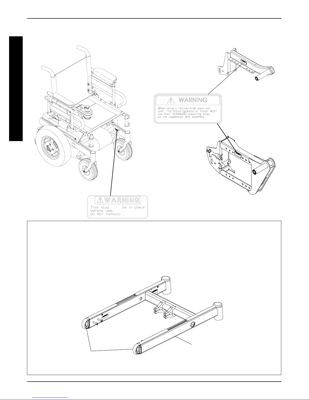
WARNING/CAUTION LABEL LOCATION
G
E
N
E
R
A
L
G
U
I
D
E
L
I
N
E
S
SUSPENSION ARM
USED
WITH CONVENTIONAL
MOTOR/GEARBOX
ASSEMBLY
SUSPENSION ARM USED
NOTE: WARNING LABEL also
found on side frame near the rear
of the chair.
MUST
1070497
WITH GEARLESS/
BRUSHLESS MOTOR
SHIPPING TIE DOWN RESTRAINTS
Invacare recommends that wheelchair users NOT be transported in vehicles of any
kind while in wheelchairs. As of this date, the Department of Transportation has not
approved any tie-down systems for transportation of a user while in a wheelchair,
in a moving vehicle of any type.
Frame end cap can only be used as a shipping tie-down point for an UNOCCUPIED
wheelchair.
FRONT OF
WHEELCHAIR
WHEELCHAIR
Frame End
Caps
REAR OF
Base Frame
10
GENERAL GUIDELINES PROCEDURE 1
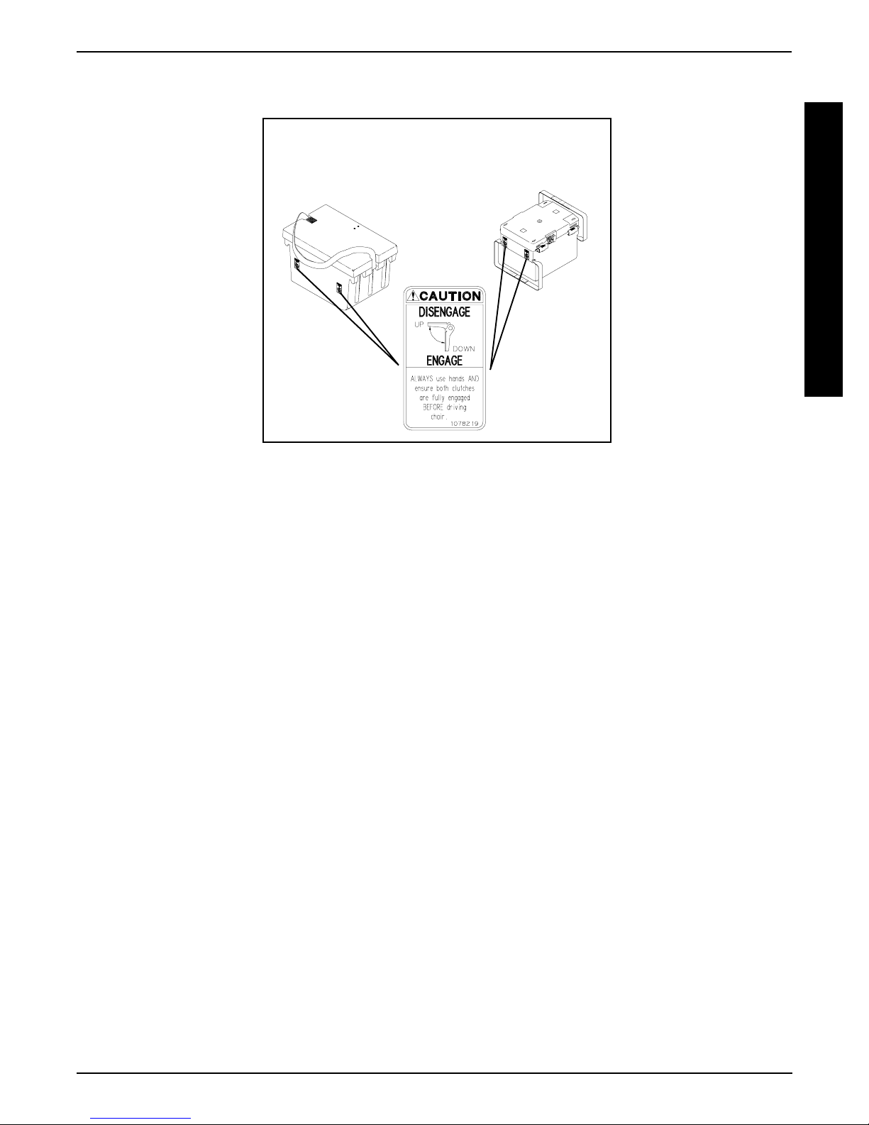
WARNING/CAUTION LABEL LOCATION
NOTE: These caution labels are only found on battery boxes used with the gearless/brushless motor
GROUP 24 BATTERIES
22NF BATTERIES
G
E
N
E
R
A
L
G
U
I
D
E
L
I
N
E
S
11
PROCEDURE 2
TROUBLESHOOTING
This Procedure Includes the Following:
Field Load Test
T
Using Hydrometer To Check Battery Cells (Lead
R
O
O
O
G
Acid)
U
Motor Testing
B
Motor Brush Inspection
L
E
Electro-Mechanical Parking Brake Testing
S
H
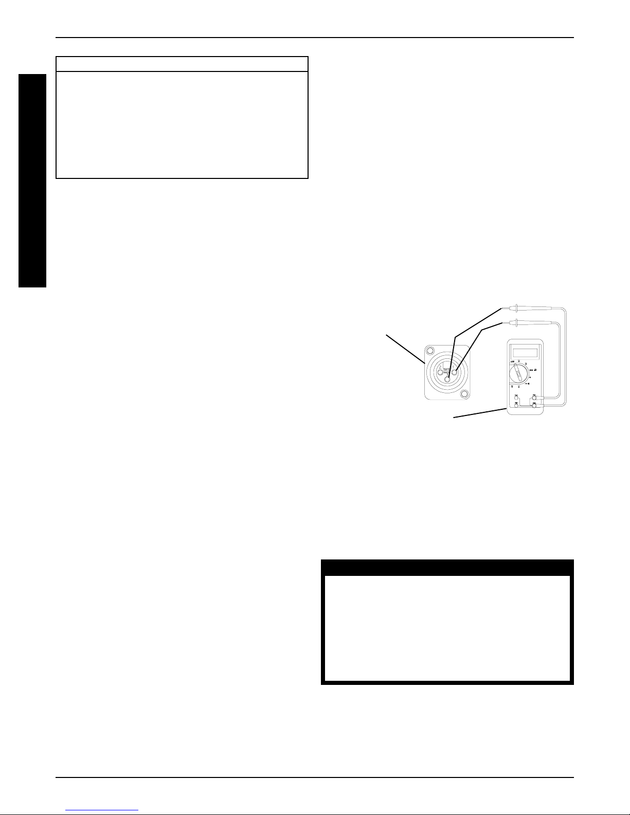
FIELD LOAD TEST (FIGURE 1)
NOTE: The following test can also be performed through
T
the controller of the wheelchair along with a remote pro-
I
grammer. Refer to the individual CONTROLLER
N
MANUAL supplied with each wheelchair.
Old batteries lose their ability to store and release power, due
to increased internal resistance. This means that as you try
to take power from the battery , some of that power is used up
in the process of passing through the battery , resulting in less
voltage at the posts. The more power drawn, the lower the
voltage available. When this lost voltage drops the output 1.0
volts under load (2.0 for a pair), replace the batteries.
4. Place the voltmeter leads into the charger plug on the
wheelchair. Most digital voltmeters are not af fected by
polarity , however, analog meters (meters with swinging needles) can be and should be used carefully . A
good meter reading should be 25.5 to 26 VDC.
5. Have two (2) individuals (one [1] on each arm) apply
as much downward pressure as possible on the arms
of the wheelchair.
6. Turn the wheelchair ON and push the joystick forward, trying to drive the wheelchair through the stationary object. This puts a heavy load on the batteries
as they try to push through the stationary object. Read
the meter while the motors are straining to determine
the voltage under load.
NOTE: If the voltage drops to less than 23.5 volts from a
pair of fully charged batteries while under load, they should
be replaced regardless of the unloaded voltages.
Battery Charger
(-)
Connector
(+)
Testing under load is the only way to spot this problem.
While special battery load testing equipment is available,
it is costly and difficult to transport.
Use a digital voltmeter to check battery charge level at the charger
connector. It is located on the base of the wheelchair frame.
NOTE: READ the instructions CAREFULLY before using the digital voltmeter.
NOTE: Invacare recommends that ONLY qualified ser-
vice personnel perform this test.
1. Ensure that power is OFF.
2. Make sure battery is fully charged. An extremely discharged battery will exhibit the same symptoms as a
bad one.
3. Remove the footrests from the wheelchair and place
the CASTERS of the wheelchair against a wall,
workbench or other stationary object.
Digital Voltmeter
FIGURE 1 - FIELD LOAD TEST
USING HYDROMETER TO CHECK
BATTERY CELLS (LEAD ACID)
(FIGURE 2)
NOTE: Perform this procedure when a digital voltmeter is
not available.
WARNING
NEVER smoke or strike a match near the
batteries. If the caps of the battery cells
are removed, NEVER look directly into
them when charging the battery.
The use of rubber gloves and chemical
goggles or face shields is recommended
when working with batteries.
12

TROUBLESHOOTING
WARNING
PROCEDURE 2
When reading a hydrometer, DO NOT allow any liquid to come in contact with
your eyes or skin. It is a form of acid and
can cause serious burns, and in some
cases, blindness. If you do get battery acid
on you, flush the exposed areas with cool
water IMMEDIATELY. If the acid comes into
contact with eyes or causes serious burns,
get medical help IMMEDIATELY.
The battery acid can damage your wheelchair, clothing, and household items.
Therefore, take readings cautiously and
only in designated areas.
ONLY use distilled water when topping off
the battery cells.
Most batteries are not sold with instructions.
However, warnings are frequently noted
on the cell caps. Read them carefully.
1. Remove the battery box(es). Refer to
INST ALLING/
REMOVING BA TTERY BOXES - GROUP 24 BA TTERY BASE FRAMES or INST ALLING/REMOVING
BA TTERY BOX - 22NF BATTER Y BASE FRAMES
in PROCEDURE 9 of this manual.
2. Remove the battery caps from the battery .
3. Squeeze the air from the hydrometer.
4. Place the hydrometer into a battery cell.
Number of Floating
Balls Will Vary
TROUBLESHOOTING
According to Charge
FIGURE 2 - USING HYDROMETER TO CHECK
BATTERY CELLS (LEAD ACID)
9. Flush hydrometer in cold running water by allowing
the water to rise into hydrometer as far as possible.
Do this several times to guard against burn damage.
10. Replace the battery caps.
11. Reinstall battery boxes. Refer to
INSTALLING/REMOVING BA TTERY BOXES - GROUP 24 BATTERY
BASE FRAMES or INST ALLING/REMOVING BA TTERY BOX - 22NF BATTERY BASE FRAMES in
PROCEDURE 9 of this manual.
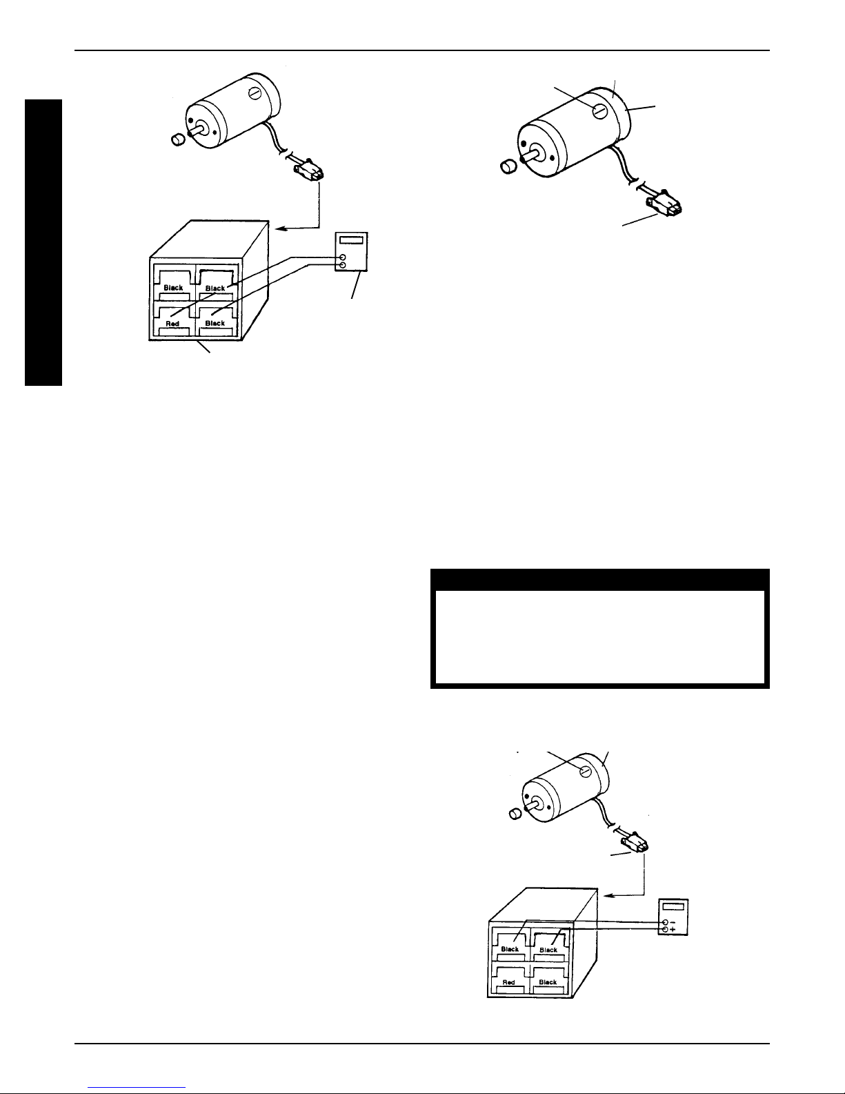
MOTOR TESTING (FIGURE 3)
NOTE: This procedure should only be performed on
wheelchairs with the conventional motor/gearbox assembly . For gearless/brushless motors, there are no serviceable parts. Return motor to manufacturer for testing.
T
R
O
U
B
L
E
S
H
O
O
T
I
N
G
NOTE: DO NOT fill hydrometer more than 3/4 full.
5. Draw up sufficient acid to cover float balls.
6. T ap lightly to remove air bubbles.
7. Number of floating balls indicates charge.
Number of Floating Balls
0 Discharged
1 25% Charged
2 50% Charged
3 75% Charged
4 100% Charged
* 5 Overcharged
* Check charging system.
8. Flush the liquid back into the same cell after reading
the float. Repeat this step until all cells have been properly read. A shorted or dead cell can be detected when
it is the only cell that does not charge.
1. On the 4-pin motor connector, locate the two (2) contacts in the red and black housings.
2. Set the digital multimeter to measure ohms (Ω).
3. Measure the resistance between the two (2) motor
contacts.
NOTE: A normal reading is between 1 and 5 ohms
(Ω). A reading of 0 ohms (Ω) or in excess of 15 ohms
(Ω) indicates a problem. High readings are generally
caused by bad connections and/or damaged brushes.
Contact authorized dealer or Invacare.
13
T
R
O
U
B
L
E
S
H
O
O
G
T
I
N
Motor Connector
Motor Connector
FIGURE 3 - MOTOR TESTING
Ohmmeter
Ohmmeter
MOTOR BRUSH INSPECTION
(FIGURE 4)
NOTE: This procedure should only be performed on wheelchairs with conventional motor/gearbox assembly .
There are two (2) contact brushes on STORM motors
located under the brush caps on the motor housing. If
these caps are hard to remove they are either overtightened or the motor has become very hot. Let motors cool. If caps still cannot be removed, it is recommended that the motor be sent to Invacare Technical
Services for inspection/repair.
NOTE: It is very important to note which way the brush
comes out of the motor. The brush MUST be placed into
the motor exactly the same way to ensure good contact
with the commutator.
1. Once the motor brush caps have been removed, pull
the brushes out of the motor. The end of the brushes
should be smooth and shiny and the spring should
not be damaged or discolored. If one or both of the
brushes are damaged, only the damaged or worn
brushes need be replaced. It is very important that
any time a brush is replaced, it must be “burned in”.
This is accomplished by running the motor for one
hour in each direction with a half hour break in-between. This should also be done with little or no load
on the motor, i.e., put the wheelchair up on blocks so
the drive (large) wheels do not contact the ground
and run the wheelchair. A motor with only one brush
replaced will only carry a small percentage of its rated
load capacity until the NEW brush is burned in.
TROUBLESHOOTINGPROCEDURE 2
Cap
Motor
4 Pin Motor Connector
FIGURE 4 - MOTOR BRUSH INSPECTION
ELECTRO-MECHANICAL PARKING
BRAKE TESTING (FIGURE 5)
NOTE: This procedure should only be performed on
wheelchairs with conventional motor/gearbox assembly .
1. On the four-pin motor connector, locate the side by
side connectors in the black housings.
2. Set the digital multimeter to read ohms (Ω).
3. Measure the resistance between the two (2) brake contacts. A normal reading is 100 ohms (Ω). A reading of 0
ohms (Ω) or a very high reading; i.e., MEG ohms or O.L.
(out of limit) indicates a shorted brake or an open connection respectively . If either condition exists, send the motor
to Invacare T echnical Service for inspection/repair.
CAUTION
A shorted electro-mechanical brake will
damage the brake output section in the controller. DO NOT connect a shorted electromechanical brake to a good controller module. A shorted brake MUST be replaced.
NOTE: A bad motor can damage the controller module
but a bad controller will NOT damage a motor.
Cap
4 Pin Motor Connector
FIGURE 5 - ELECTRO-MECHANICAL
PARKING BRAKE TESTING
Motor
Ohmmeter
14
PROCEDURE 3HARDWARE TORQUE SPECIFICATIONS
HARDWARE TORQUE SPECIFICATIONS
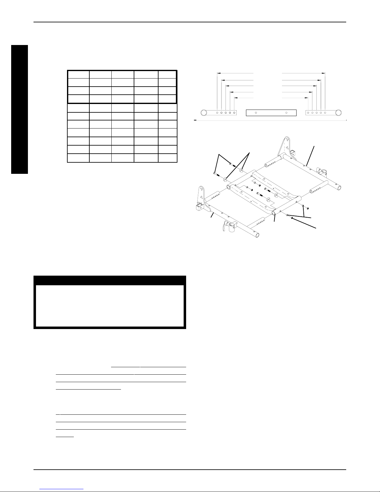
STANDARD SEAT FRAME
*Torque to
60 in-lbs
*Loctite and
*Loctite® and
T orque to
75 in-lbs
T orque to
75 in-lbs
T
O
R
Q
U
E
S
P
E
C
I
F
I
C
A
T
I
O
N
S
T orque to
156 in-lbs
**Torque to
156 in-lbs
**Torque to
156 in-lbs
NOTE:
* These torque specifications also apply to the adjustable seat frame assembly.
** These torque specifications also apply to the captains van seat and adjustable seat frame assemblies.
15
PROCEDURE 3 HARDWARE TORQUE SPECIFICATIONS
HARDWARE TORQUE SPECIFICATIONS
T
O
R
Q
U
E
*CAPTAINS VAN SEAT
*ADJUSTABLE SEAT FRAME
S
P
E
C
I
F
I
C
A
T
I
O
N
S
Torque to
156-in-lbs
Torque to
75-in-lbs
Torque to
156-in-lbs
Loctite and Torque to
75 in-lbs
Torque to
156-in-lbs
T orque to
156 in-lbs
Torque to
156-in-lbs
T orque to
156 in-lbs
* NOTE: For additional torque specifications, refer to the torque specifications drawing for the standard
seat frame assembly.
16
REAR OF
WHEELCHAIR
T orque to
156 in/lbs
(Torque to 156
in-lbs and back
off 1/4 turn)
BASE FRAME HARDWARE
TORQUE SPECIFICATIONS
Loctite and torque to
156 in/lbs
Loctite and
T orque to
156 in-lbs
PROCEDURE 3HARDWARE TORQUE SPECIFICATIONS
T orque to
156 in/lbs
T orque to
85 ft-lbs
T
O
R
Q
U
E
S
P
E
C
I
F
I
C
A
T
I
O
N
S
Loctite and
torque to
75 in/lbs
Wheel Halves -
T orque to
540 in-lbs
T orque to
156 in/lbs
Torque to 156 in/lbs
CONVENTIONAL MOTOR/GEARBOX
Adjustment
Screw
Torque
to 75 in-lbs.
FRONT OF
WHEELCHAIR
8 - inch Wheels -
Torque to 120 in-lbs
9 - inch Wheels -
Torque to 156 in-lbs
8 - inch - Torque to 18 in-lbs
9 - inch - Torque to 156 in-lbs
Wheel Halves
GEARLESS/BRUSHLESS MOTOR
NOTE: All torque specifications called out for the conventional motor/gearbox assembly are applicable to
the gearless/brushless motor except for the following:
Torque to 13 ft-lbs.
Torque to 25 in-lbs.
Torque to 13 ft-lbs.
17
ARMSPROCEDURE 4
This Procedure Includes the Following:
Replacing Armrest Pads - Captains Van Seats
Replacing Captains Van Seat Armrest Plate
WARNING
A
R
M
S
After ANY adjustments, repair or service
and BEFORE use, make sure that all attaching hardware is tightened securely - otherwise injury or damage may result.
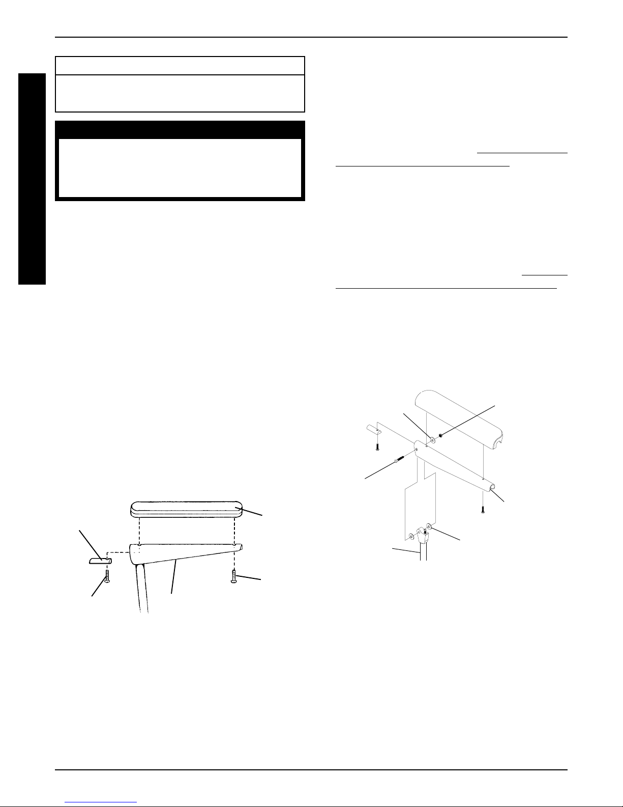
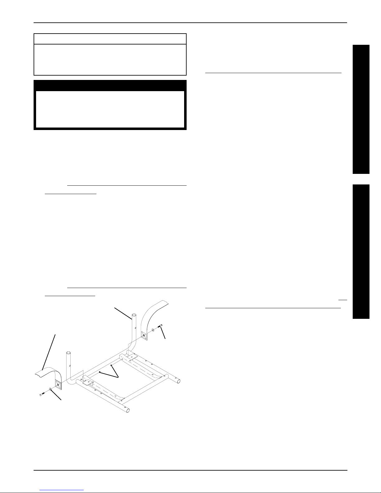
REPLACING ARMREST PADS CAPTAINS VAN SEATS (FIGURE 1)
1. Remove the mounting screws that secures the front
of the armrest pad to the armrest plate.
2. Remove the mounting screw that secures the rear of
the armrest pad and armrest insert to the armrest
plate.
3. Remove the existing armrest pad and position the
NEW armrest pad on the armrest plate.
4. Line up the mounting holes in the armrest insert, armrest plate and NEW armrest pad.
REPLACING CAPTAINS VAN SEAT
ARMREST PLATE (FIGURE 2)
1. If necessary , remove the three (3) mounting screws,
spacers and locknuts that secure the joystick mounting bracket to the armrest plate.
2. Remove armrest pad. Refer to
REST P ADS - CAPTAINS V AN SEATS in this procedure of the manual.
3. Remove the mounting screw, washers and locknut that
secure the existing armrest plate to the arm weldment.
4. Position the NEW armrest plate on the armrest weldment
and secure with the mounting screw, washers, and locknut. Refer to FIGURE 2 for correct hardware orientation.
5. Reinstall van style armrest pad. Refer to
ING ARMREST P ADS - CAPT AINS VAN SEA TS in
this procedure of the manual.
6. If necessary , reinstall the three (3) mounting screws,
spacers and locknuts that secure the joystick mounting bracket to the armrest plate.
7. Repeat STEPS 1-6 for the opposite armrest plate, if
necessary .
REPLACING ARM-
REPLAC-
5. Reinstall the rear mounting screw through the armrest insert, armrest plate and armrest pad and tighten
securely .
6. Reinstall the front mounting screw into the armrest
plate and NEW armrest pad and tighten securely.
FRONTREAR
Armrest
Insert
Mounting
Screw
FIGURE 1 - REPLACING ARMREST PADS -
CAPTAINS VAN SEATS
Armrest Plate
Armrest
Pad
Mount-
ing
Screw
Washer
Mounting
Screw
Arm
Weldment
FIGURE 2 - REPLACING CAPTAINS VAN SEAT
ARMREST PLATE
Washer
Locknut
Armrest
Plate
18
UPHOLSTERY/POSITIONING STRAP PROCEDURE 5
This Procedure Includes the Following:
Replacing Seat Positioning Strap - Captains Van
Seats
Replacing Back Upholstery
WARNING
After ANY adjustments, repair or service
and BEFORE use, make sure that all attaching hardware is tightened securely - otherwise injury or damage may result.
REPLACING SEAT POSITIONING
STRAP - CAPTAINS VAN SEATS
(FIGURE 1)
1. Remove the van style seat from the van seat frame.
Refer to INST ALLING/REMOVING CAPTAINS V AN
SEA T ASSEMBLY in PROCEDURE 6 of this manual.
2. Remove the two (2) rear mounting screws, washers,
and locknuts that secure the seat positioning straps
to the van seat frame.
NOTE: The washer is positioned between the seat positioning strap and the mounting screw.
3. Secure the NEW seat positioning strap halves with
the mounting screws, washers and locknuts to the
van seat frame and torque to 75-inch pounds.
4. Reinstall the van style seat to the van seat frame.
Refer to
SEA T ASSEMBLY in PROCEDURE 6 of this manual.
Seat Positioning
INST ALLING/REMOVING CAPTAINS V AN
Van Seat Frame
Strap
REAR OF SEAT
FRAME
Mounting
Screw
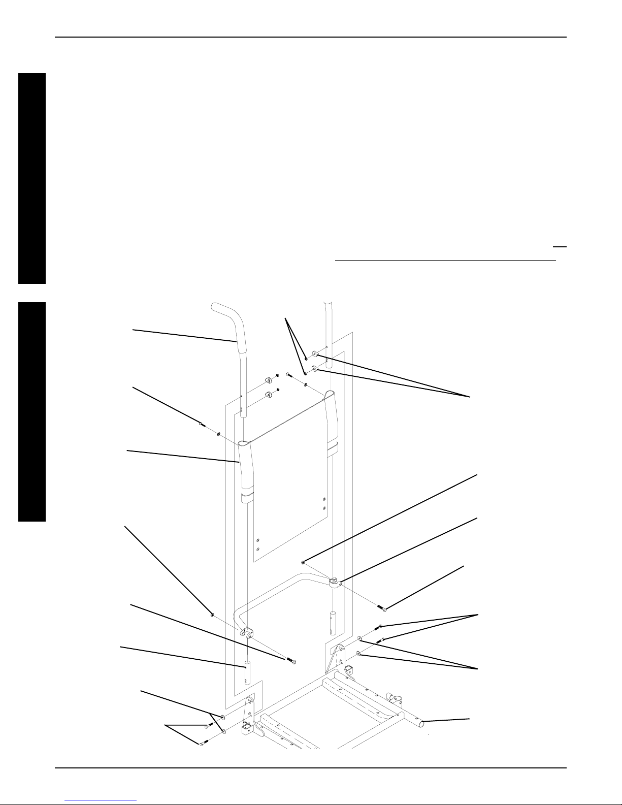
REPLACING BACK UPHOLSTERY
(FIGURE 2)
1. Remove one (1) armrest from the wheelchair. Refer to
INST ALLING/REMOVING FLIP BACK ARMRESTS in
PROCEDURE 4 of the owner’s manual, 1081227.
2. If applicable, remove the two (2) mounting screws
and locknuts that secure the spreader bar to the back
canes.
3. Remove the two (2) mounting screws and washers
that secure the existing back upholstery to the back
canes.
4. Cut the tie-wraps that secure the bottom of the existing back upholstery to the back canes.
NOTE: Note the back angle before disassembly for proper
reinstallation.
5. On the side of the wheelchair that the armrest was
removed, remove one (1) of the mounting screws,
washer, spacer, and locknut that secures the back
cane to the seat frame.
NOTE: T o avoid losing the insert in each back cane, thread
the mounting screw just removed through the cane from
the inside of the wheelchair to hold the insert in place.
6. Remove the other mounting screw , washer , spacer,
and locknut that secures the back cane to the seat
frame.
7. Slide the back cane out of the spreader bar (If applicable) and the existing back upholstery .
8. Remove other armrest from the chair. Refer to
STALLING/REMOVING FLIP BACK ARMRESTS in
PROCEDURE 4 of the owner’s manual, 1081227.
9. Repeat STEPS 5-7 for the opposite side of the wheelchair.
10. Slide the other back cane out of the spreader bar (if
applicable) and the existing back upholstery .
IN-
U
P
H
O
L
S
T
E
R
Y
P
O
S
I
T
I
O
N
I
N
G
S
T
R
A
P
Locknuts
Washer
FIGURE 1 - REPLACING SEAT POSITIONING
STRAP - CAPTAINS VAN SEATS
FRONT OF SEAT
FRAME
11. Slide one(1) back cane into NEW back upholstery
and through spreader bar (if applicable).
12. Secure back cane to the seat frame from the outside
of the wheelchair with the existing two (2) mounting
screws, washers, spacers, and locknuts. Use Loctite
242 and torque to 75-in/lbs.
13. Repeat STEPS 11-12 for opposite back cane.
14. Secure the top of the NEW back upholstery to the
back canes with the two (2) existing mounting screws.
19
UPHOLSTERY/POSITIONING STRAPPROCEDURE 5
NOTE: When replacing the back upholstery, back assembly or changing back height, follow these guidelines
for spreader bar height:
STANDARD MODELS
U
P
H
O
L
S
T
E
R
Y
P
O
S
I
T
I
O
N
I
N
G
S
T
R
A
P
BACK HEIGHT u SPREADER BAR
HEIGHT
16-inches* 5-inches
17-inches* 5-inches
18-19-inches* 7-inches
20-24-inches 7-inches
NOTE: Spreader Bar required on ALL back heights between 20-24-inches. *Spreader bar required on back
heights 16,17,18, or 19 ONL Y if the width or depth of the
chair exceeds 19-inches.
uHeight of Spreader Bar from Bottom of Back
Canes to Top of Spreader Bar Clamp.
Back Cane
(STEPS 3, 12)
Mounting
Screw
(STEPS 3, 14)
Washer
(STEPS 3, 14)
Back
Upholstery
(STEPS 3, 7)
Locknut
(STEP 2)
HEAVY DUTY MODELS
NOTE: Spreader bar required on all back heights.
BACK HEIGHT u SPREADER BAR
HEIGHT
16-17-inches 5-inches
18-24-inches 7-inches
uHeight of Spreader Bar from Bottom of Back
Canes to Top of Spreader Bar Clamp.
15. If applicable, reposition the spreader bar at the correct
height for the corresponding back height and torque
the mounting hardware to 60-in/lbs.
16. Reinstall the armrest onto the wheelchair. Refer to INST ALLING/REMOVING FLIP BACK ARMRESTS in
PROCEDURE 4 of the owner’s manual, 1081227.
Locknuts
(STEPS 5, 6)
Spacers
(STEPS 5, 6)
Locknut
(STEP 2)
Spreader Bar
(STEPS 2, 7, 16)
Mounting
Screw
(STEP 2)
Insert
Washers
(STEPS 5, 6)
Mounting Screws
Torque to 75 in/lbs
(STEPS 5, 6)
FIGURE 2 - REPLACING BACK UPHOLSTERY
Mounting Screw
Torque to 60 in/lbs
(STEP 2)
Mounting
Screws
(STEPS 5, 6)
Washers
(STEPS 5, 6)
Seat Frame
20
PROCEDURE 6SEAT FRAME
This Procedure includes the following:
Preparation for Removing/Installing Seat Frame
(Standard Frame, Adjustable Frame,
and Captains Van Seat) ............................Page 21
Replacing Exact Same Size Standard
Seat Frame ..............................................Page 22
Removing/Installing Standard Seat Frame
Sub-Assembly .........................................Page 22
Changing Seat Depth ...............................Page 23
Changing Seat Width (Standard and Adjustable
Seat Frame) ............................................. Page 25
Installing/Removing Adjustable Seat Frame
Sub-Assembly and/or Component
Replacement ........................................... Page 26
Installing/Removing Captains Van Seat
Assembly ................................................Page 28
Replacing Captains Van Seat and/or Captains
Van Seat Frame .......................................Page 28
Converting From Standard Seat Frame to Adjust-
able Seat Frame or Vice V ersa..................Page 29
Converting From Adjustable Seat Frame to
Captains Van Seat or V ice Versa...............Page 29
Converting From Standard Seat Frame to Cap-
tains Van Seat or V ice Versa.....................Page 30
Removing/Installing Seat Pan ..................Page 30
Mounting Plate - Seat Angle Adjustment and
Installation Orientation .............................Page 31
WARNING
After ANY adjustments, repair or service and
BEFORE use, make sure that all attaching
hardware is tightened securely - otherwise
injury or damage may result.
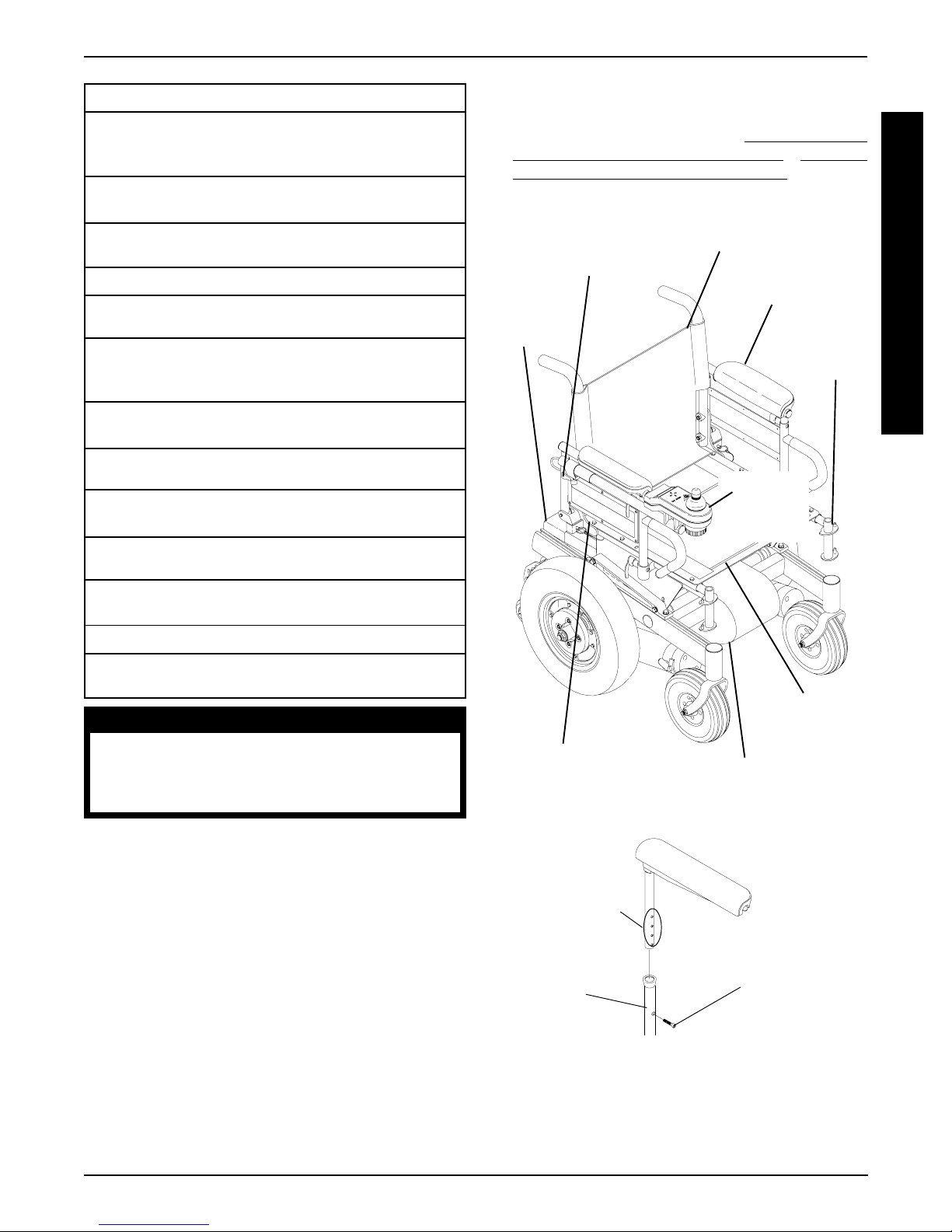
1. Remove footrest assemblies. Refer to PROCEDURE
4 in of the owner’s manual, 1081227.
2. Remove battery box(es). Refer to
MOVING GROUP 24 BATTERY BOXES or INSTALLING/REMOVING 22NF BATTERY BOX in PROCEDURE 9 of this manual.
Adjustment Lock
Lever for Joystick
(STEP 4)
Battery
Box(es)
(STEP 2)
Seat Positioning
Strap (STEP 7)
Back Upholstery
(STEP 10)
Controller, Left/Right Motor
Connectors (STEPS 8,9)
INSTALLING/RE-
Flip Back
Armrests
(STEP 6A)
Footrest
Location
(STEP 1)
Joystick
(STEPS
3,5)
Seat Pan
(STEP 7)
S
E
A
T
F
R
A
M
E
NOTE: The procedures in this section of the manual refer to NON-RECLINER seat frames only , EXCEPT Seat
Angle Adjustment. For recliner seat frames, refer to PROCEDURE 14 of this manual.
PREPARATIONS FOR REMOVING/
INSTALLING SEAT FRAME
(STANDARD FRAME, ADJUSTABLE
FRAME, AND CAPTAINS VAN SEAT)
(FIGURE 1)
NOTE: When installing/replacing components of the wheelchair, refer to the individual procedure for correct use of
LOCTITE 242 and torque specifications or PROCEDURE
3 of this manual.
NOTE: T o reinstall these components, reverse the following steps.
STEP 6B
Height
Adjustment
Holes
Captains
Van Seat
Base
FIGURE 1 - PREPARATIONS FOR REMOVING/
INSTALLING SEAT FRAME (STANDARD FRAME,
ADJUSTABLE FRAME, AND CAPTAINS VAN SEAT)
21
Socket
Screw
PROCEDURE 6 SEAT FRAME
3. Cut tie wraps and disconnect joystick from controller.
4. Turn the lever on the adjustment lock to release the
adjustment lock from the joystick mounting tube.
5. Remove the joystick from the wheelchair.
S
E
6. Perform one (1) of the following:
A
T
F
R
A
M
E
A. STANDARD OR ADJUSTABLE SEAT
FRAMES - Remove the flip-back armrests from
the wheelchair. Refer to
FLIP BACK ARMRESTS in PROCEDURE 4 of
the owner’s manual, 1081227.
B. CAPT AINS VAN SEAT - Remove the mounting
screw that secures the armrest to the van seat
frame. Repeat for opposite side.
7. For standard and adjustable seat frames, remove the
seat pan (including seat positioning straps). Refer to
REMOVING/INSTALLING SEAT P AN in this procedure
of the manual.
8. Disconnect battery and left/right motor connectors from
the controller. Refer to
NESS in PROCEDURE 10 of this manual.
INSTALLING/REMOVING
REPLACING WIRING HAR-
4. Reinstall the components previously removed in STEP
1. Perform the instructions outlined in
FOR REMOVING/INSTALLING SEAT FRAME (ST ANDARD FRAME, ADJUST ABLE FRAME, AND CAPT AINS V AN SEAT) in this procedure of the manual.
PREPARATIONS
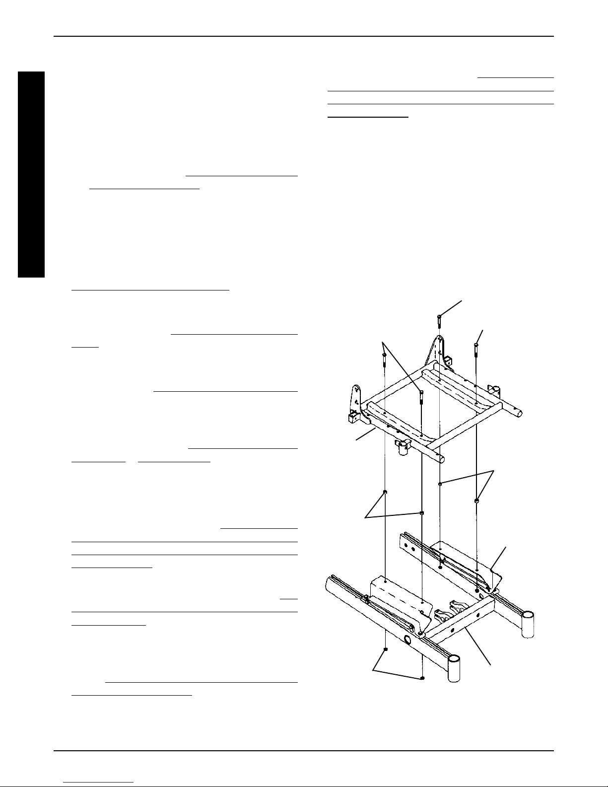
REMOVING/INSTALLING
STANDARD SEAT FRAME
SUBASSEMBLY (FIGURE 2)
Removing
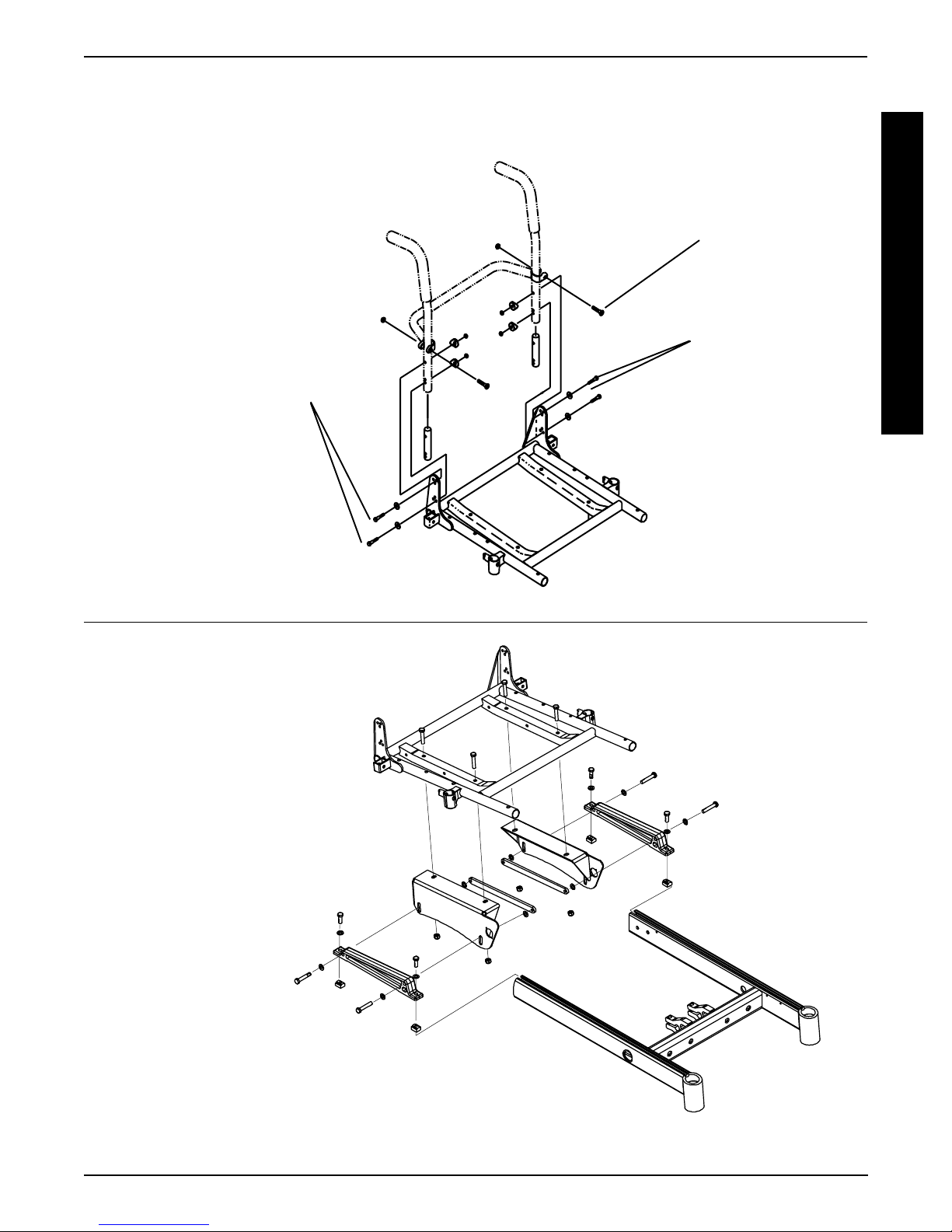
1. Remove the four (4) mounting screws, locknuts and
spacers, if applicable, that secure the standard seat
frame subassembly to the seat mounting plates.
2. Remove the existing standard seat frame.
Mounting Screws
Mounting Screws
(Torque to 156-
inch pounds)
(Torque to 156-
inch pounds)
9. Remove tie-wraps that secures the wiring harness to
the seat frame and the charger cable from its mounting bracket. Refer to
in PROCEDURE 10 of this manual.
10. For standard and adjustable seat frames, remove the
back upholstery (including back canes and spreader
bar, if applicable). Refer to
HOLSTERY in PROCEDURE 5 of the manual.
REPLACING WIRING HARNESS
REPLACING BACK UP-
REPLACING EXACT SAME SIZE
STANDARD SEAT FRAME
1. Perform the instructions outlined in PREPARA TIONS
FOR REMOVING/INSTALLING SEAT FRAME (ST ANDARD FRAME, ADJUST ABLE FRAME, AND CAPT AINS V AN SEA T) in this procedure of the manual.
2. Remove the existing standard seat frame subassembly and install the NEW standard frame. Refer to
MOVING/INST ALLING STANDARD SEAT FRAME
SUBASSEMBLY in this procedure of the manual.
3. FOR 12-15-INCH SEAT DEPTHS ONLY: Remove
the CJ back brackets from the existing standard seat
frame and install onto the NEW standard seat frame.
Refer to
ETS FROM SEAT FRAME in this procedure of the
manual.
REMOVING/INSTALLING CJ BACK BRACK-
RE-
Standard
Seat
Assembly
Spacer
(16-inch Wide
Only)
Locknuts
FIGURE 2 - REMOVING/INSTALLING
STANDARD SEAT FRAME SUB-ASSEMBLY
Base Frame
Spacer
(16-inch
Wide Only)
Seat
Mounting
Plate
22

PROCEDURE 6SEAT FRAME
Installing
1. Position NEW standard seat frame subassembly on
seat mount plates.
2. Secure NEW standard seat frame subassembly onto
seat mounting plates with the existing four (4) mounting screws, locknuts and spacers, if applicable. T orque
to 156-inch pounds.
CHANGING SEAT DEPTH
Standard Seat Frame
NOTE: Review the chart below. This will determine the components needed to obtain the desired seat depth.
COMPONENT IDENTIFICATION TABLE
FOR STANDARD SEAT FRAME
SEAT FRAME COMPONENTS
CJ BACK SEA T
SEA T BRACKETS SEAT FRAME
DEPTH REQUIRED P AN DEPTH
12-inches
to YES 17-inch 16-inch deep
15-inches
16-inches NO 16-inch 16-inch deep
17-inches NO 17-inch 16-inch deep
18-inches NO 18-inch 18-inch deep
19-inches NO 19-inch 18-inch deep
20-inches NO 20-inch 20-inch deep
21-inches NO 21-inch 20-inch deep
22-inches NO 22-inch 22-inch deep
1. Find current seat depth in left hand column in the chart.
2. Follow that row to right under seat frame components.
3. Verify and note the components of the current seat depth.
4. Repeat STEPS 1-3 for your desired seat depth.
B. If the desired change only requires a NEW seat
pan, refer to
in this procedure of the manual.
C. For all other seat depth changes, perform the fol-
lowing:
l
PREPARATIONS FOR REMOVING/INSTALLING SEAT FRAME (STANDARD
FRAME, ADJUST ABLE FRAME, AND CAPT AINS VAN SEAT) in this procedure of the
manual.
Perform one (1), two (2), or all three (3) of the procedures listed below depending on the components required for the desired seat depth determined from STEPS 1-5:
REMOVING/INST ALLING CJ BACK BRACK-
l
ETS in this procedure of the manual.
l
REMOVING/INST ALLING STANDARD SEAT
SUBASSEMBL Y in this procedure of the
manual.
l
REMOVING/INSTALLING SEAT P AN in this
procedure of the manual.
After completing the procedure(s) listed above, perform the steps outlined in
REMOVING/INST ALLING SEAT FRAME (ST ANDARD FRAME, ADJUSTABLE FRAME, AND
CAPTAINS VAN SEAT) to complete the desired
seat depth change.
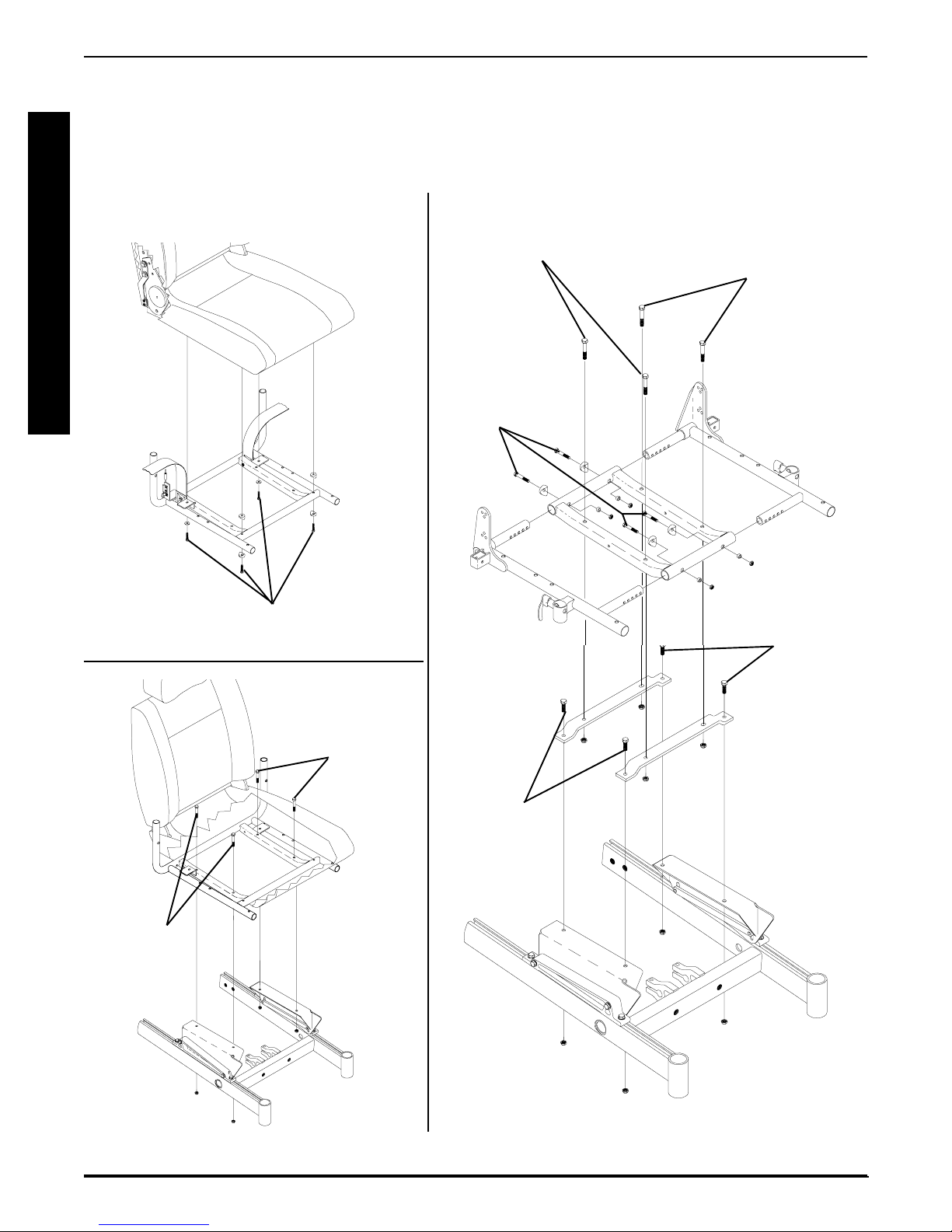
Adjustable Seat Frame (FIGURE 3)
REMOVING/INSTALLING SEA T PAN
PREP ARA TIONS FOR
NOTE: Review the chart below. This will determine the components needed to obtain your desired seat depth.
COMPONENT IDENTIFICATION TABLE
FOR STANDARD SEAT FRAME
SEAT FRAME COMPONENTS
CJ BACK
SEA T BRACKETS SEAT SIDE CENTER
DEPTH REQUIRED P A N FRAME FRAME
S
E
A
T
F
R
A
M
E
5. Compare existing components of the current seat depth
and the required components for the desired seat depth.
6. Perform one (1) of the following:
A . If the current seat depth and the desired seat depth
is within the 12-15-inch seat depth range, this change
can be accomplished by repositioning the back
canes on the CJ back brackets. Refer to
ING SEA T DEPTH BETWEEN 12-15-INCHES in
this procedure of the manual.
CHANG-
12-inches
to YES 17-inch Short Short
15-inches
16-inches NO 16-inch Short Short
17-inches NO 17-inch Short Short
18-inches NO 18-inch Medium Short
19-inches NO 19-inch Medium Short
20-inches NO 20-inch Long Long
21-inches NO 21-inch Long Long
22-inches NO 22-inch X-Long Long
NOTE: Note the four (4) different lengths of side frames
short, medium, long, and X-long, as well as the two different
center frames, short and long. These components are interchanged to obtain the various different seat depths.
23

PROCEDURE 6 SEAT FRAME
1. Find current seat depth in left hand column in the chart.
2. Follow that row to right under seat frame components.
3. Verify and note the components of the current seat depth.
S
4. Repeat STEPS 1-3 for the desired seat depth.
E
5. Compare existing components of the current seat depth
A
and the required components for the desired seat depth.
T
T o adjust the depth of the seat on the wheelchair, use
F
the following guidelines:
R
If the current seat depth is and the desired seat depth are
A
within the 12-15-inch seat depth range, this change can be
M
accomplished by repositioning the back canes on the CJ
E
back brackets. Refer to
TWEEN 12-15-INCHES in this procedure of the manual.
If the desired change only requires a NEW seat pan, refer to
REMOVING/INST ALLING SEAT P AN in this procedure of
the manual.
If the desired change requires the removal/installation of CJ
back brackets, refer to
BRACKETS in PROCEDURE 8 of this manual.
If the desired change requires a new side frame, and/or new
center frame, perform the following steps:
CHANGING SEAT DEPTH BE-
REMOVING/INST ALLING CJ BACK
NOTE: If seat width adjustment is also desired, refer to CHANGING SEA T WIDTH in this procedure
of the manual for mounting hole locations and allowable seat width/seat depth combinations.
Mounting
Screws
(Torque to 75-
inch pounds)
Coved
Washers
Side Frame
Mounting Screws
(Torque to 156-
inch pounds)
Side
Frame
Spacers
Locknuts
Center
Frame
A . Perform the instructions outlined in
REMOVING/INST ALLING PREPARATIONS FOR
STANDARD FRAME, ADJUSTABLE FRAME, AND
CAPT AINS VAN SEAT in this procedure of the
manual.
SEA T FRAME
NOTE: Note the mounting hole position of the side
frame for proper installation of the NEW side frame.
B. Remove the two (2) mounting screws, coved wash-
ers, spacers, and locknuts that secure the side frame
to the center frame.
C. Remove the side frame from the center frame.
D. Repeat STEPS A and B for opposite side frame.
If the desired seat depth requires a new center
frame, determined in STEPS 1-5 perform STEPS
E - G, otherwise proceed to STEP H.
E. Remove the four (4) mounting screws that secure
the EXISTING center frame to support brackets.
F. Remove existing center frame from seat mount
plates.
G. Secure NEW center frame to support brackets with
the existing four (4) mounting screws and locknuts.
T orque to 156-inch pounds.
H. Secure NEW side frame to the center frame at the
position noted previously. Torque to 75-inch pounds.
Support Brackets
FIGURE 3- CHANGING SEAT DEPTH -
ADJUSTABLE SEAT FRAME
Changing Seat Depth Between 12 and 15Inches (FIGURE 4)
NOTE: There are two (2) sizes of CJ back brackets. Refer
to the following chart to determine if the seat depth required
is obtainable by repositioning the back canes only , or if the
CJ back brackets must be replaced.
CJ BACK BRACKET (SEAT DEPTH) RANGES
12 and 13-inches OR 14 and 15-inches
If seat depth required is within seat depth range of
the original CJ back brackets, only the back canes
need to be repositioned. Refer to the following procedure.
If the seat depth required is NOT within the seat depth
range of the original CJ back brackets, the CJ back
brackets must be replaced before repositioning the
back canes. Refer to
BACK BRACKETS in PROCEDURE 8 of this manual.
REMOVING/INSTALLING CJ
24

PROCEDURE 6SEAT FRAME
1. Remove the armrests from the wheelchair. Refer to INST ALLING/REMOVING FLIP BACK ARMRESTS in
PROCEDURE 4 of the owner’s manual, 1081227.
2. Cut the tie wraps that secure the back upholstery to the
CJ back brackets.
3. Pull the bottom of the back upholstery away from the
rear of the seat pan.
4. Remove mounting screw, washer and coved washer
from the top mounting hole of the CJ back bracket and
back cane.
NOTE: Before removing the back canes from the CJ back
brackets, note the BACK ANGLE for reinstallation.
NOTE: T o avoid losing the insert in each back cane, line up
the holes in the insert with the holes in the back cane and
start one of the screws through the cane from the inside of
the wheelchair to hold the insert in place.
5. Remove the mounting screw, washer and coved
washer from the bottom mounting hole of the CJ back
bracket and the back cane.
6. Reposition the back cane to the desired seat depth
and angle. If changing the back angle as well, refer to
BACK ANGLE ADJUSTMENT in PROCEDURE 8 of
this manual.
7. Secure bottom of the back upholstery to the seat pan.
8. Secure the bottom of the back upholstery to the CJ
back brackets with new tie wraps.
9. Use Loctite 242 and torque the mounting screws to
75-inch pounds.
10. Repeat the STEPS 1-9 for the opposite back cane.
Back Cane
Coved
Washers
1 1. Reinstall the armrests onto the wheelchair . Refer to
ST ALLING/REMOVING FLIP BACK ARMRESTS in
PROCEDURE 4 of the owner’s manual, 1081227.
IN-
CHANGING SEAT WIDTH
(STANDARD AND ADJUSTABLE
SEAT FRAME)
Standard Seat Frame
NOTE: If changing seat width below 16-inches wide, you must
convert to an adjustable seat frame. Refer to CONVERTING FROM STANDARD TO ADJUSTABLE SEAT
FRAME OR VICE VERSA in this procedure of the manual.
For all changes above 16-inches wide, perform the outlined
steps.
1. Perform the instructions outlined in PREPARATIONS
FOR REMOVING/INSTALLING SEAT FRAME (ST ANDARD FRAME, ADJUSTABLE FRAME, AND CAPTAINS VAN SEA T) in this procedure of the manual.
2. Remove the existing standard seat frame subassembly and install the NEW standard frame. Refer to
MOVING/INST ALLING STANDARD SEAT FRAME
SUBASSEMBLY in this procedure of the manual.
3. FOR 12-15-INCH SEAT DEPTHS ONLY: Remove
the CJ back brackets from the existing standard seat
frame and install onto the NEW standard seat frame.
Refer to
ETS in PROCEDURE 8 of t his manual.
4. Reinstall the components previously removed in STEP
1. Perform the instructions outlined in
FOR REMOVING/INSTALLING SEAT FRAME (ST ANDARD FRAME, ADJUST ABLE FRAME, AND CAPT AINS V AN SEA T) in this procedure of the manual.
Adjustable Seat Frame (FIGURE 5)
REMOVING/INSTALLING CJ BACK BRACK-
PREP ARATIONS
RE-
S
E
A
T
F
R
A
M
E
CJ Back
Bracket
Washers
Mounting Screws
FIGURE 4 - ADJUSTING SEAT DEPTH -
CHANGING SEAT DEPTH BETWEEN 12 AND
15-INCHES
Threaded
Insert
Seat
Frame
NOTE: If changing seat width above 16-inches wide, you
must convert to a standard seat frame. Refer to CONVERTING FROM STANDARD TO ADJUSTABLE SEAT
FRAME OR VICE VERSA in this procedure of the manual.
For all changes below 16-inches wide, perform the outlined
steps.
1. Perform the instructions outlined in PREPARATIONS
FOR REMOVING/INSTALLING SEAT FRAME (ST ANDARD FRAME, ADJUSTABLE FRAME, AND CAPTAINS VAN SEA T) in this procedure of the manual.
2. Review the following chart for the allowable seat width
and seat depth combinations for the adjustable seat
frame.
25
PROCEDURE 6 SEAT FRAME
ALLOW ABLE SEAT WIDTH AND DEPTH COMBINA TIONS
FOR ADJUST ABLE SEA T FRAME
SEAT WIDTH
S
E
A
T
F
R
A
M
E
12 ✓✓✓✓✓
S
13 ✓✓✓✓✓
E
14 ✓✓✓✓✓
A
15 ✓✓✓✓✓
T
16 ✓✓✓✓✓
17 N/A N/A ✓✓✓
D
18 N/A N/A ✓✓✓
E
19 N/A N/A ✓✓✓
P
20 N/A N/A ✓✓✓
21 N/A N/A ✓✓✓
T
22 N/A N/A ✓✓✓
H
NOTE: The seat widths and seat depths enclosed in the
outlined box will require the use of CJ back brackets and a
17-inch deep seat pan.
3. Remove the two (2) mounting screws, coved washers,
spacers, and locknuts that secure the side frame to the
center frame.
4. Adjust side frame to desired width determined from
STEP 2. See DETAIL “A” for proper mounting hole
position.
5. Secure side frame to center frame with existing mounting screws, coved washers, spacers, and locknuts.
Torque mounting screws to 75-inch pounds.
12 13 14 15 16
WARNING
Both side frames MUST be adjusted to the same
mounting hole position to maintain proper weight
balance of user and seat frame. If weight is not
balanced, injury to the assistant and/or user and
damage to the wheelchair may result.
6. Repeat STEPS 3-5 for opposite side frame.
7. Perform one (1) of the following:
A. For adjusting the seat width only, perform the in-
structions outlined in
MOVING/INST ALLING SEAT FRAME (STANDARD FRAME, ADJUSTABLE FRAME, AND
CAPTAINS VAN SEAT) in this procedure of the
manual.
NOTE: When performing the steps outlined in
PREPARATIONS FOR REMOVING/INSTALLING SEAT FRAME (STANDARD FRAME, ADJUSTABLE FRAME, AND CAPTAINS VAN
SEAT) the seat pan, seat cushion, back upholstery and spreader bar (if applicable), will need to
be replaced. Spreader bars are only required on
seat depths greater than 19-inches.
PREP ARA TIONS FOR RE-
B. For all other changes regarding seat frame changes,
refer back to the starting procedure to complete the
desired change.
DETDET
AIL AIL
““
AIL
“
AIL AIL
““
Center
Frame
A”A”
A”
A”A”
Side Frame
Spacers
Locknut
DET
DETDET
12-inches
13-inches
14-inches
15-inches
16-inches
STEPS 3-6STEPS 3-6
STEPS 3-6
STEPS 3-6STEPS 3-6
Mounting
Screws
Side
Frame
FIGURE 5 -CHANGING SEA T WIDTH - ADJUSTABLE
Coved
Washers
SEA T FRAME
INSTALLING/REMOVING
ADJUSTABLE SEAT FRAME
SUBASSEMBLY AND/OR
COMPONENT REPLACEMENT
(FIGURE 6)
Converting from Adjustable Seat Frame to
Standard Seat Frame or Captains Van Seat
NOTE: This section must be performed in conjunction with
a starting procedure.
1. Remove the four (4) mounting screws that secure the
two (2) support brackets of the adjustable seat frame
subassembly to the seat mounting plates.
2. T o complete conversion, refer back to the starting procedure to complete the desired change.
Converting from Standard Seat Frame or
Captains Van Seat To Adjustable Seat Frame
NOTE: This section must be performed in conjunction with
a starting procedure.
NOTE: When converting the seat frame, you will need a
seat pan, seat cushion, back upholstery and spreader bar (if
applicable). Spreader bars are only required on seat depths
of greater than 19-inches.
S
E
A
T
F
R
A
M
E
26
PROCEDURE 6SEA T FRAME
1. Secure both support brackets to the seat mounting plates
with four (4) mounting screws and locknuts. Torque
mounting screws to 156-inch pounds.
2. Secure the center frame to the support brackets with
four (4) mounting screws, locknuts, and spacers. T orque
to 156-inch pounds.
3. Insert the side frame into the center frame and secure
with mounting screw, coved spacer, spacer, and locknut. T orque to 75-inch pounds. Repeat for opposite side
frame.
Mounting Screws
(Torque to 156-inch pounds)
Mounting Screws
(Torque to 75-inch
pounds)
Coved Washer
Center Frame
Component Replacement
1. Perform the instructions outlined in
FOR REMOVING/INSTALLING SEAT FRAME (ST ANDARD FRAME, ADJUSTABLE FRAME, AND CAPT AINS V AN SEAT) in this procedure of the manual.
PREPARATIONS
NOTE: Note the mounting hole position of the current side
frame(s) for proper installation of the NEW side frame(s).
2. Remove the two (2) mounting screws, coved spacers,
spacers, and locknuts that secure the side frame to the
center frame.
Mounting Screws
(Torque to 156-inch pounds)
Side Frame
S
E
A
T
F
R
A
M
E
Side Frame
Support
Bracket
Mounting Screws
(Torque to 156-inch
pounds)
Mounting
Plate
Spacer
Locknuts
Mounting Screws
(Torque to 156-inch
pounds)
Support
Bracket
Locknuts
Base
Frame
Locknuts
FIGURE 6 - INST ALLING/REMOVING ADJUSTABLE SEA T FRAME SUBASSEMBLY AND/OR COMPONENT
REPLACEMENT
27
PROCEDURE 6 SEAT FRAME
3. Perform one (1) of the following:
A. If center frame needs replaced, repeat STEP 2 for
opposite side frame and proceed to STEP 4.
S
E
A
T
B. If opposite side frame needs replaced, repeat STEP
2, then proceed to STEP 6. Otherwise proceed to
STEP 6.
4. Remove the four (4) mounting screws and locknuts that
secure the center frame to the support brackets.
F
5. Secure NEW center frame to support brackets with ex-
R
A
M
E
isting four (4) mounting screws and locknuts. T orque to
156-inch pounds.
WARNING
Both side frames MUST be adjusted to the same
mounting hole position to maintain proper weight
balance of user and seat frame. If weight is not
balanced, injury to the assistant and/or user and
damage to the wheelchair may result.
6. Install new/existing side frame(s) into new/existing center frame at the mounting position previously noted.
Torque to 75-inch pounds.
7. Perform the instructions outlined in
FOR REMOVING/INSTALLING SEAT FRAME (ST ANDARD FRAME, ADJUST ABLE FRAME, AND CAPT AINS V AN SEAT) in this procedure of the manual.
PREPARATIONS
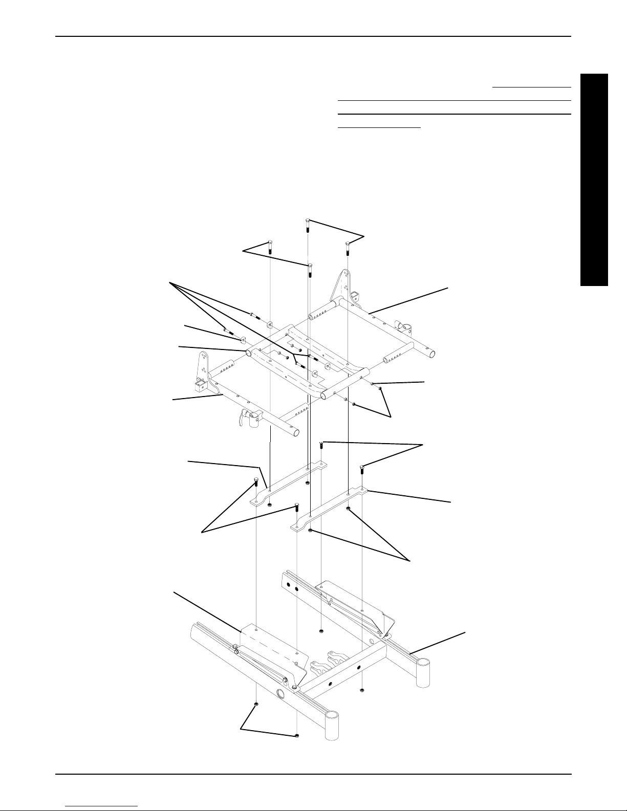
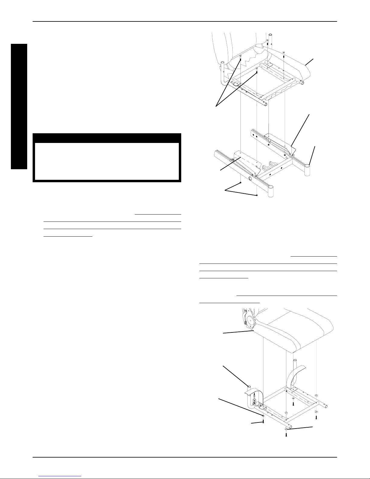
INSTALLING/REMOVING CAPTAINS
VAN SEAT ASSEMBLY (FIGURE 7)
Installing Captains Van Seat
1. Position the captains van seat on the seat mounting
plates at the position shown in FIGURE 7.
2. Line up mounting holes in the captains van seat frame
and the mounting holes in the seat mounting plates.
3. Secure the captains van seat to the seat mounting plates
with four (4) mounting screws, and locknuts. Torque to
156-inch pounds.
Captains Van
Seat
Seat Mounting
Mounting
Screws
(Torque to 156-
inch pounds)
Seat
Mounting
Plate
Locknuts
FIGURE 7 - REMOVING/INST ALLING CAPTAINS VAN
SEA T ASSEMBL Y
Plate
Base Frame
REPLACING CAPTAINS VAN SEAT
AND/OR CAPTAINS VAN SEAT
FRAME (FIGURE 8)
1. Perform the instructions outlined in PREPARATIONS
FOR REMOVING/INSTALLING SEAT FRAME (ST ANDARD FRAME, ADJUST ABLE FRAME, AND CAPT AINS V AN SEAT) in this procedure of the manual.
2. Remove the captains van seat assembly from the wheelchair. Refer to
V AN SEAT ASSEMBL Y in this procedure of the manual.
Captains
Van Seat
INST ALLING /REMOVING CAPTAINS
Removing Captains Van Seat
1. Remove the four (4) mounting screws and locknuts that
secure the captains van seat to the seat mounting plates.
2. Remove captains van seat from seat mounting plates.
Captains
Van Seat
Frame
Washer
Mounting Screw
(Torque to 75-inch
pounds)
FIGURE 8 - REPLACING CAPT AINS VAN SEA T AND/
OR CAPT AINS VAN SEAT FRAME
28
Spacer
 Loading...