


International Comfort Products CCH9, CCH6, HCH9, TCH9, HCH6 Installation Manual
...INSTALLATION INSTRUCTIONS
R−410A Two−Stage Split System Heat Pumps
CCH9, HCH9, TCH9
CCH6, HCH6, TCH6
These instructions must be read and understood completely before attempting installation.
Safety Labeling and Signal Words
DANGER, WARNING, CAUTION, and NOTE
The signal words DANGER, WARNING, CAUTION, and NOTE are used to identify levels of hazard seriousness. The signal word DANGER is only used on product labels to signify an immediate hazard. The signal words WARNING, CAUTION, and NOTE will be used on product labels and throughout this manual and other manuals that may apply to the product.
DANGER − Immediate hazards which will result in severe personal injury or death.
WARNING − Hazards or unsafe practices which could result in severe personal injury or death.
CAUTION − Hazards or unsafe practices which may result in minor personal injury or product or property damage.
NOTE − Used to highlight suggestions which will result in enhanced installation, reliability, or operation.
Signal Words in Manuals
The signal word WARNING is used throughout this manual in the following manner:
!WARNINGWARNING
The signal word CAUTION is used throughout this manual in the following manner:
!CAUTION
Signal Words on Product Labeling
Signal words are used in combination with colors and/or pictures on product labels.
TABLE OF CONTENTS
Safety Considerations . . . . . . . . . . . . . . . . . . . . . . . . . . . 2
Installation Recommendations . . . . . . . . . . . . . . . . . . . 2
Installation . . . . . . . . . . . . . . . . . . . . . . . . . . . . . . . . . . . . . 2
Start−up Procedure . . . . . . . . . . . . . . . . . . . . . . . . . . . . . 7
System Functions & Sequence of Operation . . . . . . . 9
Defrost . . . . . . . . . . . . . . . . . . . . . . . . . . . . . . . . . . . . . . . 10
Troubleshooting . . . . . . . . . . . . . . . . . . . . . . . . . . . . . . . 11
Status Codes . . . . . . . . . . . . . . . . . . . . . . . . . . . . . . . . . 15
R−410A Quick Reference Guide . . . . . . . . . . . . . . . . . 17
! WARNING
ELECTRICAL SHOCK HAZARD
Failure to follow this warning could result in personal injury and/or death.
Before installing, modifying, or servicing system, main electrical disconnect switch must be in the OFF position. There may be more than 1 disconnect switch. Lock out and tag switch with a suitable warning label.
!CAUTION
CUT HAZARD
Failure to follow this caution may result in personal injury
Sheet metal parts may have sharp edges or burrs. Use care and wear appropriate protective clothing and gloves when handling parts.
428 01 1701 00 |
2/23/12 |
INSTALLATION INSTRUCTIONS
SAFETY CONSIDERATIONS
Improper installation, adjustment, alteration, service, maintenance, or use can cause explosion, fire, electrical shock, or other conditions which may cause death, personal injury, or property damage. Consult a qualified installer, service agency, or your distributor or branch for information or assistance. The qualified installer or agency must use factory−authorized kits or accessories when modifying this product. Refer to the individual instructions packaged with the kits or accessories when installing.
Follow all safety codes. Wear safety glasses, protective clothing, and work gloves. Use quenching cloth for brazing operations. Have fire extinguisher available. Read these instructions thoroughly and follow all warnings or cautions included in literature and attached to the unit. Consult local building codes and current editions of the National Electrical Code ( NEC ) NFPA 70. In Canada, refer to current editions of the Canadian electrical code CSA 22.1.
Recognize safety information. This is the safety−alert symbol
!! When you see this symbol on the unit and in instructions or manuals, be alert to the potential for personal injury. Understand these signal words; DANGER, WARNING, and CAUTION. These words are used with the safety−alert symbol. DANGER identifies the most serious hazards which will result in severe personal injury or death. WARNING signifies hazards which could result in personal injury or death. CAUTION is used to identify unsafe practices which would result in minor personal injury or product and property damage. NOTE is used to highlight suggestions which will result in enhanced installation, reliability, or operation.
INSTALLATION RECOMMENDATIONS
NOTE: In some cases noise in the living area has been traced to gas pulsations from improper installation of equipment.
1.Locate unit away from windows, patios, decks, etc. where unit operation sound may disturb customer.
2.Ensure that vapor and liquid tube diameters are appropriate for unit capacity.
3.Run refrigerant tubes as directly as possible by avoiding unnecessary turns and bends.
4.Leave some slack between structure and unit to absorb vibration.
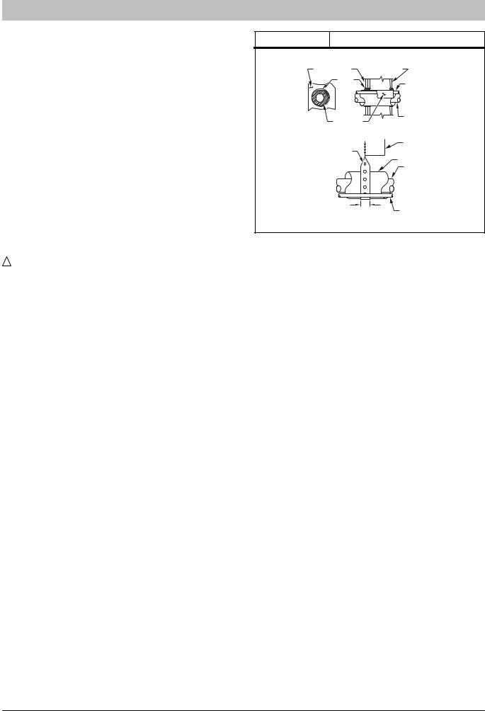
5.When passing refrigerant tubes through the wall, seal opening with RTV or other pliable silicon−based caulk. (See Fig. 1.)
6.Avoid direct tubing contact with water pipes, duct work, floor joists, wall studs, floors, and walls.
7.Do not suspend refrigerant tubing from joists and studs with a rigid wire or strap which comes in direct contact with tubing.(See Fig. 1.)
8.Ensure that tubing insulation is pliable and completely surrounds vapor tube.
9.When necessary, use hanger straps which are 1 in. (25.4 mm) wide and conform to shape of tubing insulation. (See Fig. 1.)
10.Isolate hanger straps from insulation by using metal sleeves bent to conform to shape of insulation.
|
|
R−410A Split System Heat Pumps |
Figure 1 |
Connecting Tube Installation |
|
|
NOTE: Avoid contact between tubing and structure |
|
|
OUTDOOR WALL |
INDOOR WALL |
|
CAULK |
LIQUID TUBE |
|
|
|
|
|
VAPOR TUBE |
|
INSULATION |
|
|
THROUGH THE WALL |
|
|
|
JOIST |
|
HANGER STRAP |
|
|
(AROUND VAPOR |
INSULATION |
|
TUBE ONLY) |
|
|
|
|
|
|
VAPOR TUBE |
|
1″ (25.4 mm)MIN. |
|
|
|
LIQUID TUBE |
|
SUSPENSION |
|
When outdoor unit is connected to factory−approved indoor unit, outdoor unit contains system refrigerant charge for operation with AHRI rated indoor unit when connected by 15 ft. (4.57 m) of field−supplied or factory accessory tubing. For proper unit operation, check refrigerant charge using charging information located on control box cover and/or in the Check Charge section of this instruction.
IMPORTANT: Maximum liquid−line size is 3/8−in. OD for all residential applications including long line.
IMPORTANT: Always install the factory−supplied liquid−line filter drier. Obtain replacement filter driers from your distributor or branch.
INSTALLATION
Check Equipment and Job Site
Unpack Unit
Move to final location. Remove carton taking care not to damage unit.
Inspect Equipment
File claim with shipping company prior to installation if shipment is damaged or incomplete. Locate unit rating plate on unit corner panel. It contains information needed to properly install unit. Check rating plate to be sure unit matches job specifications.
Install on a Solid, Level Mounting Pad
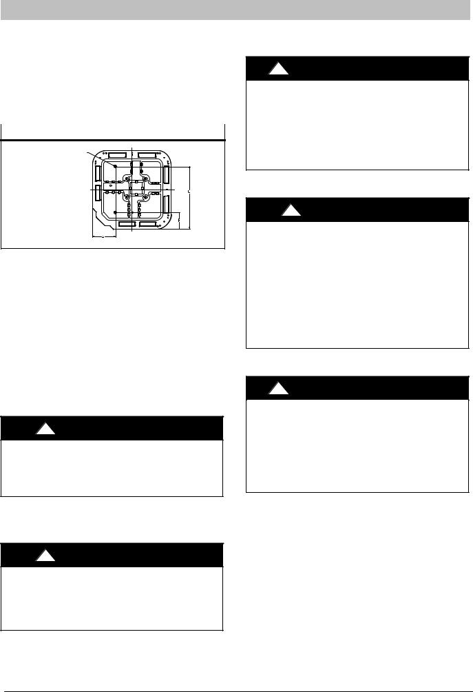
If conditions or local codes require the unit be attached to pad, tie down bolts should be used and fastened through knockouts provided in unit base pan. Refer to unit mounting pattern in Fig. 2 to determine base pan size and knockout hole location.
For hurricane tie downs − contact your local distributor for details and PE (Professional Certification), if required by local authorities.
On rooftop applications, mount on level platform or frame. Place unit above a load−bearing wall and isolate unit and tubing set from structure. Arrange supporting members to adequately support unit and minimize transmission of vibration to building. Consult local codes governing rooftop applications.
Roof mounted units exposed to winds may require wind baffles. Consult the Low−Ambient pressure switch installation instructions for wind baffle construction.
NOTE: Unit must be level to within ±2_ (±3/8 in./ft..) per compressor manufacturer specifications.
2 |
428 01 1701 00 |
INSTALLATION INSTRUCTIONS
Clearance Requirements
When installing, allow sufficient space for airflow clearance, wiring, refrigerant piping, and service. Allow 24 in. (610 mm) clearance to service end of unit and 48 in. (1219.2 mm) above unit. For proper airflow, a 6 in. (152.4 mm) clearance on one side of unit and 12 in. (304.8 mm) on all remaining sides must be maintained. Maintain a distance of 24 in. (609.6 mm) between units. Position so water, snow, or ice from roof or eaves cannot fall directly on unit.
Figure 2 |
Tie Down Knockouts |
|
|
3/8-in. (9.53 mm) Dia. |
Tiedown Knockouts in |
Basepan(2) Places |
View From Top
UNIT BASE PAN |
TIEDOWN KNOCKOUT LOCATIONS in. (mm) |
||
Dimension |
A |
B |
C |
35 X 35 |
9–1/8 (231.8) |
6–9/16 (166.7) |
28–7/16 (722.3) |
On rooftop applications, locate unit at least 6 in. (152.4 mm) above roof surface.
Operating Ambient
The minimum outdoor operating ambient in cooling mode is 55°F (12.78_C), and the maximum outdoor operating ambient in cooling mode is 125°F (51.67_C). At line voltage of 208V (or below) and an outdoor ambient of 120°F (48.9°C) (and above), the compressor operates in low stage The maximum outdoor operating ambient in heating mode is 66° F (18.89 _C). This unit is not approved for low ambient cooling applications.
Elevate Unit
!CAUTION
UNIT DAMAGE HAZARD
Failure to follow this caution may result in equipment damage or improper operation.
Unit must be kept free of an accumulation of water and/or ice in the basepan.
Elevate unit per local climate and code requirements to provide clearance above estimated snowfall level and ensure adequate drainage of unit. If using accessory support feet, use installation instructions from kit for installation.
!CAUTION
UNIT DAMAGE HAZARD
Failure to follow this caution may result in equipment damage or improper operation.
To prevent damage to the unit, ensure that it is located with the supports such that the unit is stable in all circumstances including adverse conditions.
R−410A Split System Heat Pumps
Make Piping Connections
!WARNING
PERSONAL INJURY AND ENVIRONMENTAL HAZARD
Failure to follow this warning could result in personal injury or death.
Relieve pressure and recover all refrigerant before system repair or final unit disposal.
Use all service ports and open all flow−control devices, including solenoid valves.
!CAUTION
UNIT DAMAGE HAZARD
Failure to follow this caution may result in equipment damage or improper operation.
Do not leave system open to atmosphere any longer than minimum required for installation. POE oil in compressor is extremely susceptible to moisture absorption. Always keep ends of tubing sealed during installation.
If ANY refrigerant tubing is buried, provide a 6 in. (152.4 mm) vertical rise at service valve. Refrigerant tubing lengths up to 36 in. (914.4 mm) may be buried without further special consideration. Do not bury lines more than 36 in. (914.4 mm).
!WARNING
PERSONAL DAMAGE HAZARD
Failure to follow this warning may result in equipment damage or improper operation.
To prevent damage to unit or service valves, observe the following:
SUse a brazing shield.
SWrap service valves with wet cloth or use a heat sink material.
Outdoor units may be connected to indoor section using accessory tubing package or field−supplied refrigerant grade tubing of correct size and condition. For tubing requirements beyond 80 ft/24.38 m, substantial capacity and performance losses can occur. Following the recommendations in the Long Line Applications Guideline will reduce these losses. Refer to Table 1 for accessory requirements. Refer to Table 2 for field tubing diameters.
If refrigerant tubes or indoor coil are exposed to atmosphere, they must be evacuated to 500 microns to eliminate contamination and moisture in the system.
428 01 1701 00 |
3 |
INSTALLATION INSTRUCTIONS |
R−410A Split System Heat Pumps |
|
|
Table 1 − Accessory Usage
|
|
REQUIRED FOR SEA COAST |
|
REQUIRED FOR LONG LINE |
APPLICATIONS |
Accessory |
APPLICATIONS* (Over 80 ft. / 24.38 m) |
(within 2 miles/3.22 km) |
Accumulator |
Yes, Standard |
Standard |
Compressor Start Assist Capacitor and Relay |
Yes |
No |
Crankcase Heater |
Yes, Standard |
No |
Liquid Line Solenoid Valve |
See Long Line Applications Guideline |
No |
Support Feet |
No |
Recommended |
* For tubing line sets between 80 and 200 ft. (24.38 and 60.96 m) and/or 20 ft. (6.09 m) vertical differential, refer to Long Line Applications Guideline.
Table 2 − Refrigerant Connections and Recommended Liquid and Vapor Tube Diameters (In.)
|
|
|
|
RATED VAPOR |
|
|
|
LIQUID |
|
up to 80 ft. (24.38 m)* |
|
UNIT SIZE |
Connection Diameter |
Tube Diameter |
Connection Diameter |
Rated Tube Diameter |
|
624, |
924 |
3/8 |
3/8 |
3/4 |
3/4 |
636, 936 |
3/8 |
3/8 |
7/8 |
7/8 |
|
648, 948, 660, 960 |
3/8 |
3/8 |
7/8 |
1−1/8 |
|
* Units are rated with 25 ft. (7.6 m) of lineset. See Specification sheet for performance data when using different size and length linesets.
Notes:
1.Do not apply capillary tube or fixed orifice indoor coils to these units.
2.For Tubing Set lengths between 80 and 200 ft. (24.38 and 60.96 m) horizontal or 35 ft. (10.7 m) vertical differential 250 ft. (76.2 m) Total Equivalent Length), refer to the Long Line Applications Guideline.
ISO 9001:2000
REGISTERED
Use of the AHRI Certified TM Mark indicates a manufacturer’s participation in the program For verification
of certification for individual products, go to www.ahridirectory.org.
This product has been designed and manufactured to meet Energy Star→ criteria for energy efficiency when matched with appropriate coil components. However, proper refrigerant charge and proper air flow are critical to achieve rated capacity and efficiency. Installation of this product should follow all manufacturing refrigerant charging and air flow instructions. Failure to confirm proper charge and
air flow may reduce energy efficiency and shorten
equipment life.
4 |
428 01 1701 00 |

INSTALLATION INSTRUCTIONS
Outdoor Unit Connected to Factory Approved Indoor Unit
These outdoor units are carefully evaluated and listed with specific indoor coils for proper system performance.
Install Adapter Tube
1.Remove plastic retainer holding outdoor piston in liquid service valve.
2.Check outdoor piston size with matching number listed on unit rating plate.
3.Locate plastic bag taped to unit containing adapter tube.
4.Remove Teflon→ seal from bag and install on open end of liquid service valve. (See Fig. 3.)
5.Remove adapter tube from bag and connect threaded nut to liquid service valve. Tighten nut finger−tight and then with wrench an additional 1/2 turn (15 ft−lb). DO
NOT OVER TIGHTEN!
Figure 3 |
Liquid Service Valve |
Install Liquid Line Filter Drier Indoor
Refer to Fig. 4 and install filter drier as follows:
1.Braze 5 in. (127 mm) liquid tube to the indoor coil.
2.Wrap filter drier with damp cloth.
3.Braze filter drier to 5 in. (127 mm) liquid tube from step 1.
4.Connect and braze liquid refrigerant tube to the filter drier.
Figure 4 |
|
|
Liquid Line Filter Drier |
||
|
|
|
|
|
|
|
|
|
|
|
|
|
|
|
|
|
|
|
|
|
|
|
|
|
|
|
|
|
|
|
|
|
|
|
|
|
|
|
|
|
|
|
|
|
|
|
|
|
|
|
|
|
|
|
|
|
|
|
|
|
|
|
|
|
|
Refrigerant Tubing and Sweat Connections
Use refrigerant grade tubing. Service valves are closed from factory and ready for brazing. After wrapping service valves with a wet cloth, braze sweat connections using industry accepted methods and materials. Consult local code requirements. Refrigerant tubing and indoor coil are now ready for leak testing . This check should include all field and factory joints.
R−410A Split System Heat Pumps
!CAUTION
UNIT DAMAGE HAZARD
Failure to follow this caution may result in equipment damage or improper operation.
Service valves must be wrapped in a heat−sinking material such as a wet cloth while brazing.
!CAUTION
UNIT DAMAGE HAZARD
Failure to follow this caution may result in equipment damage or improper operation.
Installation of filter drier in liquid line is required.
Evacuate Refrigerant Tubing and Indoor Coil
!CAUTION
UNIT DAMAGE HAZARD
Failure to follow this caution may result in equipment damage or improper operation.
Never use the system compressor as a vacuum pump.
Refrigerant tubes and indoor coil should be evacuated using the recommended deep vacuum method of 500 microns. An alternate triple evacuation method may be used.
IMPORTANT: Always break a vacuum with dry nitrogen.
Deep Vacuum Method
The deep vacuum method requires a vacuum pump capable of pulling a vacuum of 500 microns and a vacuum gage capable of accurately measuring this vacuum depth. The deep vacuum method is the most positive way of assuring a system is free of air and liquid water. (See Fig.5)
Figure 5 |
|
|
|
Deep Vacuum Graph |
|||
5000 |
|
|
|
|
|
|
|
4500 |
|
|
|
|
|
|
|
4000 |
|
|
|
|
|
LEAK IN |
|
3500 |
|
|
|
|
|
||
|
|
|
|
|
SYSTEM |
||
3000 |
|
|
|
|
|
||
|
|
|
|
|
|
|
|
2500 |
|
|
|
|
|
|
|
MICRONS2000 |
|
|
|
|
|
VACUUM TIGHT |
|
1500 |
|
|
|
|
|
||
|
|
|
|
|
TOO WET |
||
1000 |
|
|
|
|
|
||
|
|
|
|
|
TIGHT |
||
500 |
|
|
|
|
|
||
|
|
|
|
|
DRY SYSTEM |
||
|
|
|
|
|
|
||
0 |
1 |
2 |
3 |
4 |
5 |
6 |
7 |
|
|
|
MINUTES |
|
|
|
|
Triple Evacuation Method
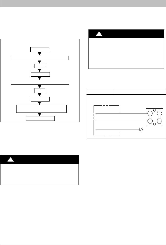
The triple evacuation method should only be used when system does not contain any water in liquid form and vacuum pump is only capable of pulling down to 28 inches of mercury (711mm Hg). Refer to Fig. 6 and proceed is as follows:
1.Pull system down to 28 inches of mercury (711mm Hg) and allow pump to continue operating for an additional 15 minutes.
2.Close manifold valves or valve at vacuum pump and shut off vacuum pump.
3.Connect a nitrogen cylinder and regulator to system and fill with nitrogen until system pressure is 2 psig.
428 01 1701 00 |
5 |
INSTALLATION INSTRUCTIONS
4.Close nitrogen valve and allow system to stand for 1 hour. During this time, dry nitrogen will diffuse throughout the system absorbing moisture.
5.Repeat this procedure as indicated in Figure 6.
6.After the final evacuate sequence, confirm there are no leaks in the system. If a leak is found, repeat the entire process after repair is made.
Figure 6 |
Triple Evacuation Sequence |
|
|
EVACUATE
BREAK VACUUM WITH DRY NITROGEN
WAIT
EVACUATE
BREAK VACUUM WITH DRY NITROGEN
WAIT
EVACUATE
CHECK FOR TIGHT, DRY SYSTEM (IF IT HOLDS DEEP VACUUM
CHARGE SYSTEM
Final Tubing Check
IMPORTANT: Check to be certain factory tubing on both indoor and outdoor unit has not shifted during shipment. Ensure tubes are not rubbing against each other or any sheet metal. Pay close attention to feeder tubes, making sure wire ties on feeder tubes are secure and tight.
Make Electrical Connections
!WARNING
ELECTRICAL SHOCK HAZARD
Failure to follow this warning could result in personal injury or death.
Do not supply power to unit with compressor terminal box cover removed.
Be sure field wiring complies with local and national fire, safety, and electrical codes, and voltage to system is within limits shown on unit rating plate. Contact local power company for correction of improper voltage. See unit rating plate for recommended circuit protection device.
NOTE: Operation of unit on improper line voltage constitutes abuse and could affect unit reliability. See unit rating plate. Do not install unit in system where voltage may fluctuate above or below permissible limits.
NOTE: Use copper wire only between disconnect switch and unit.
NOTE: Install branch circuit disconnect of adequate size per NEC to handle unit starting current. Locate disconnect within sight from and readily accessible from unit, per Section 440−14 of NEC.
R−410A Split System Heat Pumps
Route Ground and Power Wires
Remove access panel to gain access to unit wiring. Extend wires from disconnect through power wiring hole provided and into unit control box.
!WARNING
ELECTRICAL SHOCK HAZARD
Failure to follow this warning could result in personal injury or death.
The unit cabinet must have an uninterrupted or unbroken ground to minimize personal injury if an electrical fault should occur. The ground may consist of electrical wire or metal conduit when installed in accordance with existing electrical codes.
Connect Ground and Power Wires
Connect ground wire to ground connection in control box for safety. Connect power wiring to contactor as shown in Fig. 7.
Figure 7 |
Line Power Connections |
DISCONNECT |
|
PER N. E. C. AND/OR |
|
LOCAL CODES |
|
|
CONTACTOR |
FIELD POWER |
|
WIRING |
|
FIELD GROUND |
|
WIRING |
GROUND |
|
|
|
LUG |
Connect Control Wiring
This unit is capable of communication with an Observer Wall Control, or will operate using standard 24v 2−stage thermostat. Route 24v control wires through control wiring grommet and connect leads to control board. When an Observer Wall Control is available, connect DX+ and DX− connections only. If a 2−stage thermostat is used, connect to the Y1, Y2, W1, and O connections. Refer to the wiring label for further clarification.
Use No. 18 AWG color−coded, insulated (35_C minimum) wire. If thermostat is located more than 100 ft. (30.48 m) from unit, as measured along the control voltage wires, use No. 16 AWG color−coded, insulated wire to avoid excessive voltage drop.
All wiring must be NEC Class 1 and must be separated from incoming power leads.
Use furnace transformer, fan coil transformer, or accessory transformer for control power, 24−v/40−va minimum.
NOTE: Use of available 24−v accessories may exceed the minimum 40−va power requirement. Determine total transformer load and increase the transformer capacity or split the load with an accessory transformer as required.
Final Wiring Check
IMPORTANT: Check factory wiring and field wire connections to ensure terminations are secured properly. Check wire routing to ensure wires are not in contact with tubing, sheet metal, etc.
6 |
428 01 1701 00 |
 Loading...