


F9MXT0401410A1
International Comfort Products F9MXT0401410A1, G9MXT0401410A1, F9MXT0601714A1, G9MXT0601714A1, F9MXT0801716A1 User Manual
...
440 03 4321 00 March. 2012
PARTS MANUAL
Gas Furnace
F9MXT, G9MXT
DANGER, WARNING, CAUTION, and
NOTE
The signal words DANGER, WARNING, CAUTION,
and NOTE are used to identify levels of hazard
seriousness. The signal word DANGER is only used on
product labels to signify an immediate hazard. The
signal words WARNING, CAUTION, and NOTE will be
used on product labels and throughout this manual and
other manuals that may apply to the product.
DANGER − Immediate hazards which will result in
severe personal injury or death.
WARNING − Hazards or unsafe practices which could
result in severe personal injury or death.
CAUTION − Hazards or unsafe practices which may
result in minor personal injury or product or property
damage.
NOTE − Used to highlight suggestions which will result
in enhanced installation, reliability, or operation.
Signal Words in Manuals
The signal word WARNING is used throughout this
manual in the following manner:
The signal word CAUTION is used throughout this
manual in the following manner:
Signal Words on Product Labeling
Signal words are used in combination with colors
and/or pictures on product labels.
WARNING
Safety Labeling and Signal Words
!
!
CAUTION
WARNING
TABLE OF CONTENTS
Model Number Identification 2.....................
Parts Diagram 3.................................
Parts 9.........................................
MODELS
F9MXT0401410A1 G9MXT0401410A1.............
F9MXT0601714A1 G9MXT0601714A1.............
F9MXT0801716A1 G9MXT0801716A1.............
F9MXT0802120A1 G9MXT0802120A1.............
F9MXT1002116A1 G9MXT1002116A1..............
F9MXT1002120A1 G9MXT1002120A1.............
F9MXT1202422A1 G9MXT1202422A1.............
!
WARNING
ELECTRICAL SHOCK HAZARD
Failure to turn off electric power could result in
personal injury or death.
Before installing or servicing system, turn off
main power to the system. There may be more than
one disconnect switch, including accessory heat-
er(s).
PARTS MANUAL Gas Furnace: F9MXT, G9MXT
2 440 03 4321 00
MODEL NUMBER IDENTIFICATION GUIDE
DIGIT POSITION 1 2 3 4 5 6,7,8 9,10 11,12 13 14
(F/G) = Mainline * 9 M X T 060 17 14 A 1
N = Entry
9 = 90+% AFUE EFFICIENCY
M = Multiposition POSITION
A = Modulating ECM Variable Speed Blower
V = ECM Variable Speed
X = ECM Blower
S = Single−stage
T = Two−stage TYPE
C = Communicating
E = Extra AFUE Efficiency
T = Two−Stage FEATURE
040 = 40,000 BTU/hr
060 = 60,000 BTU/hr
080 = 80,000 BTU/hr
100 = 100,000 BTU/hr
120 = 120,000 BTU/hr HEAT INPUT
14 = 14−3/16”
17 = 17−1/2”
21 = 21”
24 = 24−1/2” CABINET WIDTH
08 = 800 CFM
12 = 1200 CFM
14 = 1400 CFM
16 = 1600 CFM
20 = 2000 CFM
22 = 2200 CFM NOMINAL MAXIMUM COOLING AIRFLOW @ .5 IN. W.C.
SALES (MAJOR) REVISION DIGIT
ENGINEERING (MINOR) REVISION DIGIT
ECM-Electronically Commutated Motor
ACCESSORIES PART NUMBER IDENTIFICATION GUIDE
DIGIT POSITION
1 2 3 4 5, 6, 7 8, 9 10, 11
N A H A 001 01 DH
N = Non−Branded BRANDING
A = Accessory PRODUCT GROUP
H = Heating KIT USAGE
A = Original
B = 2nd Generation MAJOR SERIES
Product Identifier Number
Package Quantity
Type of Kit (Example: DH = Draft Hood − Chimney Adapter)

PARTS MANUAL Gas Furnace: F9MXT, G9MXT
440 03 4321 00 3
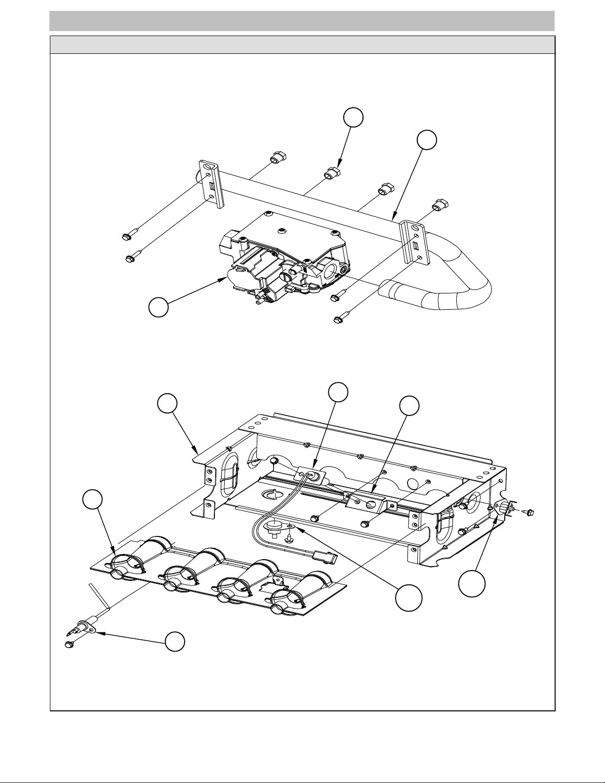
PARTS DIAGRAM
9MAC−1
NOTE: This illustration is for
reference only. Your unit may
differ in appearance or may not
include all components shown.
8
7
J
B
C
5
VV
3
G
E
31
KK
13
30
X
23
MM
M
ZZ
Z
PP
D
A
PARTS MANUAL Gas Furnace: F9MXT, G9MXT
4 440 03 4321 00
PARTS DIAGRAM
9MAC−2
NOTE: This illustration is for
reference only. Your unit may
differ in appearance or may not
include all components shown.
14
P
15
10
11
T
12
TT
16B
16A
 Loading...