


International Comfort Products G9MAE0601714A, G9MAE0602120A, G9MAE0801714A, G9MAE0802120A, G9MAE1002122A TECHNICAL MANUAL
...SERVICE AND TECHNICAL
SUPPORT MANUAL
Modulating, Variable Speed Blower Motor 35” Tall, High Efficiency Condensing Gas Furnace
(F/G)9MAE
Save this manual for future reference.
Safety Labeling and Signal Words
DANGER, WARNING, CAUTION, and NOTE
The signal words DANGER, WARNING, CAUTION, and NOTE are used to identify levels of hazard seriousness. The signal word DANGER is only used on product labels to signify an immediate hazard. The signal words WARNING, CAUTION, and NOTE will be used on product labels and throughout this manual and other manual that may apply to the product.
DANGER − Immediate hazards which will result in severe personal injury or death.
WARNING − Hazards or unsafe practices which could result in severe personal injury or death.
CAUTION − Hazards or unsafe practices which may result in minor personal injury or product or property damage.
NOTE − Used to highlight suggestions which will result in enhanced installation, reliability, or operation.
Signal Words in Manuals
The signal word WARNING is used throughout this manual in the following manner:
! WARNING
The signal word CAUTION is used throughout this manual in the following manner:
! CAUTION
Signal Words on Product Labeling
Signal words are used in combination with colors and/or pictures or product labels.
Safety−alert symbol
When you see this symbol on the unit and in instructions or manuals, be alert to the potential for personal injury.
TABLE OF CONTENTS |
|
START−UP, ADJUSTMENT, AND SAFETY CHECK . . . . . . . . . . . |
4 |
SELECT SETUP SWITCH POSITIONS . . . . . . . . . . . . . . . . . . . . . |
4 |
PRIME CONDENSATE TRAP WITH WATER . . . . . . . . . . . . . . . . . |
4 |
PURGE GAS LINES . . . . . . . . . . . . . . . . . . . . . . . . . . . . . . . . . . . . . . |
5 |
ADJUSTMENTS . . . . . . . . . . . . . . . . . . . . . . . . . . . . . . . . . . . . . . . . . |
5 |
ADJUST TEMPERATURE RISE . . . . . . . . . . . . . . . . . . . . . . . . . . . . |
8 |
ADJUST BLOWER OFF DELAY (HEAT MODE) . . . . . . . . . . . . . . |
9 |
ADJUST COOLING AIRFLOW . . . . . . . . . . . . . . . . . . . . . . . . . . . . . |
9 |
ADJUST CONTINUOUS FAN AIRFLOW . . . . . . . . . . . . . . . . . . . . |
9 |
ADJUST THERMOSTAT HEAT ANTICIPATOR . . . . . . . . . . . . . . . |
11 |
CHECK SAFETY CONTROLS . . . . . . . . . . . . . . . . . . . . . . . . . . . . . |
12 |
CHECKLIST . . . . . . . . . . . . . . . . . . . . . . . . . . . . . . . . . . . . . . . . . . . . . |
12 |
COOLING AND HEATING AIR DELIVERY - CFM . . . . . . . . . . . . . |
17 |
SERVICE AND MAINTENANCE PROCEDURES . . . . . . . . . . . . . |
21 |
ELECTRICAL CONTROLS AND WIRING . . . . . . . . . . . . . . . . . . . |
21 |
CLEANING AND/OR REPLACING AIR FILTER . . . . . . . . . . . . . . |
23 |
CLEANING BURNERS AND FLAME SENSOR . . . . . . . . . . . . . . . |
25 |
SERVICING HOT SURFACE IGNITER . . . . . . . . . . . . . . . . . . . . . . |
26 |
FLUSHING COLLECTOR BOX AND DRAINAGE SYSTEM . . . . |
27 |
CLEANING CONDENSATE DRAIN AND TRAP . . . . . . . . . . . . . . |
27 |
WINTERIZATION . . . . . . . . . . . . . . . . . . . . . . . . . . . . . . . . . . . . . . . . |
28 |
SERVICE LABEL . . . . . . . . . . . . . . . . . . . . . . . . . . . . . . . . . . . . . . . . . |
29 |
TROUBLESHOOTING CHART − FLOW CHART . . . . . . . . . . . . . |
31 |
TROUBLESHOOTING GUIDE − FLOW CHART . . . . . . . . . . . . . . |
32 |
SEQUENCE OF OPERATION . . . . . . . . . . . . . . . . . . . . . . . . . . . . . |
34 |
PARTS REPLACEMENT INFORMATION GUIDE . . . . . . . . . . . . . |
38 |
PRODUCT NOMENCLATURE . . . . . . . . . . . . . . . . . . . . . . . . . . . . . |
39 |
MODELS
(F/G)9MAE0601714A
(F/G)9MAE0602120A
(F/G)9MAE0801714A
(F/G)9MAE0802120A
(F/G)9MAE1002122A
(F/G)9MAE1202422A
Use of the AHRI Certified TM Mark indicates a manufacturer’s participation in the program. For verification of certification for individual products, go to www.ahridirectory.org .
Printed in U.S.A.
440 04 4700 00 Aug. 2012
SAFETY CONSIDERATIONS
Improper installation, adjustment, alteration, service, maintenance, or use can cause explosion, fire, electrical shock, or other conditions which may cause death, personal injury, or property damage. Consult a qualified installer, service agency, or your distributor or branch for information or assistance. The qualified installer or agency must use factory−authorized kits or accessories when modifying this product. Refer to the individual instructions packaged with the kits or accessories when installing.
Follow all safety codes. Wear safety glasses, protective clothing, and work gloves. Use quenching cloth for brazing operations. Have fire extinguisher available. Read these instructions thoroughly and follow all warnings or cautions included in literature and attached to the unit. Consult local building codes, the current editions of the National Fuel Gas Code (NFCG) NFPA 54/ANSI Z223.1, and the National Electrical Code (NEC) NFPA 70.
In Canada refer to the current editions of the National standards of Canada CAN/CSA−B149.1 and .2 Natural Gas and Propane Installation Codes, and Canadian Electrical Code CSA C22.1.
Recognize safety information. This is the safety−alert symbol
 . When you see this symbol on the unit and in instructions or manuals, be alert to the potential for personal injury. Understand these signal words; DANGER, WARNING, and CAUTION. These words are used with the safety−alert symbol. DANGER identifies the most serious hazards which will result in severe personal injury or death. WARNING signifies hazards which could result in personal injury or death. CAUTION is used to identify unsafe practices which may result in minor personal injury or product and property damage. NOTE is used to highlight suggestions which will result in enhanced installation, reliability, or operation.
! WARNING
PERSONAL INJURY, AND/OR PROPERTY DAMAGE HAZARD
Failure to carefully read and follow this warning could result in equipment malfunction, property damage, personal injury and/or death.
Installation or repairs made by unqualified persons could result in equipment malfunction, property damage, personal injury and/or death.
The information contained in this manual is intended for use by a qualified service technician familiar with safety procedures and equipped with proper tools and test instruments.
Installation must conform with local building codes and with the Natural Fuel Gas Code (NFCG) NFPA 54/ANSI Z223.1, and National standards of Canada CAN/CSA−B149.1 and .2 Natural Gas and Propane Installation Codes.
!WARNING
ELECTRICAL SHOCK HAZARD
Failure to follow this warning could cause personal injury or death.
Before performing service or maintenance operations on unit, always turn off main power switch to unit and install lockout tag. Unit may have more than one power switch.
!WARNING
CARBON MONOXIDE POISONING AND FIRE HAZARD
Failure to follow safety warnings could result in personal injury, death, and/or property damage.
This furnace is not designed for use in mobile homes, trailers or recreational vehicles.
! CAUTION
CUT HAZARD
Failure to follow this caution may result in damage personal injury.
Sheet metal parts may have sharp edges or burrs. Use care and wear appropriate protective clothing, safety glasses and gloves when handling parts and servicing furnaces.
2 |
Specifications are subject to change without notice. |
440 04 4700 00 |
SERVICE AND TECHNICAL SUPPORT MANUAL |
Gas Furnace: (F/G)9MAE |
START−UP CHECK SHEET
For Variable Speed Models (F/G)9MAE
(This sheet is optional. Keep for future reference.)
Date of Start−Up:
Dealer Name:
Address:
City, State(Province), Zip or Postal Code:
Phone:
Owner Name:
Address:
City, State(Province), Zip or Postal Code:
Model Number:
Serial Number:
Setup Checks
Check the box when task is complete.
All Electrical Connections Tight?
Have hoses been relocated for furnace U/D/H application?
Condensate Drain Connected?
Condensate Drain Trapped?
Manual Gas Shut−off Upstream of Furnace/Drip Leg
Gas Valve turned ON?
Type of Gas: |
Natural: |
|
|
Propane: |
|
|
|
|
|
|
|
|
|
||||
Filter Type and Size: |
|
|
|
|
|
|
||
Shade in Final Furnace Settings Below:
Heating Check
Measured Line Pressure During High Heat:
Measured Manifold Pressure: |
Max Heat |
|
Min Heat |
Temperature of Supply Air: |
Max Heat |
|
Min Heat |
Temperature of Return Air:
Temperature Rise (Supply − Return): Max Heat
Min Heat
In Rise Range (see furnace rating plate)? Static Pressure (Ducts) High Heat: Supply
Return
Optional Check: CO?
CO2?
Cooling Check
Temperature of Supply Air:
Temperature of Return Air:
Temperature Difference:
Static Pressure (Ducts) Cooling: Supply
Return
Dealer Comments:
Calculated Input (BTU) Rate: (See Checks and
Adjustments Section).
440 04 4700 00 |
Specifications subject to change without notice. |
3 |
|
|
SERVICE AND TECHNICAL SUPPORT MANUAL
START−UP, ADJUSTMENT, AND SAFETY CHECK
General
1.Furnace must have a 115-v power supply properly connected and grounded.
NOTE: Proper polarity must be maintained for 115-v wiring. Control status indicator light flashes code 10 and furnace does not operate if polarity is incorrect or if the furnace is not grounded.
2.Thermostat wire connections at terminals R, W/W1, G, Y/Y2, etc. must be made at 24-v terminal block on furnace control. See communicating wall control instructions for proper wiring of communicating controls.
3.Natural gas service pressure must not exceed 0.5 psig (14in. w.c., 350 Pa), but must be no less than 0.16 psig (4.5-in. w.c., 1125 Pa).
4. Blower door must be in place to complete 115-v electrical circuit and supply power to furnace.
!CAUTION
UNIT OPERATION HAZARD
Failure to follow this caution may result in intermittent unit operation or performance dissatisfaction.
These furnaces are equipped with a manual reset limit switch in burner assembly. This switch opens and shuts off power to the gas valve if an overheat condition (flame rollout) occurs in the burner assembly/enclosure. Correct inadequate combustion-air supply, improper gas pressure setting, improper burner or gas orifice positioning, or improper venting condition before resetting switch. DO NOT jumper this switch.
Before operating furnace, check flame rollout manual reset switch for continuity. If necessary, press button to reset switch.
EAC-1 terminal is energized whenever blower operates. HUM terminal is only energized when blower is energized in heating.
Select Setup Switch Positions
There are four sets of setup switches on the furnace control board. These switches configure the furnace for correct application requirement. They also select the airflow settings for Air Conditioning and Continuous Fan airflows.
The Setup Switch locations are shown and described on
Figure 3, Figure 4, Table 3 and Table 6. The set up switches are also shown on the unit wiring label.
Setup Switches (SW1)
The furnace control has eight setup switches that may be set to meet the application requirements. Refer to Figure 4 and Adjustments section for set up switch configurations.
To set these setup switches for the appropriate requirement:
1.Remove blower door.
2.Locate setup switches on furnace control.
3.Configure the set-up switches as necessary for the application.
4.Replace blower door.
NOTE: If a bypass humidifier is used, setup switch SW1-3 (Min/Int Rise Adjust) should be in ON position. This compensates for the increased temperature in return air resulting from bypass.
NOTE: If modulating dampers are used, blower motor automatically compensates for modulating dampers.
Air Conditioning (A/C) Setup Switches (SW2)
The air conditioning setup switches are used to match furnace airflow to required cooling airflow or high stage cooling airflow
Gas Furnace: (F/G)9MAE
when a two−stage outdoor unit is used. Refer to Figure 4 and the Adjustments section for set up switch configurations.
To set the desired cooling airflow:
1.Remove blower door.
2.Locate A/C setup switches on furnace control.
3.Determine air conditioning tonnage used.
4.Configure the switches for the required cooling airflow. NOTE: Incorrect airflow caused by improper A/C switch setup may cause condensate blow−off or a frozen indoor coil in the
cooling mode.
5. Replace blower door.
Continuous Fan (CF) Setup Switches (SW3)
The CF setup switches are used to select desired airflow when thermostat is in continuous fan mode or to select low-cooling airflow for two-speed cooling units. Refer to Figure 4 and the Adjustments section for set up switch configurations.
1.Remove blower door.
2.Locate CF setup switches on furnace control.
3.Determine desired continuous fan airflow or low-cooling airflow.
4.Configure the switches for the required continuous fan or low−cooling airflow.
5.Replace blower door.
Additional Setup Switches (SW4)
The furnace control has three additional setup switches labeled SW4.
Setup switch SW4-2 can be used to lock the furnace into intermediate heat. When setup switch SW4-2 is ON it will over ride setup switch SW1-2 if it is ON. SW4−3 is used to adjust airflow. Refer to Figure 4 and the Adjustments section for set up switch configurations.
1.Remove blower door.
2.Locate setup switch SW4 on furnace control.
3.Configure the switches for the required heat stages air flow if necessary.
4.Replace blower door.
Prime Condensate Trap with Water
!WARNING
FIRE OR EXPLOSION HAZARD
Failure to follow these warnings could result in personal injury or death.
Failure to use a properly configured trap or NOT water-priming trap before operating furnace may allow positive pressure vent gases to enter the structure through drain tube. Vent gases contain carbon monoxide which is tasteless and odorless.
!CAUTION
UNIT OPERATION HAZARD
Failure to follow this caution may result in intermittent unit operation or performance satisfaction.
Condensate trap must be PRIMED or proper draining may not occur. The condensate trap has two internal chambers which can ONLY be primed by pouring water into the inducer drain side of condensate trap.
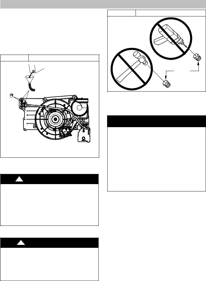
1.Remove upper and middle collector box drain plugs opposite of the condensate trap. (See Figure 1)
2.Connect field-supplied 5/8-in. (16 mm) ID tube with attached funnel (see Figure 1) to upper collector box drain connection.
4 |
Specifications subject to change without notice. |
440 04 4700 00 |
|
|
SERVICE AND TECHNICAL SUPPORT MANUAL
3.Pour one quart (liter) of water into funnel/tube. Water should run through collector box, overfill condensate trap, and flow into open field drain.
4.Remove funnel; replace collector box drain plug.
5.Connect field-supplied 5/8-in. (16 mm) ID tube to middle collector box drain port.
6.Pour one quart (liter) of water into funnel/tube. Water should run through collector box, overfill condensate trap, and flow into open field drain.
7.Remove funnel and tube from collector box and replace collector box drain plug.
Figure 1 Priming Condensate Drain
Representative drawing only, some models may vary in appearance.
L11F065
Purge Gas Lines
If not previously done, purge the lines after all connections have been made and check for leaks.
!WARNING
FIRE OR EXPLOSION HAZARD
Failure to follow this warning could result in personal injury, death, and/or property damage.
Never purge a gas line into a combustion chamber. Never test for gas leaks with an open flame. Use a commercially available soap solution made specifically for the detection of leaks to check all connections. A fire or explosion may result causing property damage, personal injury or loss of life.
Adjustments
!CAUTION
FURNACE DAMAGE HAZARD
Failure to follow this caution could result in reduced furnace life.
DO NOT push or force gas valve adjusting screw. This can result in damage to the adjustment screw resulting in incorrect manifold pressure, which can result in a no heat situation or shorten the life of the heat exchangers.
Gas Furnace: (F/G)9MAE
Figure 2 |
Orifice Hole |
|
BURNER |
|
ORIFICE |
|
A93059 |
For proper operation and long term reliability, the Furnace input rate must be within +/− 2 percent of input rate on furnace rating plate, or as adjusted for altitude.
The gas input rate on rating plate is for installations at altitudes up to 2000 ft. (610 M).
NOTICE
The NATURAL GAS manifold pressure adjustments in Table 4 and Table 5 compensate for BOTH altitude AND gas heating value. DO NOT apply an additional de−rate factor to the pressures shown in Table 4 or Table 5. The values in these Tables are NOT referenced to sea level; they are AS−MEASURED AT ALTITUDE.
The heating content of natural gas at altitude may already provide for a reduction in capacity or the furnace. Be sure to obtain the expected in−season gas heating value of the gas from the gas supplier BEFORE making any adjustments for capacity or altitude. Refer to Table 4 or Table 5. No adjustments to the furnace may be necessary at altitude for certain gas heating values.
Refer to the instructions provided in the factory-specified LP/Propane conversion kit for instructions for setting gas manifold pressures for LP/Propane applications.
In the USA, the input rating for altitudes above 2000 ft. (610 M) must be reduced by 2 percent for each 1000 ft. (305 M) above sea level. Refer to Table 1. The natural gas manifold pressures in Table 4 and Table 5 adjust for BOTH altitude and natural gas heating value.
In Canada, the input rating must be reduced by 5 percent for altitudes of 2000 ft. (610 M) to 4500 ft. (1372 M) above sea level. The natural gas manifold pressures in Table 4 and Table 5 adjust for BOTH altitude and natural gas heating value.
NOTE: For Canadian altitudes of 200 to 4500 ft. (610 to 1372 M), use USA altitudes of 2001 to 3000 ft. (611 to 914 M) in
Table 4 and Table 5.
To adjust manifold pressure to obtain the proper input rate, first, determine if the furnace has the correct orifice installed. At higher altitudes or different gas heat contents, it may be necessary to change the factory orifice to a different orifice. Tables have been provided in the furnace Service and Technical Manual to match the required orifice to the manifold pressure to the heat content and specific gravity of the gas.
NOTE: There are two sets of manifold pressure tables. Use Table 4 for all models EXCEPT *9MAE0602120 Btuh model. Use Table 5 for only the *9MAE0602120 model.
440 04 4700 00 |
Specifications subject to change without notice. |
5 |
|
|
SERVICE AND TECHNICAL SUPPORT MANUAL
To do this:
1.Obtain average heat value (at installed altitude) from local gas supplier.
2.Obtain average specific gravity from local gas supplier.
3.Find installation altitude range for your installation in the manifold pressure tables. See Table 4 for the 20,000 Btuh Max−Heat/8,000/Btuh Min−Heat per burner models or Table 5 for model *9MAE0602120 only (20,200 Btuh Max−Heat/8,000 Btuh Min−Heat per burner).
4.Find closest natural gas heat value and specific gravity in Table 4 or Table 5 depending on furnace gas input rate.
5.Follow heat value and specific gravity lines to point of intersection to find orifice size and maximum and minimum manifold pressure settings for proper operation.
6.Check and verify burner orifice size in furnace. Never assume orifice size. NEVER ASSUME ORIFICE SIZE. ALWAYS CHECK AND VERIFY.
NOTICE
If orifice hole appears damaged or it is suspected to have been redrilled, check orifice hole with a numbered drill bit of correct size. Never redrill an orifice. A burr−free and squarely aligned orifice hole is essential for proper flame characteristics.
7.Replace orifice with correct size, if required by Table 4 or Table 5 depending on furnace gas input rate. Use only factory−supplied orifices. See EXAMPLE 1.
EXAMPLE 1:
(See Table 4)
0 - 2000 ft. (0 - 609.6M) altitude Heating value = 1050 Btu/cu ft. Specific gravity = 0.62 Therefore: Orifice No. 44
(Furnace is shipped with No. 44 orifices. In this example, all main burner orifices are the correct size and do not need to be changed to obtain proper input rate.)
Manifold pressure: 3.4-in. w.c. (847 Pa) for Maximum heat,
.55-in. w.c. (349 Pa) for Minimum heat
NOTE: To convert gas manifold Table pressures to Pascals, multiply the in.w.c. value by 249.1 Pa/in. w.c. (1 in. wc. = 249.1 Pa).
Table 1 |
Altitude Derate Multiplier for U.S.A. |
||
ALTITUDE |
PERCENT |
DERATE MULTIPLIER |
|
FT. (M) |
OF DERATE |
FACTOR* |
|
|
|
|
|
0–2000 |
0 |
1.00 |
|
(0−610) |
|||
|
|
||
|
|
|
|
2001–3000 |
4−6 |
0.95 |
|
(610−914) |
|||
|
|
||
|
|
|
|
3001–4000 |
6−8 |
0.93 |
|
(914−1219) |
|||
|
|
||
|
|
|
|
4001–5000 |
8−10 |
0.91 |
|
(1219−1524) |
|||
|
|
||
|
|
|
|
5001–6000 |
10−12 |
0.89 |
|
(1524−1829) |
|||
|
|
||
|
|
|
|
6001–7000 |
12−14 |
0.87 |
|
(1829−2134) |
|||
|
|
||
|
|
|
|
7001–8000 |
14−16 |
0.85 |
|
(2134−2438) |
|||
|
|
||
|
|
|
|
8001–9000 |
16−18 |
0.83 |
|
(2438−2743) |
|||
|
|
||
|
|
|
|
9001–10,000 |
18−20 |
0.81 |
|
(2743−3048) |
|||
|
|
||
|
|
|
|
* Derate multiplier factors are based on midpoint altitude for altitude range.
Gas Furnace: (F/G)9MAE
NOTE: For Canadian altitudes of 2000 to 4500 ft. (610 to
1372 M), use USA altitudes of 2001 to 3000 ft. (610 to 914 M).
Check Inlet Gas Pressure
The inlet gas pressure must be checked with the furnace operating in maximum heat. This is necessary to make sure the inlet gas pressure does not fall below the minimum pressure of 4.5−in. w.c. for natural gas. The maximum inlet gas pressure is 13.6−in. w.c. If the inlet pressure is too low, you will not be able to adjust the manifold pressure to obtain the proper input rate. To check the inlet gas pressure:
1.Make sure the gas supply is turned off to the furnace and at the electric switch on the gas valve.
2.Remove the 1/8 inch NPT plug from the inlet pressure tap on the gas valve.
3.Connect a manometer to the inlet pressure tap on gas valve.
4.Turn on furnace power supply.
5.Turn gas supply manual shutoff valve to ON position.
6.Turn furnace gas valve switch to ON position.
7.Jumper the R to W/W1 and W2 thermostat connections at the furnace control board.
8.When main burners ignite, confirm inlet gas pressure is Between 4.5−in. w.c. and 13.6−in. w.c.
9.Remove jumper across thermostat connections to terminate call for heat. Wait until the blower off delay is completed.
10.Turn furnace gas valve electric switch to OFF position.
11.Turn gas supply manual shutoff valve to OFF position.
12.Turn off furnace power supply.
13.Remove manometer from the inlet pressure tap of the gas valve.
!WARNING
FIRE HAZARD
Failure to follow this warning could result in personal injury, death, and/or property damage.
Re−install manifold pressure tap plug in gas valve to prevent gas leak.
14.Apply pipe dope sparingly to end of inlet gas pipe plug and re−install in the gas valve.
Adjust Manifold Pressure−Maximum Heat
The modulating furnace manifold pressure is set at two points. The first point is Maximum Heat.
The second point is Minimum Heat. Do not adjust Intermediate Heat manifold pressure. Intermediate Heat manifold pressure is checked as part of the temperature rise, but is not adjustable. Always adjust Maximum Heat first, then Minimum Heat.
NOTICE
DO NOT set maximum heat manifold pressure less than 3.2−in. w.c. (947 Pa) for natural gas. If required manifold pressure is outside this range, change main burner orifices to obtain manifold pressure in this range.
To adjust manifold pressure to obtain input rate for Maximum Heat:
1.Make sure the gas supply is turned off to the furnace and at the electric switch on the gas valve.
6 |
Specifications subject to change without notice. |
440 04 4700 00 |
|
|
SERVICE AND TECHNICAL SUPPORT MANUAL
2.Remove the 1/8 inch NPT plug from the outlet pressure tap on the gas valve.
3.Connect a manometer to the outlet pressure tap on gas valve.
4.Turn on furnace power supply.
5.Turn gas supply manual shutoff valve to ON position.
6.Turn furnace gas valve switch to ON position.
7.Jumper the R to W/W1 and W2 thermostat connections at the furnace control board.
8.After the main burners ignite and the blower starts, confirm Maximum Heat manifold pressure is correct, based on the manifold pressure tables in the installation instructions.
9.To adjust the Maximum Heat manifold pressure, slowly turn adjusting screw counterclockwise to decrease manifold pressure or clockwise to increase manifold pressure. Turn adjustment no more than one click per second until you obtain the required manifold pressure.
10.Main burner flame should be clear blue, almost transparent.
11.After adjusting the Maximum Heat manifold pressure, remove jumpers across thermostat connections to terminate the call for heat.
12.Wait for blower off-delay to finish then reset 115-v power to furnace.
Adjust Manifold Pressure−Minimum Heat
To adjust manifold pressure to obtain input rate for Minimum Heat:
1.Turn SW1−2 ON at the furnace control. Set up switch SW4−2 must be OFF.
2.Jumper R and W/W1 thermostat connections on control to start furnace.
3.After the main burners ignite and the blower starts, confirm Minimum Heat manifold pressure is correct, based on the manifold pressure tables in the installation instructions.
4.To adjust the Minimum Heat manifold pressure, slowly turn adjusting screw counterclockwise (out) to decrease manifold pressure or clockwise (in) to increase manifold pressure. Turn adjustment no more than one click per second until you obtain the required manifold pressure.
5.After adjusting the manifold pressure, remove jumpers across thermostat connections to terminate the call for heat. Wait until the blower off delay is completed.
6.Move setup switch SW1-2 to the OFF position.
7.Turn gas supply manual shutoff valve to OFF position.
8.Turn off furnace power supply.
!WARNING
FIRE HAZARD
Failure to follow this warning could result in personal injury, death, and/or property damage.
Re−install manifold pressure tap plug in gas valve to prevent gas leak.
9.Remove manometer from the inlet pressure tap of the gas valve.
10.Apply pipe dope sparingly to end of inlet gas pipe plug and re-install in the gas valve.
Gas Furnace: (F/G)9MAE
11.Re-install cap over adjustment screw on the top of the gas valve.
Clocking the Meter
Verify natural gas input rate by clocking meter.
NOTE: Contact your HVAC distributor or gas supplier for metric gas meter Tables, if required.
1.Turn off all other gas appliances and pilots served by the meter.
2.Move setup switches SW1-2 to ON position and SW4-2 to OFF. This keeps furnace locked in Minimum Heat operation when only W/W1 is energized or Maximum Heat operation when R to W/W1 and W2 are jumpered.
3.Jumper R to W/W1 and W2. Run furnace for 3 minutes in Maximum Heat operation.
4.Measure time (in sec) for gas meter to complete one revolution and note reading. The 2 or 5 cubic feet dial provides a more accurate measurement of gas flow.
5.Refer to Table 3 for cubic ft. of gas per hr. Multiply gas rate cu ft./hr by heating value (Btuh/cu ft.) to obtain input rate.
6.If clocked rate does not match required input from Step 5, increase manifold pressure to increase input or decrease manifold pressure to decrease input. Repeat steps 3 through 5 until correct maximum heat input is achieved.
7.Remove jumpers across thermostat connections to terminate the call for heat. Wait until the blower off delay is completed then reset 115-v power to furnace.
8.Jumper R and W/W1 thermostat connections on control to start furnace.
NOTE: Setup switches SW1-2 must be ON and SW4-2 must be OFF. This keeps furnace locked in minimum heat operation when R to W/W1 is energized. Repeat items 3 through 6 for minimum heat operation until minimum heat input is achieved
9.Restore furnace to normal operating condition.
10.Remove jumpers across thermostat connections to terminate the call for heat. Wait until the blower off delay is completed.
11.Disconnect 115 VAC power to furnace.
12.Turn gas valve ON/OFF switch to OFF.
13.Remove water column manometer or similar device from manifold pressure tap (if still connected).
!WARNING
FIRE HAZARD
Failure to follow this warning could result in personal injury, death, and/or property damage.
Re−install manifold pressure tap plug in gas valve to prevent gas leak.
14.Replace manifold pressure tap plug to gas valve.
15.Turn gas valve ON/OFF switch to ON.
16.Move setup SW1-2 on furnace control to position required for attached thermostat (OFF for single-stage thermostats, ON for two-stage thermostats).
17.Check for gas leaks and verify furnace operation.
440 04 4700 00 |
Specifications subject to change without notice. |
7 |
|
|
SERVICE AND TECHNICAL SUPPORT MANUAL |
Gas Furnace: (F/G)9MAE |
|
|
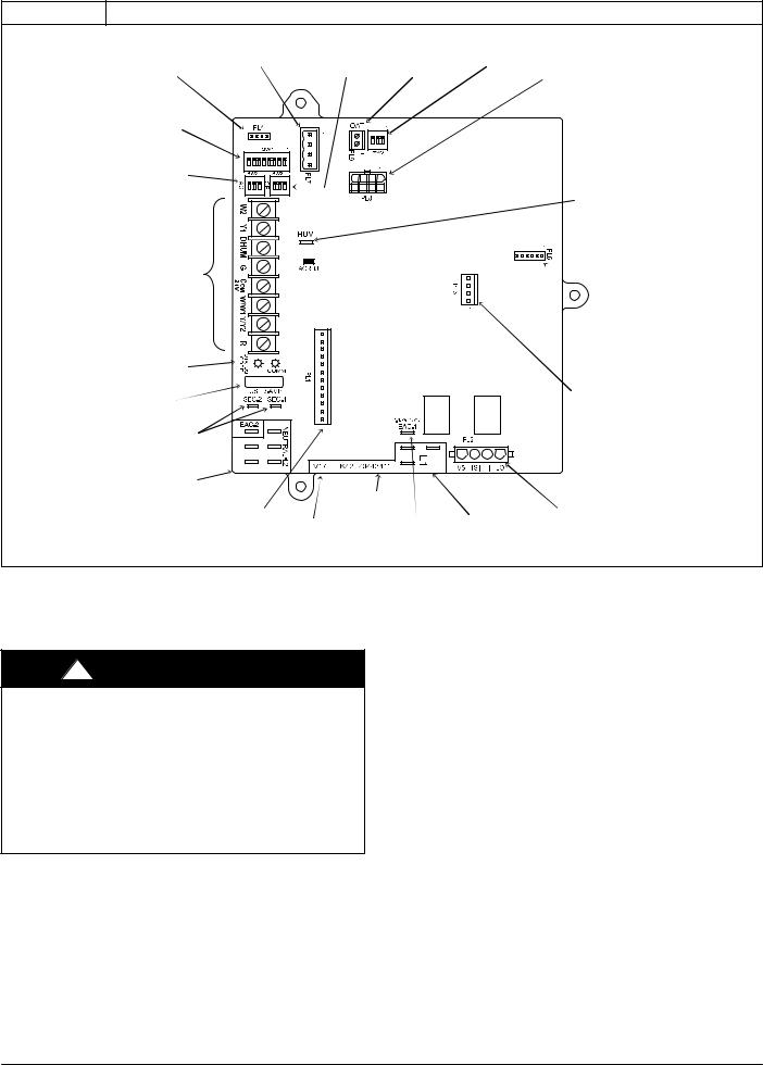
Figure 3 Variable Speed Furnace Control for ECM Blower Motor (Modulating)
COMMUNICATION |
CONTINUOUS FAN |
OUTDOOR |
SW4 SETUP |
|
|
CONNECTOR |
(CF) AIRFLOW |
AIR TEMP |
SWITCHES |
|
|
MODEL PLUG |
SETUP SWITCHES |
CONNECTOR |
|
PL8 ï MODULATING |
|
CONNECTOR |
|
|
|
GAS VALVE |
|
|
|
|
|
CONNECTOR |
|
SW1 SETUP |
|
|
|
|
|
SWITCHES AND |
|
|
|
|
|
BLOWER OFFï |
|
|
|
|
|
DELAY |
|
|
|
|
|
AIR CONDITIONING |
|
|
|
|
|
(A/C) AIRFLOW |
|
|
|
|
|
SETUP SWITCHES |
|
|
|
HUMIDIFIER |
|
|
|
|
|
TERMINAL (24ïVAC |
|
|
|
|
|
0.5 AMP MAX. |
|
24ïV THERMOSTAT |
|
|
|
|
|
TERMINALS |
|
|
|
|
|
|
|
|
|
FLASH |
|
|
|
|
|
UPGRADE |
|
|
|
|
|
CONNECTOR |
|
|
|
|
|
(FACTORY |
|
|
|
|
|
ONLY) |
|
STATUS AND COMM |
|
|
|
|
|
LED LIGHTS |
|
|
|
|
|
3ïAMP FUSE |
|
|
|
PL3 ć ECM BLOWER |
|
|
|
|
HARNESS |
||
|
|
|
|
||
|
|
|
|
CONNECTOR |
|
TRANSFORMER 24ïVAC |
|
|
|
|
|
CONNECTIONS |
|
|
|
|
|
115ïVAC (L2) NEUTRAL |
|
|
|
|
|
CONNECTIONS |
|
|
|
|
|
|
PART NUMBER AND |
|
|
PL2 ć HOT SURFACE |
|
PL1 ć LOW VOLTAGE MAIN |
DATE CODE WWYY |
|
|
||
|
|
IGNITER & INDUCER |
|||
HARNESS CONNECTOR |
|
|
115ïVAC (L1) LINE |
||
EACï1 TERMINAL |
MOTOR CONNECTOR |
||||
|
|||||
SOFTWARE |
(115ïVAC 1.0 AMP MAX.) |
VOLTAGE CONNECTIONS |
|
VERSION |
|||
|
|
L11F091
Adjust Temperature Rise
NOTE: Blower door must be installed when taking temperature rise reading. Leaving blower door off will result in incorrect temperature measurements.
!CAUTION
FURNACE DAMAGE HAZARD
Failure to follow this caution may result in:
SOverheating the heat exchangers or condensing flue gases in heat exchanger areas not designed for condensate
SShortened furnace life
SComponent damage
Temperature rise must be within limits specified on furnace rating plate. Recommended operation is at midpoint of rise range or slightly above.
Furnace must operate within ranges of temperature rise specified on the furnace rating plate. When setup switch SW1-4 is ON, operation will be near the high end of the rise range for improved comfort.
Determine air temperature rise as follows:
1.Place thermometers in return and supply ducts as near furnace as possible. Be sure thermometers do not see heat exchanger so that radiant heat does not affect readings. This practice is particularly important with straight-run ducts.
2.When thermometer readings stabilize, subtract return-air temperature from supply-air temperature to determine air temperature rise.
NOTE: Temperature rise can be determined for Minimum Heat, Intermediate Heat and Maximum Heat operation by locking the furnace in each mode of operation. The mode of operation is based on the position of Set-up switch SW1-2 and SW4-2 on the furnace control board.
The furnace is capable of automatically providing proper airflow to maintain the temperature rise within the range specified on furnace rating plate. If temperature rise is outside this range, proceed as follows:
a.Check gas input for Minimum, Intermediate, and Maximum heat operation.
b.Check derate for altitude if applicable.
c.Check all return and supply ducts for excessive restrictions causing static pressure greater than 0.5-in. w.c.
d.Ensure Min/Int Rise Adjust switch SW1−3 on furnace control is in ON position when a bypass humidifier is used. (See Figure 3 for switch location.)
e.Check Troubleshooting Guide for Variable−Speed Step Modulating Condensing Furnaces.
f.Verify correct model plug is installed.
To lock the furnace in Minimum Heat:
1.Turn SW1−2 ON at the furnace control. Set up switch SW4−2 must be OFF.
2.Connect a jumper across R and W/W1 at the thermostat terminals at the furnace control.
3.Allow the burners to ignite and the blower to turn on.
4.Allow the supply temperature to stabilize and verify the proper rise range.
If the temperature rise is too high or too low in Minimum Heat:
1. Remove jumpers from R and W/W1.
8 |
Specifications subject to change without notice. |
440 04 4700 00 |
|
|
SERVICE AND TECHNICAL SUPPORT MANUAL
2.Wait until the blower off delay is completed.
3.Turn 115 VAC power off.
4.Check the position of Set up switch SW1−3. When set to ON, airflow is raised 18% for Minimum Heat and for Intermediate Heat. Factory default position is OFF.
5.Turn 115 VAC power on.
6.Re−check Minimum Heat Temperature Rise.
To lock the furnace in Intermediate Heat:
1.Turn SW1−2 OFF and SW4−2 ON at the furnace control.
2.Connect a jumper across R and W/W1 at the thermostat terminals at the furnace control.
3.Allow the burners to ignite and the blower to turn on.
4.Allow the supply temperature to stabilize and verify the proper rise range.
If the temperature rise is too high or too low in Intermediate Heat:
1.Remove jumpers from R and W/W1.
2.Wait until the blower off delay is completed.
3.Turn 115 VAC power off.
4.Check the position of Set up switch SW1−3. When set to ON, airflow is raised 18% for Minimum Heat and for Intermediate Heat. Factory default position is OFF.
5.Turn 115 VAC power on.
6.Re−check Intermediate Heat Temperature Rise .
To lock the furnace in Maximum Heat:
1.Connect a jumper across R and W/W1 and W2 at the thermostat terminals at the furnace control.
2.Allow the burners to ignite and the blower to turn on.
3.Allow the supply temperature to stabilize and verify the proper rise range.
If the temperature rise is too high or too low in Maximum Heat:
1.Remove jumpers from R and W/W1 and W2.
2.Wait until the blower off delay is completed.
3.Turn 115 VAC power off.
4.Check the position of Set up switch SW1−4. When set to OFF, and SW1−3 is set to OFF, airflow is raised 10% for Minimum Heat, 7.5% for Intermediate Heat and 17.5% for Maximum Heat. Factory default position is ON. If SW1−3 is ON and SW1−4 is OFF, airflow is raised 18% for Minimum and Intermediate heat and 10% for Maximum Heat.
5.Turn 115 VAC power on.
6.Re−check Maximum Heat Temperature Rise.
After the temperature rise has been verified:
1.Remove jumpers from thermostat terminals.
2.Allow the blower off delay to complete.
3.Turn Set up switches SW1−2 and SW4−2 to the OFF position unless two−stage thermostat operation is desired. (See Figure 4)
4.Proceed to “Adjust Blower Off Delay” or install blower door if complete.
!WARNING
FIRE HAZARD
Failure to follow this warning could result in personal injury, death, and/or property damage.
Reinstall manifold pressure tap plug in gas valve to prevent gas leak.
!CAUTION
FURNACE OVERHEATING HAZARD
Failure to follow this caution may result in reduced furnace life.
Recheck temperature rise. It must be within limits specified on the rating plate. Recommended operation is at the mid−point of rise range or slightly above.
Gas Furnace: (F/G)9MAE
Adjust Blower Off Delay (Heat Mode)
a.Remove blower door if installed.
b.Turn Dip switch SW−7 or SW−8 ON or OFF for desired blower off delay. (See Table 2, Figure 3 and
Figure 4)
Table 2 |
Blower Speed Taps |
|
|
|
|
DESIRED HEATING MODE |
SETUP SWITCH POSITION |
|
BLOWER OFF DELAY |
|
|
(SEC.) |
SW1-7 |
SW1-8 |
90 |
OFF |
OFF |
|
|
|
120 |
ON |
OFF |
|
|
|
150 |
OFF |
ON |
|
|
|
180 |
ON |
ON |
|
|
|
Adjust Cooling Airflow − High−Speed and Low−Speed Cooling
The ECM blower can be adjusted for a range of airflows for low−speed or high−speed cooling. See Table 3 − Airflow Switch Table, Table 6 − Air Delivery − CFM (with Filter) and Figure 4. Furnace Setup Switches and Descriptions. Depending on the model size, the cooling airflow can be adjusted from 1.5 tons to 6 tons of nominal cooling based on 350 CFM ton.
NOTE: 6 ton airflow will truncate at 2200 CFM on applicable models.
The high−speed or single−speed cooling airflow is adjusted by turning setup switches SW2−1, SW2−2 and SW2−3 either ON or OFF. Select the required airflow from Table 6. Table 6 is based on 350 CFM per ton. For other CFM per ton setup switch selections, see Table 3, Figure 4 and Figure 15.
The Continuous Fan airflow selection via setup switches SW3 is also the airflow for low−speed cooling when the furnace is used with a two−speed cooling or heat pump unit. Adjust the Continuous Fan CFM setup switches SW3 to match the airflow required for low−speed cooling. Select the required airflow from
Table 6 and Figure 4.
NOTE: The airflow selected via SW3 (low−speed cooling airflow) cannot exceed the airflow selected via SW2 (high−speed cooling airflow). For other CFM per ton setup switch selections, see Table 3 and Figure 4.
NOTE: The airflow settings for SW2 and SW3 selections are the same, EXCEPT for the default values. (See Table 6)
For a complete explanation of cooling airflow, refer to the section titled “Sequence of Operation.”
Adjust Continuous Fan Airflow/Low Speed Cooling Airflow
NOTE: When the furnace is used with a two−speed cooling or heat pump unit, the airflow selected for Continuous Fan via setup switch SW3 will also be the airflow used for low−speed cooling, and vice versa.
NOTE: When the furnace is used with a two−speed cooling or heat pump unit, adjust the Continuous Fan CFM setup switches SW3 to match the airflow required for low−speed cooling.
Select the required Continuous Fan airflow using setup switches SW3 as shown in Table 3, Figure 4 and Figure 15.
440 04 4700 00 |
Specifications subject to change without notice. |
9 |
|
|
SERVICE AND TECHNICAL SUPPORT MANUAL |
Gas Furnace: (F/G)9MAE |
|
|
Figure 4
1 |
|
|
|
O N |
|
SW2 |
|
|
|
|
1 |
|
|
|
|
|
|
|
|
|
|
3 2 |
|
|
|
|
|
||
|
|
|
|
||
|
|
|
|
|
|
AC
1 |
|
|
|
O N |
|
SW3 |
|
|
|
|
2 1 |
|
|
|
|
||
|
|
|
|
||
|
|
|
|
3 |
|
|
|
|
|
|
|
|
|
|
|
|
|
CF
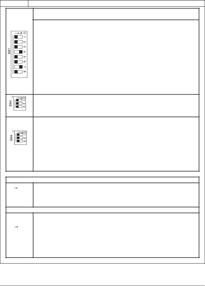
Furnace Setup Switch Description
Furnace Setup Switch Description
|
SETUP SWITCH |
SWITCH NAME |
NORMAL POSITION |
DESCRIPTION OF USE |
|
|
|
|
Turn ON to retrieve up to 7 stored status codes for |
|
SW1-1 |
Status Code Recovery |
OFF |
troubleshooting assistance when R thermostat lead is |
|
|
|
|
disconnected. |
|
|
Minimum Heat Only |
|
When SW1-2 and SW4-2 are OFF allows Modulating operation |
|
|
|
with a single stage thermostat. Turn ON SW1-2 when using |
|
|
SW1-2 |
(Adaptive Heat Mode |
OFF |
two-stage thermostat to allow Minimum Heat operation when |
|
when SW1-2 and SW4-2 |
R to W/W1 closed and a Maximum heat operation when R to |
||
|
|
|
||
|
|
are OFF) |
|
W/W1 and R to W2 close. |
|
|
|
|
|
|
|
|
|
Turn ON to increase Minimum Heat and Intermediate Heat |
|
SW1-3 |
Min/Int Heat Rise |
OFF |
airflow by 18 percent. This compensates for increased return |
|
Adjustment |
air temperature caused with bypass humidifier. This also |
||
|
|
|
||
|
|
|
|
increases the Intermediate Heat inducer speed 15 percent. |
|
|
Comfort/Efficiency |
|
Turn ON to decrease Minimum heat airflow by 10 percent, |
|
SW1-4 |
ON |
Intermediate Heat airflow 7.5 percent and Maximum Heat |
|
|
Adjustment |
|||
|
|
|
airflow 17.5 percent for maximum comfort. |
|
|
|
|
|
|
|
SW1-5 |
CFM per ton adjust |
OFF |
Turn ON for 400 CFM per ton, Turn OFF for 350 CFM per ton. |
|
See also SW4. |
|||
|
|
|
|
|
|
|
|
|
|
|
|
|
|
Turn ON to initiate Component Self Test for troubleshooting |
|
SW1-6 |
Component Self Test |
OFF |
assistance when R thermostat lead is disconnected. Turn |
|
|
|
|
OFF when Self Test is completed. |
|
|
|
|
Blower Off Delay time – adjustable 90 seconds to 180 |
|
SW1-7 & SW1-8 |
Blower OFF delay |
ON or OFF |
seconds. See table in Adjustments section or refer to unit |
|
|
|
|
wiring diagram. |
|
|
|
|
When SW1-2 and SW4-2 are OFF allows Modulating operation |
|
|
Intermediate Heat |
|
with a single stage thermostat. Turn ON SW4-2 when using |
|
|
Only |
|
two-stage thermostat to allow Intermediate Heat operation |
|
SW4-2 |
(Adaptive Heat Mode |
OFF |
when R to W/W1 closed and a Maximum heat operation when |
|
|
when both SW1-2 and |
|
R to W/W1 and R to W2 close. |
|
|
|
|
|
|
|
SW4-2 are OFF) |
|
|
|
|
|
|
Allows additional CFM per ton selections when used with SW |
|
|
|
|
1-5 |
|
|
|
|
325 CFM per ton (nominal) when SW 4-3 ON and SW 1-5 OFF |
|
|
|
|
350 CFM per ton (nominal) when SW 4-3 OFF and SW 1-5 OFF |
|
SW4-3 |
CFM per ton Adjust |
OFF |
370 CFM per ton (nominal) when SW4-3 ON and SW 1-5 ON |
|
|
|
|
|
|
|
|
|
400 CFM per ton (nominal) when SW 1-5 ON and SW 4-3 OFF |
|
|
|
|
See Air Delivery Tables for model specific CFM vs. static |
|
|
|
|
pressure |
|
|
|
|
|
AIR CONDITIONING (A/C) SETUP SWITCHES
SW 2, AC (Cooling Airflow) SETUP SWITCHES
The AC setup switch selects desired cooling or high stage cooling (two stage units) airflow.
See Cooling Air Delivery Tables for specific switch settings
CONTINUOUS FAN (CF) SETUP SWITCHES
SW 3, CF (Continuous Fan) SETUP SWITCHES
The CF setup switch selects desired Continuous Fan Airflow
The CF switch position is the Low Cooling airflow selection for two stage cooling units.
SW 3 cannot be set for airflow higher than SW 2
See Continuous Fan Air Delivery Tables for specific switch settings
A11575
10 |
Specifications subject to change without notice. |
440 04 4700 00 |
|
|

SERVICE AND TECHNICAL SUPPORT MANUAL |
Gas Furnace: (F/G)9MAE |
|
|
Table 3 |
Airflow Switch Table |
|
|
|
|
|
|
||
|
NOMINAL AIRFLOW BASED ON 350 CFM/TON (Factory Default - SW1-5 = OFF, SW4-3 = OFF) |
|
|
||||||
|
SW2 Clg Default |
SW3 CF Default |
COOLING (SW2) AND CONTINUOUS FAN (SW3) AIRFLOW: SET-UP SWITCH POSITIONS |
||||||
Model Size |
|
|
|
|
|
|
|
|
|
|
O |
O |
O |
O |
O |
O |
O |
O |
O |
|
3 2 1 N |
3 2 1 N |
3 2 1 N |
3 2 1 N |
3 2 1 N |
3 2 1 N |
3 2 1 N |
3 2 1 N |
3 2 1 N |
060-14 |
1050 |
525 |
525 |
700 |
875 |
1050 |
1225 |
1225 |
1225 |
080-14 |
1050 |
525 |
525 |
700 |
875 |
1050 |
1225 |
1225 |
1225 |
060-20 |
1750 |
700 |
700 |
875 |
1050 |
1225 |
1400 |
1750 |
1750 |
080-20 |
1750 |
700 |
700 |
875 |
1050 |
1225 |
1400 |
1750 |
1750 |
100-22 |
1750 |
700 |
700 |
875 |
1050 |
1225 |
1400 |
1750 |
2100 |
120-22 |
1750 |
875 |
700 |
875 |
1050 |
1225 |
1400 |
1750 |
2100 |
|
|
NOMINAL AIRFLOW BASED ON 400 CFM/TON (SW1-5 = ON, SW4-3 = OFF) |
|
|
|||||
|
SW2 Clg Default |
SW3 CF Default |
COOLING (SW2) AND CONTINUOUS FAN (SW3) AIRFLOW: SET-UP SWITCH POSITIONS |
||||||
Model Size |
|
|
|
|
|
|
|
|
|
|
O |
O |
O |
O |
O |
O |
O |
O |
O |
|
3 2 1 N |
3 2 1 N |
3 2 1 N |
3 2 1 N |
3 2 1 N |
3 2 1 N |
3 2 1 N |
3 2 1 N |
3 2 1 N |
060-14 |
1200 |
600 |
600 |
800 |
1000 |
1200 |
1400 |
1400 |
1400 |
080-14 |
1200 |
600 |
600 |
800 |
1000 |
1200 |
1400 |
1400 |
1400 |
060-20 |
2000 |
800 |
800 |
1000 |
1200 |
1400 |
1600 |
2000 |
2000 |
080-20 |
2000 |
800 |
800 |
1000 |
1200 |
1400 |
1600 |
2000 |
2000 |
100-22 |
2000 |
800 |
800 |
1000 |
1200 |
1400 |
1600 |
2000 |
2100 |
120-22 |
2000 |
1000 |
800 |
1000 |
1200 |
1400 |
1600 |
2000 |
2100 |
|
|
NOMINAL AIRFLOW BASED ON 325 CFM/TON (SW1-5 = OFF, SW4-3 = ON) |
|
|
|||||
|
SW2 Clg Default |
SW3 CF Default |
COOLING (SW2) AND CONTINUOUS FAN (SW3) AIRFLOW: SET-UP SWITCH POSITIONS |
||||||
Model Size |
|
|
|
|
|
|
|
|
|
|
O |
O |
O |
O |
O |
O |
O |
O |
O |
|
3 2 1 N |
3 2 1 N |
3 2 1 N |
3 2 1 N |
3 2 1 N |
3 2 1 N |
3 2 1 N |
3 2 1 N |
3 2 1 N |
060-14 |
976 |
488 |
488 |
651 |
814 |
976 |
1139 |
1139 |
1139 |
080-14 |
976 |
488 |
488 |
651 |
814 |
976 |
1139 |
1139 |
1139 |
060-20 |
1627 |
651 |
651 |
814 |
976 |
1139 |
1302 |
1627 |
1627 |
080-20 |
1627 |
651 |
651 |
814 |
976 |
1139 |
1302 |
1627 |
1627 |
100-22 |
1627 |
651 |
651 |
814 |
976 |
1139 |
1302 |
1627 |
1953 |
120-22 |
1627 |
814 |
651 |
814 |
976 |
1139 |
1302 |
1627 |
1953 |
|
|
NOMINAL AIRFLOW BASED ON 370 CFM/TON (SW1-5 = ON, SW4-3 = ON) |
|
|
|||||
|
SW2 Clg Default |
SW3 CF Default |
COOLING (SW2) AND CONTINUOUS FAN (SW3) AIRFLOW: SET-UP SWITCH POSITIONS |
||||||
Model Size |
|
|
|
|
|
|
|
|
|
|
O |
O |
O |
O |
O |
O |
O |
O |
O |
|
3 2 1 N |
3 2 1 N |
3 2 1 N |
3 2 1 N |
3 2 1 N |
3 2 1 N |
3 2 1 N |
3 2 1 N |
3 2 1 N |
060-14 |
1116 |
558 |
558 |
744 |
930 |
1116 |
1302 |
1302 |
1302 |
080-14 |
1116 |
558 |
558 |
744 |
930 |
1116 |
1302 |
1302 |
1302 |
060-20 |
1860 |
744 |
744 |
930 |
1116 |
1302 |
1488 |
1860 |
1860 |
080-20 |
1860 |
744 |
744 |
930 |
1116 |
1302 |
1488 |
1860 |
1860 |
100-22 |
1860 |
744 |
744 |
930 |
1116 |
1302 |
1488 |
1860 |
2100 |
120-22 |
1860 |
930 |
744 |
930 |
1116 |
1302 |
1488 |
1860 |
2100 |
|
|
|
|
|
|
|
|
|
L11F092 |
Adjust Thermostat Heat Anticipator
a.Mechanical thermostat. Set thermostat heat anticipator to match the amp. draw of the electrical components in the R−W/W1 circuit. Accurate amp. draw readings can be obtained at the wires normally connected to thermostat subbase terminals, R and W. The thermostat anticipator should NOT be in the circuit while measuring current.
(1.) Set SW1−2 switch on furnace control board to ON.
(2.) Remove thermostat from subbase or from wall.
(3.) Connect an amp. meter as shown in Figure 5 across the R and W subbase terminals or R and W wires at wall.
(4.) Record amp. draw across terminals when furnace is in minimum heat and after blower starts.
(5.) Set heat anticipator on thermostat per thermostat instructions and install on subbase or wall.
(6.) Turn SW1−2 switch OFF.
(7.) Install blower door.
b.Electronic thermostat: Set cycle rate for three cycles per hr.
440 04 4700 00 |
Specifications subject to change without notice. |
11 |
|
|

SERVICE AND TECHNICAL SUPPORT MANUAL
Figure 5 Amp. Draw Check with Ammeter
THERMOSTAT SUBBASE TERMINALS WITH THERMOSTAT REMOVED (ANITICIPATOR, CLOCK, ETC., MUST BE OUT OF CIRCUIT.)
HOOK-AROUND AMMETER
R Y W G
10 TURNS
 FROM UNIT 24-V
CONTROL TERMINALS
EXAMPLE: |
5.0 AMPS ON AMMETER |
= |
0.5 AMPS FOR THERMOSTAT |
|
10 TURNS AROUND JAWS |
ANTICIPATOR SETTING |
|||
|
|
|||
|
|
|
A96316 |
Check Safety Controls
The flame sensor, gas valve, and pressure switch were all checked in the Start−up procedure section as part of normal operation.
1.Check Main Limit Switch
This control shuts off combustion system and energizes air−circulating blower motor, if furnace overheats. By using this method to check limit control, it can be established that limit is functioning properly and will operate if there is a restricted return−air supply or motor failure. If limit control does not function during this test, cause must be determined and corrected.
a. Run furnace for at least five minutes.
Gas Furnace: (F/G)9MAE
b.Gradually block off return air with a piece of cardboard or sheet metal until the limit trips.
c.Unblock return air to permit normal circulation.
d.Burners will re−light when furnace cools down.
2.Check Pressure Switch(es)
This control proves operation of the draft inducer blower.
a.Turn off 115−v power to furnace.
b.Disconnect inducer motor lead wires from wire harness.
c.Turn on 115−v power to furnace.
d.Set thermostat to “call for heat” and wait 1 minute. When pressure switch is functioning properly, hot surface igniter should NOT glow and control diagnostic light flashes a status code 3. If hot surface igniter glows when inducer motor is disconnected, shut down furnace immediately.
e.Determine reason pressure switch did not function properly and correct condition.
f.Turn off 115−v power to furnace.
g.Reconnect inducer motor wires, replace blower door, and turn on 115−v power.
h.Blower will run for 90 seconds before beginning the call for heat again.
i.Furnace should ignite normally.
Checklist
1.Put away tools and instruments. Clean up debris.
2.Verify that switches SW1−1 and SW1−6 are OFF and other setup switches are set as desired. Verify that switches SW1−7 and SW1−8 for the blower OFF DELAY are set as desired per Table 2.
3.Verify that blower and control doors are properly installed.
4.Cycle test furnace with room thermostat.
5.Check operation of accessories per manufacturer’s instructions.
6.Review Home Owner’s Information with owner.
7.Attach literature packet to furnace.
12 |
Specifications subject to change without notice. |
440 04 4700 00 |
|
|
 Loading...